Table of Contents
Advertisement
Quick Links
FOR CAR USE ONLY
TOPVIEW
ALPINE ELECTRONICS MARKETING, INC.
1-1-8 Nishi Gotanda,
Shinagawa-ku,
Tokyo 141-0031, Japan
Phone 03-5496-8231
ALPINE ELECTRONICS OF AMERICA, INC.
19145 Gramercy Place, Torrance,
California 90501, U.S.A.
Phone 1-800-ALPINE-1 (1-800-257-4631)
ALPINE ELECTRONICS OF CANADA, INC.
777 Supertest Road, Toronto,
Ontario M3J 2M9, Canada
Phone 1-800-ALPINE-1 (1-800-257-4631)
YAMAGATA Co., Ltd.
2-6-34, Takashima, Nishi-ku, Yokohama-shi,
Kanagawa, 220-8515 Japan
CAMERA SYSTEM
®
HCE-C500
•
OWNER'S MANUAL
Please read before using this equipment.
ALPINE ELECTRONICS OF AUSTRALIA PTY. LTD.
161-165 Princes Highway, Hallam
Victoria 3803, Australia
Phone 03-8787-1200
ALPINE ELECTRONICS GmbH
Wilhelm-Wagenfeld-Str. 1-3,
80807 München, Germany
Phone 089-32 42 640
ALPINE ELECTRONICS OF U.K. LTD.
Alpine House
Fletchamstead Highway,
Coventry CV4 9TW, U.K.
Phone 0870-33 33 763
ALPINE ELECTRONICS FRANCE S.A.R.L.
(RCS PONTOISE B 338 101 280)
98, Rue de la Belle Etoile, Z.I. Paris Nord Il,
B.P. 50016, 95945 Roissy Charles de Gaulle
Cedex, France
Phone 01-48638989
ALPINE ITALIA S.p.A.
Viale C. Colombo 8, 20090 Trezzano
Sul Naviglio (MI), Italy
Phone 02-484781
ALPINE ELECTRONICS DE ESPAÑA, S.A.
Portal de Gamarra 36, Pabellón, 32
01013 Vitoria (Alava)-APDO 133, Spain
Phone 945-283588
ALPINE ELECTRONICS (BENELUX) GmbH
Leuvensesteenweg 510-B6,
1930 Zaventem, Belgium
Phone 02-725-13 15
Designed by ALPINE Japan
Printed in Japan (Y_A5)
68-18693Z84-A
EN
Advertisement
Table of Contents

Subscribe to Our Youtube Channel
Related Manuals for Alpine TOPVIEW HCE-C500


Summary of Contents for Alpine TOPVIEW HCE-C500
-
Page 1: Camera System
® HCE-C500 • OWNER’S MANUAL Please read before using this equipment. ALPINE ELECTRONICS MARKETING, INC. ALPINE ELECTRONICS OF AUSTRALIA PTY. LTD. ALPINE ITALIA S.p.A. 161-165 Princes Highway, Hallam 1-1-8 Nishi Gotanda, Viale C. Colombo 8, 20090 Trezzano Victoria 3803, Australia... -
Page 3: Table Of Contents
ENGLISH Contents Installation and Connections Check Accessory Parts ....17 Operating Instructions Connections ........18 System Example ......19 WARNING Information WARNING ........2 Specifications ........20 CAUTION ......... 3 In Case of Difficulty .......20 NOTICE ..........3 Feature About the TOPVIEW® CAMERA SYSTEM ..........4 Example of Camera Installation .... -
Page 4: Operating Instructions
USE THE CORRECT AMPERE RATING WHEN REPLACING or damage to the unit and/or the vehicle. When in doubt, FUSES. consult your Alpine dealer. Failure to do so may result in fire or electric shock. USE THIS PRODUCT FOR MOBILE 12 VOLT USE ONLY IN CARS WITH A 12 VOLT NEGATIVE GROUND. -
Page 5: Caution
HALT USE IMMEDIATELY IF A PROBLEM APPEARS. Failure to do so may cause personal injury or damage to the product. Return it to your authorized Alpine dealer or the nearest Alpine Service Center for repairing. EXCEPT FOR THE CAMERA, DO NOT ATTACH ANY PARTS TO AREAS WHICH WILL GET WET, OR WHERE THERE IS A LOT OF HUMIDITY OR DUST. -
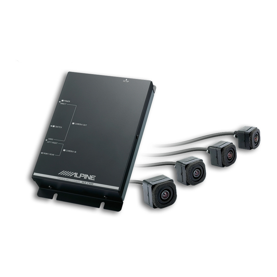
Page 6: Feature
Feature About the TOPVIEW® CAMERA SYSTEM The TOPVIEW® CAMERA SYSTEM displays the blind area outside the driver’s range of vision, using four cameras installed on the front, back, right and left of the vehicle. It is useful for checking for objects around the vehicle. - Page 7 Rear View Display Indications <Rear Panorama View> <Rear Mirror View> <Rear Top View> <Rear View> • With this system, the brightness and tint of each camera is automatically adjusted. When driving in areas where the brightness or tint varies widely, the brightness or tint of the camera image on the screen may become unstable. •...
-
Page 8: Camera Image
Only displayed in the Varies with image pattern rear view image. *1 If no caution message is displayed, be sure to make the correct display settings. Have an authorized Alpine dealer perform the correct display settings in calibration mode. A: Current image range B: Current image pattern <Front View Image>... -
Page 9: About The Front Camera Image And Camera Guide
About the Front Camera Image and Front Top View Camera Guide The split-screen image displays an all-round view from above the vehicle and the front view. Use this when you want to check for objects Front Panorama View around or in front of the vehicle. For example, Displays a wider-angled perspective of the area in when parking the vehicle in a garage. -
Page 10: About The Rear Camera Image And Camera Guide
• With Top View, the camera image around the joins Rear Mirror View or borders may not be displayed. For details, refer to The triple-screen image displays the area on each “About Top View Blind Spots” (page 13). side behind the vehicle. •... -
Page 11: Rear View
Indication mark meaning Rear View C Guidelines representing a distance of Displays the area behind the vehicle. approx. 0.5 m all round the vehicle. Use this when reversing into a garage or when checking for objects behind the vehicle. • Rear View: Refer to “Rear View”... -
Page 12: Error Between The Display And Actual Road Surface
Distance guidelines Error Between the Display and Actual Road Surface The distance guides represent the ground level distance from the rear bumper. It is difficult to Under the following conditions, errors are accurately estimate the distance to objects above produced between the display guidelines and the ground level. - Page 13 When there is a steep downward slope behind the car (example) <Screen> <Situation of the car> Error Error In the case of a downward slope behind the car, the distance guides are displayed farther from the rear bumper than the actual distance.
-
Page 14: About Calibration
Before using this camera system, calibration is required to set the vehicle width and guidelines for the specific vehicle model. A special measuring kit is needed and the system can only be calibrated by an authorised ALPINE dealer. For details, contact your ALPINE dealer. - Page 15 With Top View, a blind zone exists where the camera images meet. The calibration settings will have been configured by your ALPINE dealer to minimise this blind zone, but if you change the height of the vehicle after purchasing the camera system (after the system has been calibrated), the following changes to the blind zone may occur.
-
Page 16: Camera Operation
Camera Operation Displaying the Camera Image This camera system enables you to perform the Displaying the Camera Image by following operations in the camera view, using the Pressing the PDC button iDrive Controller. Availability of this function depends on the iDrive Controller Operation factory configuration of the vehicle. -
Page 17: Displaying The Camera Image Using The Idrive Controller
Displaying the Camera Image using Displaying the rear view image the iDrive Controller while the car is in reverse Displaying the rear image by shifting the gear iDrive Controller lever. Shift the gear lever to the reverse (R) position. The rear view image is displayed while the car remains in reverse. -
Page 18: Switching Image Patterns
Switching Image Patterns The image pattern switches with operation (B) of the iDrive Controller. For details of the image patterns, refer to “Camera Image” (page 6). <Front view> Front Panorama View Front Side View Front Top View Front Corner View <Rear view>... -
Page 19: Installation And Connections
Do not tap into these leads to provide power Side camera (L) x1 for this unit. When connecting the HCE-C500 series to the Side camera (R) x1 fuse box, make sure the fuse for the intended circuit of the... -
Page 20: Connections
(Orange/White) Reverse Input Lead REVERSE SETUP switch (ON/OFF) This switch is used by your ALPINE dealer when calibrating this system. It is normally set to “OFF”. If you accidentally set it to “ON”, the system may need to be recalibrated. -
Page 21: System Example
System Example <Monitor> Battery Battery lead (Yellow) (12V) BATT Fuse (7.5A) <I/F Box> Ground lead (Black) Switched power lead Switched power lead (Ignition) (Red) (Red) Reverse lead Reverse lead REVERSE (White) (Orange/White) Switch Connector Currently not used. Camera input RCA extension cable Video output connector (Yellow) adapter Rear camera output... -
Page 22: Information
Information In Case of Difficulty • The camera image does not appear. (Images Specifications other than that of the camera are normal.) Cause Solution Camera section The ignition key is Set the ignition key to ON. set to a position other Image sensor . - Page 23 If there is a serious symptom, for example, the distance guidance marks deviates significantly from the actual distance, stop using this system and contact your ALPINE dealer.
Need help?
Do you have a question about the TOPVIEW HCE-C500 and is the answer not in the manual?
Questions and answers