Table of Contents
Advertisement
Quick Links
Advertisement
Table of Contents

Related Manuals for LeCroy MS-500


Summary of Contents for LeCroy MS-500
- Page 1 ’ ’...
- Page 2 © 2009 by LeCroy Corporation. All rights reserved. LeCroy, ActiveDSO, WaveLink, JitterTrack, WavePro, WaveMaster, WaveSurfer, WaveExpert, and Waverunner are registered trademarks of LeCroy Corporation. Other product or brand names are trademarks or requested trademarks of their respective holders. Information in this publication supersedes all earlier versions.
-
Page 3: Table Of Contents
Connecting the MS-500 System to the Oscilloscope ..............13 Verifying Proper MS-500 Connection to your Oscilloscope and the Device Under Test ....16 If you are concerned that your digital signals aren’t being displayed correctly, it is a good idea to check by viewing the digital signals one at a time with an analog channel. - Page 4 MS-500 Mixed Signal Oscilloscope Option Digital Logic Setup ........................26 DIGITAL TRIGGER SETUP ................28 Overview ............................28 Creating a Pattern Trigger ......................28 Logic Pattern Trigger Setup ......................29 Logic Bus Trigger Setup ......................... 30 Digital Logic Threshold Setup ......................30 CHARACTERIZE DIGITAL OR MIXED SIGNAL SYSTEM PERFORMANCE ...
-
Page 5: Safety Requirements
Altitude: Up to 2,000 m CAUTION To avoid personal injury or damage to the MS-500 or any equipment connected to it, review and comply with the following safety precautions. Use only as intended. Use of the MS-500 and/or the equipment it is connected to in a manner other than specified may impair the protection mechanisms. -
Page 6: Introduction
The MS-500 and MS-500-36 are identical except the MS-500-36 standard configuration is for 36 channels. The MS-500-36 can be operated in 36 or 18 channel mode for higher performance. The MS-500 is configured as an 18 channel instrument and can be upgraded with an additional lead set to support 36 channels. -
Page 7: Returning A Product For Service Or Repair
Returning a Product for Service or Repair If you suspect that you have a problem with the MS-500 you should first contact your local LeCroy service center so they can ascertain whether the component is defective. If you need to return a LeCroy product, provide model identification by providing the model name and serial number, describe the defect or failure, and give us your name and telephone number. -
Page 8: Standard And Accessory Equipment
36 channel digital acquisition and triggering. Qty. 1 16” (40.64 cm) Digital Lead Set – Interfaces the MS-500 to the device under test. The lead set terminates in a 25 mil pin socket. Micro-gripper probes of various ... -
Page 9: The Ms-500 Software
Qty. 1 Quick Reference Guide Qty. 1 Operator’s Manual The MS-500 Software The standard MS-500 software adds the following capability to the LeCroy oscilloscope software dialogs: Analog, Digital and Combination Trigger Modes – Allows you to choose whether to set an analog trigger condition, a digital trigger condition or a pattern consisting of analog and digital signals. -
Page 10: Accessories
Digital Threshold Setup – Provides the means to define a logic threshold for digital trace calculation. The MS-500 Hardware and Software requires no traceable calibration or adjustment. However, the oscilloscope used with the MS-500 does require periodic calibration and adjustment. - Page 11 Includes 10 probes with color-coded leads. MSO-MICTOR – Mictor Connection cable, 16” (40.64 cm), 36 channel connector. MSO-3M - Interconnect cable, 16” (40.64 cm) mates with 3M connectors, 2520-6002 and 25205002. MS-500-OM-E Rev C ISSUED: June, 2009...
-
Page 12: Description Of Operation
MS-500 will not operate. However, the MS-500 can support a signal as low as 100 mV only if the input signal’s quality is adequate. The MS-500 keeps sampling its inputs until the oscilloscope is put into STOP trigger mode. Data is stored in a 50 Mpt internal memory that is periodically transferred to the oscilloscope via the USB2.0 cable. -
Page 13: Getting Started With The Ms-500
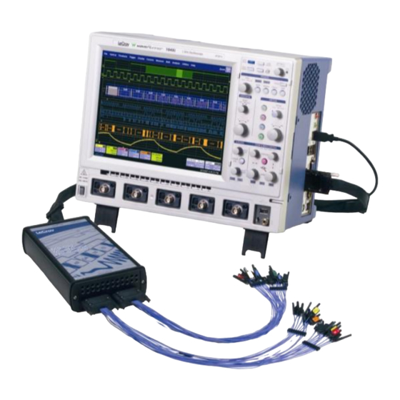
GETTING STARTED WITH THE MS-500 Overview The MS-500 is a complete system that interfaces with the oscilloscope in a number of ways that make it easier to do the following: Set analog, digital and combination triggers. View all analog and digital signal information on the oscilloscope grid, with all signals time-correlated All setup is done in the user-friendly oscilloscope dialogs –... - Page 14 MS-500 Mixed Signal Oscilloscope Option 2. Connect the USB 2.0 cable (attached to the LeCroy Bus cable) to any of the side mounted USB ports on the oscilloscope. 3. Connect the other end of the LeCroy Bus cable to the MS-500 and fasten the thumb screws.
- Page 15 4. Connect the other end of the USB2.0 Cable to the MS-500. 5. Connect the Digital Lead Set to the other end of the MS-500 (labeled Digital Inputs, D0 – D17) and fasten the thumb screws. For MS-500-36 repeat this process with the lead set labeled D18 –...
-
Page 16: Verifying Proper Ms-500 Connection To Your Oscilloscope And The Device Under Test
MS-500 Mixed Signal Oscilloscope Option Verifying Proper MS-500 Connection to your Oscilloscope and the Device Under Test If you are concerned that your digital signals aren’t being displayed correctly, it is a good idea to check by viewing the digital signals one at a time with an analog channel. This can point out errors in your connection or in your logic threshold setup. -
Page 17: Channel Groupings
The standard terminations on the digital lead sets can be pushed directly onto 25-mil pins. MicroGrippers or NanoGrippers may also be used to probe the test circuit’s pins. LeCroy provides a selection of small, medium, and large grippers for various pitch sizes. A more complete selection of adapter probes is available for most chips from Emulation Technology Inc., Yamaichi... - Page 18 MS-500 Mixed Signal Oscilloscope Option Input voltages less than the threshold are converted to 0. Input voltages greater than the threshold are converted to 1. Threshold level Input signal Sample points Digitized waveform The threshold levels can be set between –10.0 V and +10.0 V. TTL circuits use a threshold voltage level of 1.58 V.
-
Page 19: Minimum Voltage Swing
MS-500 will not operate. However, the MS-500 can support a signal as low as 100 mV only if the input signal’s quality is adequate. Threshold from + 50 mV to + 1.4 V Threshold from - 50 mV to - 1.4 V... -
Page 20: Accessing The Ms-500 Oscilloscope Mixed Signal Option Toolset
ACCESSING THE MS-500 OSCILLOSCOPE MIXED SIGNAL OPTION TOOLSET Overview MS-500 trigger and digital line display tools are easily accessible in a variety of ways. The MS- 500 option adds additional dialogs (menus) to the existing oscilloscope. These dialogs are defined as: ... -
Page 21: Digital Trace Groups
Digital dialogs. Logic Setup is where you can set the crossing threshold for determining whether the logic level is a 1 or a 0. Other ways to access the MS-500 Trigger dialogs include: 1. Touching the Trigger trace descriptor label. - Page 22 MS-500 Mixed Signal Oscilloscope Option You can access these dialogs at any other time by using the following steps: 1. Touch Vertical on the menu bar, and select one of the four Digital traces. This turns the Digital trace ON and opens the corresponding dialog box.
-
Page 23: Digital Trace Group Setup
Line name by trace trace group by mouse, or just buttons to touching this group ON checking this use them as a scroll or OFF, summary view through all just like a 36 digital Channel lines MS-500-OM-E Rev C ISSUED: June, 2009... - Page 24 MS-500 Mixed Signal Oscilloscope Option Additional capability is described in the following table: Provides a method to quickly turn all digital lines in the Digital trace group OFF or ON. The default is for all digital lines to be ON. As lines are turned OFF, they automatically resize to take up more of the grid and be easier to see.
-
Page 25: Digital Logic Threshold Setup
Digital Setup or Digital Trigger Setup menus (it is the same setup, but is in two different places for operator convenience). Input voltages less than the threshold are converted to 0. Input voltages greater than the threshold are converted to 1. Threshold level Input signal Sample points Digitized waveform MS-500-OM-E Rev C ISSUED: June, 2009... -
Page 26: Digital Logic Setup
MS-500 will not operate. However, the MS-500 can support a signal as low as 100 mV only if the input signal’s quality is adequate. Threshold from + 50 mV to + 1.4 V Threshold from - 50 mV to - 1.4 V... - Page 27 Touch inside the Logic Family selection to view a selection list. If you select User Defined, then you are able to define the voltage level. Otherwise, the Voltage Level selection is grayed out. MS-500-OM-E Rev C ISSUED: June, 2009...
-
Page 28: Digital Trigger Setup
While the MS-500 Mixed Signal Oscilloscope option has a very powerful and flexible Digital trigger, it is also very easy to set up basic triggering. Connecting the MS-500 to your circuit is described in the preceding chapters and is a digital triggering requirement. -
Page 29: Logic Pattern Trigger Setup
You may set a digital line to any value in the Logic trigger setup even if it is not defined as part of a Digital group. You can set multiple digital lines to different edge conditions. However, the edge conditions are always grouped in an OR trigger condition. MS-500-OM-E Rev C ISSUED: June, 2009... -
Page 30: Logic Bus Trigger Setup
MS-500 Mixed Signal Oscilloscope Option Logic Bus Trigger Setup The Logic Bus Trigger setup dialog is shown as follows: The Logic Bus trigger dialog is very similar to the Digital Logic trigger dialog. The main difference is that you must select a Digital source (Digital1, Digital2, Digital3, or Digital4). In addition, only those bits that are defined as part of that Digital group can be defined in the Logic Bus setup dialog. - Page 31 You can select various Logic Families, or select User Defined and define a custom threshold crossing. Touch inside the Logic Family selection to view a selection list. If you select User Defined, voltage level can be defined. Otherwise, the Voltage Level selection is grayed out. MS-500-OM-E Rev C ISSUED: June, 2009...
-
Page 32: Characterize Digital Or Mixed Signal System Performance
MS-500 Mixed Signal Oscilloscope Option CHARACTERIZE DIGITAL OR MIXED SIGNAL SYSTEM PERFORMANCE Overview The oscilloscope contains a number of built-in tools, such as cursors, measurement parameters, statistics, and optional graphical analysis tools that allow you to characterize your DUT’s performance. The number and type of these tools change depending on whether you are using a WaveRunner or a WaveSurfer oscilloscope and what other software options are loaded on your instrument. -
Page 33: Using Measurement Parameters
Select gating from the Measure dialog by selecting the tab for the appropriate measurement (P1, P2, etc.) and then setting the start and stop for the gate. Reference the oscilloscope’s On-Line Help for more information on how to set gating. MS-500-OM-E Rev C ISSUED: June, 2009... -
Page 34: Using Statistics And Graphing
Simply touch the appropriate box to checkmark it and turn it ON; or touch it again to turn it OFF. In addition, some optional LeCroy programs (WaveRunner Xi only) add capability to produce larger histograms and trends of your measurement parameters. -
Page 35: Isolate And Analyze Signal Activity
25 Mpts on 2 channels. WaveSurfer Xs oscilloscopes can capture up to 10 Mpts on 4 channels The MS-500 option adds 900 Mpts of digital memory (50 Mpts/ch on 18 channels, 25 Mpts/ch on 36 channels). If you wish, all this memory can be 100% pre-trigger, 100% post-trigger, or something in between. -
Page 36: Zooming On Your Waveforms
MS-500 Mixed Signal Oscilloscope Option Zooming on Your Waveforms There are a number of ways to zoom a mix of analog and digital signals. The easiest method is to STOP the acquisition and then simply adjust the timebase Time/Div and Delay knobs on the front panel. - Page 37 (WaveSurfer Xs Series) to adjust the vertical and horizontal scale and position. Reference your oscilloscope operator’s manual for more information. Reference your oscilloscope’s On-Line Help or Getting Started Manual for complete information on zooming. MS-500-OM-E Rev C ISSUED: June, 2009...
-
Page 38: Appendix A - Specifications
MS-500 Mixed Signal Oscilloscope Option APPENDIX A – SPECIFICATIONS Digital Channels Number 18 (36) Memory 50 Mpts/Ch (25 Mpts/Ch) (10 Mpts/Ch when used with WaveSurfer Xs) 100 kΩ || 5.0 pF Probe Inputs Threshold Levels TTL, ECL, CMOS (2.5, 3.3, 5 V), PECL, LVDS, or User Defined. -
Page 39: Certifications
* This is a Class A product. In a domestic environment this product may cause radio interference, in which case the user may be required to take appropriate measures. Low-Voltage Directive EN 61010-031:2002 Safety requirements for electrical equipment for measurement, control, and laboratory use. MS-500-OM-E Rev C ISSUED: June, 2009... - Page 40 MS-500 Mixed Signal Oscilloscope Option Max. V versus Frequency Note: Max V < 30V (DC + Peak AC) (Vrms) 10 M 100 M 1000 M Frequency (Hz) § § § ISSUED: June, 2009 MS-500-OM-E Rev C...
Need help?
Do you have a question about the MS-500 and is the answer not in the manual?
Questions and answers