Draper Digital Multimeter Instructions Manual
Hide thumbs
Also See for Digital Multimeter:
- Instructions manual (17 pages) ,
- Instructions manual (12 pages)
Advertisement
INSTRUCTIONS FOR
Digital
Multimeter
Stock No.52320 Part No.DMM7
IMPORTANT: PLEASE READ THESE INSTRUCTIONS CAREFULLY TO ENSURE THE SAFE AND
EFFECTIVE USE OF THIS PRODUCT.
01/2005
GENERAL INFORMATION
This manual has been compiled by Draper Tools and is an integrated part of the product with which it is enclosed and
should be kept with it for future references.
This manual describes the purpose for which the product has been designed and contains all the necessary information
to ensure its correct and safe use. We recommend that this manual is read before any operation or, before performing
any kind of adjustment to the product and prior to any maintenance tasks. By following all the general safety instructions
contained in this manual, it will ensure both product and operator safety, together with longer life of the product itself.
All photographs and drawings in this manual are supplied by Draper Tools to help illustrate the operation of the product.
Whilst every effort has been made to ensure accuracy of information contained in this manual, the Draper Tools policy of
continuous improvement determines the right to make modifications without prior warning.
Advertisement

Related Manuals for Draper Digital Multimeter


Summary of Contents for Draper Digital Multimeter
-
Page 1: General Information
01/2005 GENERAL INFORMATION This manual has been compiled by Draper Tools and is an integrated part of the product with which it is enclosed and should be kept with it for future references. This manual describes the purpose for which the product has been designed and contains all the necessary information to ensure its correct and safe use. -
Page 2: Table Of Contents
Getting to Know Your Multimeter ......................4-5 Assembly ..............................5 Operation and Use ............................6 Maintenance .............................. 7 DECLARATION OF CONFORMITY We : Draper Tools Ltd., Hursley Road, Chandler’ s Ford, Eastleigh, Hampshire. SO53 1YF . England. Declare under our sole responsibility that the product: Stock No:- 52320. -
Page 3: Specification
SPECIFICATION The Draper Tools policy of continuous improvement determines the right to change specification without notice. Stock No.......................... 52320 Part No..........................DMM7 Battery type ........................1x12V Dimension ......................55x112x40mm Weight ..........................70g - AC VOLTAGE Input impedance: 450K , Input protection: 500V RMS, Frequency Range: 40Hz-400Hz. -
Page 4: Guarantee
This guarantee applies in lieu of any other guarantee expressed or implied and variations of its terms are not authorised. Your Draper guarantee is not effective unless you can produce upon request a dated receipt or invoice to verify your proof of purchase within the 12 month period. -
Page 5: Getting To Know Your Multimeter
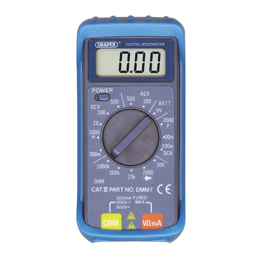
GETTING TO KNOW YOUR MULTIMETER (1) Function Selector. (5) V, , mA (Voltage, Resistance, Amperage) Jack Socket. (2) Power Switch. (6) Common Earth Jack Socket. (3) L.C.D. Screen. (4) Probes. UNPACKING: After removing the packing material, make sure the product is in perfect condition and that there are no visible damaged parts. -
Page 6: Assembly
GETTING TO KNOW YOUR MULTIMETER - OTHER METER MARKINGS Diode check. Indicates that the meter battery voltage has dropped excessively. Units of measuring current (AMPS). µA Units of measuring voltage (VOLTS). Units of measuring resistance (OHMS). Caution. Risk of electric shock. ASSEMBLY Remove the rubber case. -
Page 7: Operation And Use
OPERATION AND USE - WARNINGS: Each time before you use this analyser, inspect the test leads, connectors and probes for damage, e.g. cracks or breaks in the insulation. Any defective leads should be replaced immediately. If the value to be measured is not known, set the selector switch to the highest range and reduce until a satisfactory reading is obtained. -
Page 8: Maintenance
MAINTENANCE The fuse rarely needs replacing, and almost always a blown fuse is the result of an operator error. - WARNING: If the resistance to be measured is part of a circuit, turn off and disconnect the power and discharge all capacitors before measurement If the meter battery is in need of replacement (see Assembly section) the ‘... - Page 9 NOTES - 8 -...
- Page 10 NOTES - 9 -...
- Page 11 NOTES - 10 -...
- Page 12 ©Published by Draper Tools Limited. No part of this publication may be reproduced, stored in a retrieval system or transmitted in any form or by any means, electronic, mechanical photocopying, recording or otherwise without prior permission in writing from Draper Tools Ltd.
Need help?
Do you have a question about the Digital Multimeter and is the answer not in the manual?
Questions and answers
I wish to test the continuity of a heating element but cannot identify the required symbol.
The symbol for testing continuity on a Draper Digital Multimeter is the diode symbol (a triangle pointing to a line), which is used for both diode and continuity tests.
This answer is automatically generated
why doe my reading not go back to 000 but sticks at -009
The manual does not provide a direct explanation for this issue. However, possible causes could include improper calibration, residual charge in the circuit being measured, or a low battery. Try resetting the meter by turning it off and on, ensuring the test leads are not connected to a circuit, and replacing the battery if necessary. If the issue persists, consult the dealer or Draper Tools support.
This answer is automatically generated