
Subscribe to Our Youtube Channel
Related Manuals for Draper DMM11


Summary of Contents for Draper DMM11
- Page 1 AUTORANGING MULTIMETER STOCK No.59315 PART No.DMM11 • INSTRUCTIONS • IMPORTANT: PLEASE READ THESE INSTRUCTIONS CAREFULLY TO ENSURE THE SAFE AND EFFECTIVE USE OF THIS TOOL. 12/99...
-
Page 2: Specification
INTRODUCTION Autoranging Multimeter This multimeter is ideal for general electrical and automotive use. FEATURES 13 position rotary function and range selector. Recessed input terminals for added safety. Measures A.C./D.C. voltage, A.C./D.C. amps, frequency, resistance and capacitance. 200mA fuse protection. Audible continuity buzzer. Diode test facility. -
Page 3: Maintenance
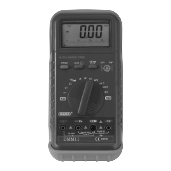
Fig 1. MAINTENANCE The fuse rarely needs replacing, and almost always a blown fuse is the result of operator error. (see warning on front page). If the meter battery is in need of replacement, ‘ ’ will appear on the display. ACCESSORIES PART No: YDMM7... - Page 4 KNOW YOUR MULTIMETER ✖✌ ✛✌ ✢✌ ✜✌ ✕✔✌ ✕✌ ✘✌ ✙✌ ✗✌ ✚✌ - 3-...
- Page 5 KNOW YOUR MULTIMETER 1. Autoranging Function Switch This switch is used to select the function and desired range. 2. Display LCD display unit. 3. ‘COM’ Jack Socket Plug in the black (negative) test lead. 4. ‘V/ /F (voltage/resistance/frequency) Jack Socket (max 200mA) Plug in the red (positive) test lead for all voltage, resistance and amperage (max 200mA) measurements.
-
Page 6: Operation
OPERATION WARNINGS: Before you use the instrument, inspect the test leads, connectors and probes for damage e.g. cracks or breaks in the insulation. Replace any defective leads before use. If the voltage to be measured is not known, set the selector switch to the highest range and reduce until a satisfactory reading is obtained. - Page 7 Transistor hFE Test 1. Set the selector switch to the hFE position. 2. Determine whether the transistor is NPN or PNP. 3. Locate the emitter (E), base (B) or (C)and collect legs into the correct holes in the socket on the front panel.
- Page 8 ©Published by Draper Tools Ltd. No part of this publication may be reproduced, stored in a retrieval system or transmitted in any form or by any means, electronic, mechanical photocopying, recording or otherwise without prior permission in writing from Draper Tools Ltd.
Need help?
Do you have a question about the DMM11 and is the answer not in the manual?
Questions and answers