Toshiba TECRA A11 User Manual
Portable personal computer
Hide thumbs
Also See for TECRA A11:
- User manual (247 pages) ,
- User manual (230 pages) ,
- Maintenance manual (462 pages)
Table of Contents
Advertisement
Advertisement
Chapters
Table of Contents

Related Manuals for Toshiba TECRA A11


Summary of Contents for Toshiba TECRA A11
- Page 1 User’s Manual TECRA A11/S11/P11/ Satellite Pro S500 Series...
-
Page 2: Table Of Contents
Table of Contents Copyright..........vi Disclaimer . - Page 3 Special features ......... . 3-6 TOSHIBA Value Added Package ......3-9 Utilities and Applications.
- Page 4 TOSHIBA support ........
- Page 5 TECRA A11/S11/P11/Satellite Pro S500 LCD*6........... G-3 Graphics Processor Unit ("GPU")*7...
-
Page 6: Copyright
Intel Corporation. Windows, Microsoft and Windows logo are registered trademarks of Microsoft Corporation. Bluetooth is a trademark owned by its proprietor and used by TOSHIBA under license. Photo CD is a trademark of Eastman Kodak Company. Memory Stick, Memory Stick PRO, Memory Stick PRO Duo and i.LINK are trademarks or registered trademarks of Sony Corporation. -
Page 7: Fcc Information
Only peripherals complying with the FCC class B limits may be attached to this equipment. Operation with non-compliant peripherals or peripherals not recommended by TOSHIBA is likely to result in interference to radio and TV reception. Shielded cables must be used between the external devices and the computer’s external monitor port, Universal Serial Bus... -
Page 8: Eu Conformity Statement
Radio Interference Regulation of the Canadian Department of Communications. Note that Canadian Department of Communications (DOC) regulations provide, that changes or modifications not expressly approved by TOSHIBA Corporation could void your authority to operate this equipment. User’s Manual viii... -
Page 9: Modem Warning Notice
TECRA A11/S11/P11/Satellite Pro S500 This Class B digital apparatus meets all requirements of the Canadian Interference-Causng Equipment Regulations. Cet appareil numérique de la class B respecte toutes les exgences du Règlement sur le matériel brouileur du Canada. Modem warning notice This information is applicable to the models equipped with a built-in modem. -
Page 10: Japan Regulations
TECRA A11/S11/P11/Satellite Pro S500 Japan regulations Region selection If you are using the computer in Japan, technical regulations described in the Telecommunications Business Law require that you select the Japan region mode. It is illegal to use the modem in Japan with any other selection. -
Page 11: Type Of Service
FCC. In the event repairs are ever needed on your modem, they should be performed by TOSHIBA Corporation or an authorized representative of TOSHIBA Corporation. -
Page 12: Instructions For Ic Cs-03 Certified Equipment
TECRA A11/S11/P11/Satellite Pro S500 Fax branding The Telephone Consumer Protection Act of 1991 makes it unlawful for any person to use a computer or other electronic device to send any message via a telephone fax machine unless such message clearly contains in a... -
Page 13: Notes For Users In Australia And New Zealand
TECRA A11/S11/P11/Satellite Pro S500 The Ringer Equivalence Number (REN) assigned to each terminal device provides an indication of the maximum number of terminals allowed to be connected to a telephone interface. The termination on an interface may consist of any combination of devices subject only to the requirement that the sum of the Ringer Equivalence Numbers of all the devices does not exceed 5. - Page 14 TECRA A11/S11/P11/Satellite Pro S500 Notes for use of this device in New Zealand ■ The grant of a Telepermit for a device in no way indicates Telecom acceptance of responsibility for the correct operation of that device under all operating conditions. In particular the higher speeds at which...
-
Page 15: General Conditions
TECRA A11/S11/P11/Satellite Pro S500 ■ When used in the Auto Answer mode, the S0 register must be set with a value of 3 or 4. This ensures: a/ A person calling your modem will hear a short burst of ringing before the modem answers. -
Page 16: Following Information Is Only Valid For Eu-Member States
For more detailed information about the collection and recycling programmes available in your country, please visit our website (http://eu.computers.toshiba-europe.com) or contact your local city office or the shop where you purchased the product. Disposal of batteries and/or accumulators... -
Page 17: Disposing Of The Computer And The Computer's Batteries
TECRA A11/S11/P11/Satellite Pro S500 Disposing of the computer and the computer's batteries ■ Discard this computer in accordance with applicable laws and regulations. For further information, contact your local government. ■ This computer contains rechargeable batteries. After repeated use, the batteries will finally lose their ability to hold a charge and you will need to replace them. -
Page 18: Optical Disc Drive Safety Instructions
TECRA A11/S11/P11/Satellite Pro S500 Optical disc drive safety instructions Be sure to check the international precautions at the end of this section. TEAC DVD-ROM drive DV-28S ■ The DVD-ROM drive model employs a laser system. To ensure proper use of this product, please read this instruction manual carefully and retain for future reference. - Page 19 TECRA A11/S11/P11/Satellite Pro S500 TEAC DVD Super Multi with Double Layer Recording DV-W28S ■ The DVD Super Multi drive model employs a laser system. To ensure proper use of this product, please read this instruction manual carefully and retain for future reference. Should the unit ever require maintenance, contact an authorized service location.
- Page 20 TECRA A11/S11/P11/Satellite Pro S500 Panasonic Communications DVD Super Multi with Double Layer Recording UJ890 ■ The DVD Super Multi drive model employs a laser system. To ensure proper use of this product, please read this instruction manual carefully and retain for future reference. Should the unit ever require maintenance, contact an authorized service location.
- Page 21 TECRA A11/S11/P11/Satellite Pro S500 HITACHI LG DVD Super Multi with Double Layer Recording GT20N ■ The DVD Super Multi drive model employs a laser system. To ensure proper use of this product, please read this instruction manual carefully and retain for future reference. Should the unit ever require maintenance, contact an authorized service location.
-
Page 22: International Precautions
TECRA A11/S11/P11/Satellite Pro S500 International precautions CAUTION: This appliance contains a laser system and is classified as a “CLASS 1 LASER PRODUCT.” To use this model properly, read the instruction manual carefully and keep this manual for your future reference. In case of any trouble with this model, please contact your nearest “AUTHORIZED service... - Page 23 TECRA A11/S11/P11/Satellite Pro S500 OBS! Apparaten innehåller laserkomponent som avger laserstråining överstigande gränsen för laserklass 1. VAROITUS. Suojakoteloa si saa avata. Laite sisältää laserdiodin, joka lähetää näkymätöntä silmilie vaarallista lasersäteilyä. CAUTION: USE OF CONTROLS OR ADJUSTMENTS OR PERFORMANCE OF PROCEDURES OTHER THAN THOSE SPECIFIED IN THE OWNER’S...
-
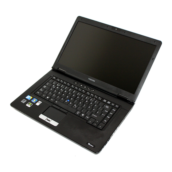
Page 24: Preface
Preface Congratulations on your purchase of the TECRA A11/S11/P11Satellite Pro S500 Series computer. This powerful notebook computer provides excellent expansion capability, includes multimedia functionality, and is designed to provide years of reliable, high-performance computing. This manual tells how to set up and begin using your TECRA A11/S11/P11Satellite Pro S500 computer. - Page 25 TECRA A11/S11/P11/Satellite Pro S500 Icons Icons identify ports, dials, and other parts of your computer. The indicator panel also uses icons to identify the components it is providing information Keys The keyboard keys are used in the text to describe many computer operations.
- Page 26 TECRA A11/S11/P11/Satellite Pro S500 Terminology This term is defined in this document as follows: Start The word "Start" refers to the " " button in Windows 7. HDD or Hard disk Some models are equipped with a "Solid State drive Drive (SSD)"...
-
Page 27: General Precautions
General Precautions TOSHIBA computers are designed to optimize safety, minimize strain and withstand the rigors of portability. However, certain precautions should be observed to further reduce the risk of personal injury or damage to the computer. Be certain to read the general precautions below and to note the cautions included in the text of the manual. -
Page 28: Creating A Computer-Friendly Environment
TECRA A11/S11/P11/Satellite Pro S500 Creating a computer-friendly environment Place the computer on a flat surface that is large enough for the computer and any other items you are using, such as a printer. Leave enough space around the computer and other equipment to provide adequate ventilation. -
Page 29: Pressure Or Impact Damage
TECRA A11/S11/P11/Satellite Pro S500 Pressure or impact damage Do not apply heavy pressure to the computer or subject it to any form of strong impact as this can damage the computer's components or otherwise cause it to malfunction. PC Card/ExpressCard overheating... -
Page 30: Equipment Checklist
Some of the features described in this manual may not function properly if you use an operating system that was not pre-installed by TOSHIBA. Equipment checklist Carefully unpack your computer, taking care to save the box and packaging materials for future use. - Page 31 TOSHIBA eco Utility ■ Fingerprint Utility ■ Windows Mobility Center ■ Online Manual ■ TECRA A11/S11/P11Satellite Pro S500 User's Manual (This manual) * You may not have all the softwares listed above depending on the model you purchased. User’s Manual...
- Page 32 Getting Started Getting Started ■ All users should be sure to read the section Starting up for the first time. ■ Be sure to read the enclosed Instruction Manual for Safety and Comfort for information on the safe and proper use of this computer. It is intended to help you be more comfortable and productive while using a notebook computer.
-
Page 33: Connecting The Ac Adaptor
■ Always use the TOSHIBA AC adaptor that was included with your computer, or use AC adaptors specified by TOSHIBA to avoid any risk of fire or other damage to the computer. Use of an incompatible AC adaptor could cause fire or damage to the computer possibly resulting in serious injury. - Page 34 Getting Started 1. Connect the power cord to the AC adaptor. Figure 1-1 Connecting the power cord to the AC adaptor (2-pin plug) Figure 1-2 Connecting the power cord to the AC adaptor (3-pin plug) Either a 2-pin or 3-pin adaptor/cord will be included with the computer depending on the model.
-
Page 35: Opening The Display
Getting Started Opening the display The display panel can be opened to a wide range of angles for optimal viewing. While holding down the palm rest with one hand so that the main body of the computer is not raised, slowly lift the display panel - this will allow the angle of the display panel to be adjusted to provide optimum clarity. -
Page 36: Turning On The Power
Getting Started Turning on the power This section describes how to turn on the power - the Power indicator will then indicate the status. Please refer to the Monitoring of power condition section in Chapter 6, Power and Power-Up Modes for more information. ■... -
Page 37: Turning Off The Power
Getting Started Turning off the power The power can be turned off in one of three modes, either Shut Down Mode, Hibernation Mode or Sleep Mode. Shut Down Mode When you turn off the power in Shut Down Mode no data will be saved and the computer will boot to the operating system's main screen the next time it is turned on. - Page 38 Getting Started ■ Before entering Sleep Mode, be sure to save your data. ■ Do not install or remove a memory module while the computer is in Sleep Mode. The computer or the memory module could be damaged. ■ Do not remove the battery pack while the computer is in Sleep Mode (unless the computer is connected to an AC power source).
-
Page 39: Hibernation Mode
Getting Started When you turn the power back on, you can continue where you left when you shut down the computer. ■ When the computer is in Sleep Mode, the power indicator will blink orange. ■ If you are operating the computer on battery power, you can lengthen the overall operating time by turning it off into Hibernation Mode - Sleep Mode will consume more power while the computer is off. -
Page 40: Restarting The Computer
Getting Started Starting Hibernation Mode You can also enable Hibernation Mode by pressing FN + F4 - please refer to Chapter 5, Keyboard, for further details. To enter Hibernation Mode, follow the steps below. 1. Click Start. 2. Point to the arrow icon ( ) and then select Hibernate from the menu. -
Page 41: System Recovery Options
Getting Started ■ Press the power button and hold it down for five seconds. Once the computer has turned itself off, wait between ten and fifteen seconds before turning the power on again by pressing the power button. System Recovery Options There is a hidden partition allocated on the hard disk drive for the System Recovery Options. -
Page 42: System Recovery
Getting Started System Recovery This section describes the creation of Recovery Media and their use. Creating Recovery Media This section describes how to create Recovery Media. ■ Be sure to connect the AC adaptor when you create Recovery Media. ■ Be sure to close all other software programs except the Recovery Media Creator. - Page 43 Getting Started 4. Double click the Recovery Media Creator icon on the Windows 7 desktop, or select the application from Start Menu. 5. After Recovery Media Creator starts, select the type of media and the title you wish to copy, and then click the Create button. Restoring the pre-installed software from the Recovery hard disk drive A portion of the total hard disk drive space is configured as a hidden...
- Page 44 4. A menu will be displayed from which you should follow the on-screen instructions. When drivers/utilities are installed, you can setup the respective drivers/utilities from the following place. To open the setup files, Click Start -> All Programs -> TOSHIBA -> Applications and Drivers. User’s Manual 1-15...
-
Page 45: Chapter 2 The Grand Tour
Chapter 2 The Grand Tour This chapter identifies the various components of the computer - it is recommended that you become familiar with each before you operate the computer. Legal Footnote (Non-applicable Icons) For more information regarding Non-applicable Icons, please refer to the Legal Footnotes section in Appendix G or click the *1 above. - Page 46 The Grand Tour System indicators These LED indicators allow you to monitor the status of various computer functions and are described in more detail within the System indicators section. Bridge media slot This slot lets you insert an SD™/SDHC™ memory card, miniSD™/microSD™ Card, ®...
-
Page 47: Left Side
The Grand Tour Stereo speakers The speakers emit sound generated by your software as well as audio alarms, such as low battery condition, generated by the system. Microphone A built-in microphone allows you to import and record sounds for your application - please refer to the Sound System section in Chapter 4,... - Page 48 The Grand Tour Please note that it is not possible to confirm the operation of all functions of all USB devices that are available. In view of this it may be noted that some functions associated with a specific device might not operate properly. Cooling vents The cooling vents help keep the processor from overheating.
-
Page 49: Right Side
The Grand Tour Right side The following figure shows the computer’s right side. 1. Smart Card slot* 4. Optical disc drive* 2. Headphone jack 5. Universal Serial Bus (USB 2.0) ports 3. Microphone jack * Provided with some models. Product appearance depends on the model you purchased. Figure 2-3 The right side of the computer Smart Card slot This slot can accommodate a single Smart Card... -
Page 50: Back
The Grand Tour Please note that it is not possible to confirm the operation of all functions of all USB devices that are available. In view of this it may be noted that some functions associated with a specific device might not operate properly. Back The following figure shows the computer’s back. - Page 51 The Grand Tour DC IN 15V jack The AC adaptor connects to this jack in order to power the computer and charge its internal batteries. Please note that you should only use the model of AC adaptor supplied with the computer at the time of purchase - using the wrong AC adaptor can cause damage to the computer.
-
Page 52: Underside
Options. Some models are equipped with a Docking port. ■ Only the TOSHIBA Express Port Replicator can be used with this computer. Do not attempt to use any other Port Replicator. ■ Keep foreign objects out of the docking port. A pin or similar object can damage the computer's circuitry. - Page 53 The Grand Tour Memory module slot The memory module slot allows for the installation, replacement and removal of additional memory module. Refer to the Additional memory module section in Chapter 3, Hardware, Utilities and Options. Battery release latch Slide and hold this latch into its 'Unlock' position in order to release the battery pack for removal.
-
Page 54: Front With The Display Open
15. Bluetooth antenna (not shown) 7. Power button 16. AccuPoint* 8. eco button 17. AccuPoint control buttons* 9. TOSHIBA Presentation button * Provided with some models. Product appearance depends on the model you purchased. Wireless LAN Some computers in this series are equipped with antennas the Wireless LAN antennas. - Page 55 Utility. This button changes "On" and "Off" of eco Mode. When eco Mode is "On", the icon turns green. When eco Mode is "Off", the icon turns gray. The TOSHIBA eco Utility is not supported by ® Windows XP operating system.
- Page 56 The Grand Tour volume down button Press this button to decrease the volume. volume up button Press this button to increase the volume. Keyboard Your computer may intergrated with two kinds of keyboards: A4 size keyboard which provides the embedded numeric overlay keys, dedicated cursor control overlay keys, and Keys;...
-
Page 57: Indicators
The Grand Tour AccuPoint control Control buttons below the keyboard let you select buttons menu items or manipulate text and graphics designated by the on-screen pointer. Refer to the Using the AccuPoint section in Chapter 4, Operating Basics. Some models are equipped with a AccuPoint control buttons. - Page 58 The Grand Tour DC IN The DC IN indicator normally glows green when power is being correctly supplied from the AC power adaptor. However, If the output voltage from the adaptor is abnormal, or if the computer's power supply malfunctions, this indicator will flash orange.
-
Page 59: Keyboard Indicators
The Grand Tour Wireless WAN The Wireless WAN indicator glows or blinks blue when the Wireless WAN function is on. The indicator will glow or blink in order to indicate the connection status of the Wireless WAN function. A Wireless WAN module must be installed to use this function. - Page 60 The Grand Tour 1. Arrow mode indicator 2. Numeric mode indicator Figure 2-10 Keypad overlay indicators Arrow mode When the Arrow mode indicator lights green, you can use the gray labeled keys on the keypad overlay as cursor keys. Please refer to the Keypad overlay for A4 size keyboard section in Chapter 5, The Keyboard for more information.
-
Page 61: Optical Disc Drives
The Grand Tour 2. NUM LOCK indicator 1. CAPS LOCK indicator Figure 2-11 Keypad indicators CAPS LOCK This indicator glows green when letter keys are locked into their uppercase format. NUM LOCK When the NUM LOCK indicator glows, you can use the number keys on the keyboard for number entry. -
Page 62: Writable Discs
Writable discs This section describes the types of writable CD/DVD discs. Check the specifications of your drive to see the types of discs it can write. Use TOSHIBA Disc Creator to write compact discs. Refer to Chapter 4, Operating Basics. - Page 63 The Grand Tour DVD-ROM drive The full-size DVD-ROM drive module lets you run either 12 cm (4.72") or 8 cm (3.15") CD/DVDs without using an adaptor. The read speed is slower at the center of a disc and faster at the outer edge.
-
Page 64: Ac Adaptor
Always use the TOSHIBA AC adaptor that was included with your computer, or use AC adaptors specified by TOSHIBA to avoid any risk of fire or other damage to the computer. Use of an incompatible AC adaptor could cause fire or damage to the computer possibly resulting in serious injury. -
Page 65: Chapter 3 Hardware, Utilities And Options
Your computer is equipped with one processor and processor type varies depending on model. To check which type of processor is included in your model, open the TOSHIBA PC Diagnostic Tool Utility by clicking Start -> All Programs -> TOSHIBA -> Utilities -> PC Diagnostic Tool. - Page 66 Hardware, Utilities and Options Memory Memory slots 1 GB, 2 GB or 4 GB memory modules can be installed in the computer's two memory slots for a maximum of 8,192MB system memory. This computer can be equipped with memory modules of a maximum size of 8,192MB. The actual amount of useable system memory will be less than the installed memory modules.
- Page 67 Hardware, Utilities and Options Legal Footnote (Battery Life) For more information regarding Battery Life, please refer to the Legal Footnotes section in Appendix G or click the *4 above. RTC battery The internal RTC battery backs up the Real Time Clock (RTC) and calendar.
-
Page 68: Optical Disc Drive
Hardware, Utilities and Options ■ In this manual, the word "HDD" or "Hard disk drive" also refers to the SSD unless otherwise stated. ■ SSD is a large-capacity storage media which uses Solid-State Memory in place of a magnetic disk of the hard disk. ■... - Page 69 You can use it for video chatting or video conferences using a communication tool such as Windows Live Messenger. TOSHIBA Web Camera Application will help you to add various video effects to your video or photograph.
-
Page 70: Special Features
Footnotes section in Appendix G or click the *8 above. Special features The following features are either unique to TOSHIBA computers or are advanced features which make the computer more convenient to use. Access each function using the following procedures. - Page 71 Hardware, Utilities and Options Display automatic This feature automatically cuts off power to the computer's display panel when there is no power off keyboard input for a specified time, with power being restored the next time a key is pressed. This can be specified in the Power Options.
- Page 72 The TOSHIBA HDD Protection function does not guarantee that the hard disk drive will not be damaged. ■ TOSHIBA HDD Protection cannot be used in models that are equipped with SSD. Hibernation Mode This feature lets you turn off the power to the computer without exiting from your software.
-
Page 73: Toshiba Value Added Package
Refer to Appendix F, TOSHIBA PC Health Monitor. TOSHIBA Value Added Package This section describes the TOSHIBA Component features pre-installed on the computer. TOSHIBA Power TOSHIBA Power Saver provides you with the Saver features of more various power supply managements. -
Page 74: Utilities And Applications
Hardware, Utilities and Options TOSHIBA Button Support cannot be used in models that are not equipped with eco button and TOSHIBA Presentation button. TOSHIBA Zooming This utility allows you to enlarge or reduce the Utility icon size on the Windows Desktop, or the zoom factor associated with specific supported applications. - Page 75 This software is provided for playback of DVD Player Video. It has an on-screen interface and functions. Click Start -> All Programs -> TOSHIBA DVD PLAYER -> TOSHIBA DVD PLAYER. For details on how to use TOSHIBA DVD PLAYER, see the help file. User’s Manual 3-11...
- Page 76 Video. Power-saving features may interfere with smooth playback. ■ If you see the screen blinking while playing DVD with subtitle on at Media Player, please use TOSHIBA DVD Player or Media Center to play DVD. Bluetooth Stack for This software enables communication between...
- Page 77 Alert Utility the Disk Drive operating status and execute the system backup. To access the utility, click Start -> All Programs -> TOSHIBA -> Utilities -> HDD SSD Alert. TOSHIBA Service This application allows your computer to Station automatically search for TOSHIBA software...
- Page 78 TPM. To enable TPM through the BIOS setup: 1. Turn on the computer while pressing the F2 key. When the TOSHIBA Leading Innovation >>> screen appears, release the F2 key. 2. Set the TPM in the Security tab to Enabled.
-
Page 79: Optional Devices
The computer is equipped with a single ExpressCard slot into which any ExpressCard device that meets industry standards, either manufactured by TOSHIBA or another vendor, can be installed. The slot supports hot plug connection and utilizes the PCI Express interface that supports the reading and writing of data at a theoretical maximum rate of 2.5Gbps. -
Page 80: Removing An Expresscard
Hardware, Utilities and Options To insert an ExpressCard, follow the steps as detailed below: 1. Press the Dummy card in order to eject the Dummy card partially out of the computer. 2. Grasp the Dummy card and draw it. 3. Insert the ExpressCard into the ExpressCard slot on the side of the computer. -
Page 81: Inserting A Pc Card
The computer is equipped with a single PC Card slot that can accommodate a Type II format card. Any PC Card that meets industry standards, either manufactured by TOSHIBA or another vendor, can be installed as the slot supports 16-bit PC Cards and 32-bit CardBus cards. -
Page 82: Removing A Pc Card
Hardware, Utilities and Options 3. After inserting the PC Card you should refer to its documentation and also check the configuration in Windows in order to ensure that it is correct. Removing a PC Card To remove a PC Card, follow the steps as detailed below: 1. -
Page 83: Inserting A Smart Card
Hardware, Utilities and Options Inserting a Smart Card The Smart Card slot is located on the right side of the computer. The Windows hot-install feature allows you to insert a Smart Card while the computer is turned on. To install a Smart Card, follow the steps as detailed below: 1. -
Page 84: Bridge Media Slot
Hardware, Utilities and Options Removing a Smart Card To remove a Smart Card, follow the steps as detailed below: 1. Open the Safely Remove Hardware icon on the Windows Taskbar. ■ Before removing the Smart Card, confirm that the Smart Card is not working with any program or system. -
Page 85: Memory Media
Hardware, Utilities and Options ■ This Bridge media slot supports the following memory media. ■ Secure Digital (SD) Card (SD memory card, SDHC memory card, miniSD Card, microSD Card) ■ Memory Stick (Memory Stick, Memory Stick PRO, Memory Stick PRO Duo) ■... -
Page 86: Memory Card Care
Hardware, Utilities and Options ■ The maximum capacity of SD memory cards is 2GB. The maximum capacity of SDHC memory cards is 32GB. Card Type Capacities 8MB, 16MB, 32MB, 64MB, 128MB, 256MB, 512MB, 1GB, 2GB SDHC 4GB, 8GB, 16GB, 32GB Memory media format New media cards are formatted according to specific standards. -
Page 87: Inserting A Memory Media
Hardware, Utilities and Options ■ Do not remove a card while read/write is in progress. For more details on using memory cards, see manuals accompanying the cards. About the write-protect The following memory media have a function for protect. ■ SD Card (SD memory card, SDHC memory card) ■... -
Page 88: Removing A Memory Media
Hardware, Utilities and Options ■ Make sure memory media is oriented properly before you insert it. If you insert the media in wrong direction, you may not be able to remove ■ When inserting memory media, do not touch the metal contacts. You could expose the storage area to static electricity, which can destroy data. - Page 89 You can access the inserted memory modules efficiently in dual channel. ■ Use only memory modules approved by TOSHIBA. ■ Do not try to install or remove a memory module under the following conditions.
-
Page 90: Installing A Memory Module
Hardware, Utilities and Options Point to note about memory module error If you install a memory module that is not compatible with the computer, the Power indicator will flashes (on for 0.5 seconds, off for 0.5 seconds) in the following ways; ■... - Page 91 Hardware, Utilities and Options 6. Slide your fingernail or a thin object under the cover and lift it off. 1. Memory module cover 2. Screw Figure 3-10 Removing the memory module cover 7. Align the notch of the memory module with that of the memory slot and gently insert the module into the slot at about a 45 degree angle before holding it down until the latches on either side snap into place.
-
Page 92: Removing A Memory Module
Hardware, Utilities and Options ■ The slot A is reserved for the first memory module. Use the slot B for expanded memory. If only one module is installed, use the slot A. When inserting or removing memory modules, use the A and B marked on the computer chassis to determine which slot is A and which is B. - Page 93 Hardware, Utilities and Options 5. Loosen the one screw securing the memory module cover in place - please note that this screw is attached to the cover in order to prevent it from being lost. 6. Slide your fingernail or a thin object under the cover and lift it off. 7.
-
Page 94: External Monitor
Hardware, Utilities and Options External monitor An external analog monitor can be connected to the external monitor port on the computer. To connect a monitor, follow the steps as detailed below: Connecting the monitor cable 1. Turn the computer's power off. 2. -
Page 95: Mini Displayport
Hardware, Utilities and Options Mini DisplayPort With a suitable adapter (such as the "Mini DisplayPort to HDMI adapter" or "Mini DisplayPort to DVI adapter"), this port enables you to connect an external monitor. Connecting the Mini DisplayPort 1. Plug the Mini DisplayPort connector of the adapter into the Mini DisplayPort on your computer. -
Page 96: Usb Fdd Kit
Hardware, Utilities and Options USB FDD Kit The USB floppy diskette drive accommodates either a 1.44MB or 720KB floppy diskette and connects to one of the computer's USB ports. 1. USB connector 3. Floppy diskette slot 2. Disk-In-Use Indicator 4. Eject button Figure 3-16 The USB floppy diskette drive Connecting the USB floppy diskette drive To connect the drive, plug the floppy diskette drive’s USB connector into a... - Page 97 Hardware, Utilities and Options If you connect the USB floppy diskette drive after the computer has already been turned on, it will take about ten seconds for it to be recognized by the computer. Do not attempt to disconnect and reconnect the drive before this period has elapsed.
-
Page 98: Disconnecting An Esata Device
Hardware, Utilities and Options ■ A connected eSATA device may not be recognized if it is connected to the computer's eSATA/USB combo port while the computer is in Sleep Mode or Hibernation Mode. If this occurs, disconnect the eSATA device and then reconnect the device while the computer is turned on. -
Page 99: Toshiba Express Port Replicator
Figure 3-19 Connecting the serial connector to the serial port TOSHIBA Express Port Replicator In addition to the ports available on the computer, the TOSHIBA Express Port Replicator also provides several kinds of ports. The TOSHIBA Express Port Replicator connects directly to the docking interface on the underside of the computer. -
Page 100: Security Lock
■ Set the TOSHIBA Express Port Replicator's Slide Adjuster to SLIDE position #3 or #5 when connecting this computer to the TOSHIBA Express Port Replicator. Refer to the TOSHIBA Express Port Replicator User's Manual for more details on connection methods. -
Page 101: Optional Accessories
TOSHIBA Express The TOSHIBA Express Port Replicator provides Port Replicator the ports available on the computer in addition to a digital visual interface (DVI) port, External monitor port, four Universal Serial Bus ports (USB 2.0) and a LAN jack. -
Page 102: Chapter 4 Operating Basics
This chapter describes the basic operations of your computer, highlights the precautions that should be taken when using it. TOSHIBA Dual Pointing Device Some models are equipped with a dual point system: a Touch Pad and an AccuPoint pointing stick. -
Page 103: Using The Accupoint
Operating Basics The two buttons below the Touch Pad are used like the buttons on a standard mouse - press the left button to select a menu item or to manipulate text or graphics designated by the pointer, and press the right button to display a menu or other function depending on the software you are using. -
Page 104: Using The Fingerprint Sensor
Operating Basics Replacing the cap The AccuPoint cap is an expendable item that should be replaced after prolonged use. The spare AccuPoint cap is supplied with some models. 1. To remove the AccuPoint cap, firmly pinch the cap and pull it straight 1. -
Page 105: Points To Note About The Fingerprint Sensor
Operating Basics How to Swipe your Finger Using the following steps when swiping fingers for fingerprint registration or authentication will help to minimize authentication failures: Align the first joint of the finger to the center of the sensor. Lightly touch the sensor and swipe finger levelly towards you until the sensor surface becomes visible. - Page 106 Operating Basics ■ Do not paste stickers or write on the sensor. ■ Do not touch the sensor with a finger or any other object which may have a build-up of static electricity on it. Observe the following before you place your finger on the sensor whether for fingerprint enrollment/registration or recognition.
-
Page 107: Fingerprint Utility Limitations
TOSHIBA does not guarantee that the fingerprint utility technology will be completely secure or error-free, or that it will accurately screen out unauthorized users at all times. TOSHIBA is not liable for any failure or damage that might arise out of the use of the fingerprint software. - Page 108 Delete the fingerprint data for the currently logged in user 1. Click Start -> All Programs -> TOSHIBA -> Utilities -> TOSHIBA Fingerprint Utility, or double click the utility icon in the Taskbar. 2. Swipe your finger across the fingerprint sensor.
-
Page 109: Windows Logon Via Fingerprint Authentication
Operating Basics 8. "Are you sure you want to quit?" is displayed. Click OK. It will be returned to the TOSHIBA Fingerprint Utility main menu. Windows Logon via Fingerprint Authentication In place of the usual Windows logon by ID and password, fingerprint authentication also allows logon to Windows. -
Page 110: How To Enable Fingerprint Boot Authentication And Single Sign-On Feature
How to Enable Fingerprint boot authentication and Single Sign-On feature It is necessary to first enroll your fingerprint with the TOSHIBA Fingerprint Utility prior to enabling and configuring the boot authentication and Single Sign-On feature. You should check that your fingerprint is enrolled before configuring the settings. -
Page 111: Web Camera
You can use it for video chatting or video conferences using a communication tool such as Windows Live Messenger. TOSHIBA Web Camera Application will help you to add various video effects to your video or photograph. -
Page 112: Using The Toshiba Face Recognition
Toshiba does not guarantee that the face recognition utility will accurately screen out unauthorized users at all times. Toshiba is not liable for any failure or damage that might arise out of the use of the face recognition software or utility. - Page 113 Take a picture for facial verification purposes, and register the data needed when you log in. To register the data needed when you log in, follow the steps as described below: 1. To launch this utility, click Start -> All Programs -> TOSHIBA -> Utilities -> Face Recognition. ■...
- Page 114 How to launch the help file For further information on this utility, please refer to help file. 1. To launch the help file, click Start -> All Programs -> TOSHIBA -> Utilities -> Face Recognition Help. Windows Logon via TOSHIBA Face Recognition This section explains how to login to Windows with TOSHIBA Face Recognition.
-
Page 115: Using Optical Disc Drives
Operating Basics 5. Verification will be performed. If the authentication is successful, the image data taken in step 4 will be faded in and placed over one another. ■ If an error occurs during authentication, you will be returned to the Select Tiles screen. -
Page 116: Loading Discs
Operating Basics Loading discs To load CD/DVDs, follow the steps as detailed below: 1. When the computer’s power is on, press the eject button to open the disc tray slightly. 2. Grasp the disc tray gently and pull until it is fully opened. 1. - Page 117 Operating Basics When the disc tray is fully opened, the edge of the computer will extend slightly over the CD/DVD tray. Therefore, you will need to turn the CD/DVD at an angle when you place it in the disc tray. After seating the CD/DVD, however, make sure it lies flat.
-
Page 118: Removing Discs
Operating Basics Removing discs To remove the CD/DVD, follow the steps as detailed below: Do not press the eject button while the computer is accessing the media drive. Wait for the optical disc drive indicator to go out before you open the disc tray. -
Page 119: Writing Cd/Dvds On Dvd Super Multi Drives
Do not turn off the power to the optical disc drive while the computer is accessing it as this may cause you to lose data. ■ To write data to CD-R/-RW media, use the TOSHIBA Disc Creator feature that is installed on your computer. User’s Manual... -
Page 120: Important Message
Layer), DVD-RW, DVD+R, DVD+R (Double Layer), DVD+RW or DVD- RAM media, however, it must be noted that disc quality can affect write or rewrite success rates. Please also be aware that in no event does TOSHIBA guarantee the operation, quality or performance of any disc. User’s Manual 4-19... - Page 121 Operating Basics CD-R: TAIYO YUDEN CO., Ltd. MITSUBISHI KAGAKU MEDIA CO., LTD. Hitachi Maxell,Ltd. CD-RW: (Multi-Speed and High-Speed) MITSUBISHI KAGAKU MEDIA CO., LTD. CD-RW: (Ultra-Speed) MITSUBISHI KAGAKU MEDIA CO., LTD. DVD-R: DVD Specifications for Recordable Disc for General Version 2.0 TAIYO YUDEN Co.,Ltd.
- Page 122 Operating Basics ■ DVD Super Multi drive cannot use discs that allow writing faster than 16x speed (DVD-R and DVD+R media), 8x speed (DVD-R (Dual Layer), DVD+RW and DVD+R (Double Layer) media), 6x speed (DVD- RW media), 5x speed (DVD-RAM media). ■...
-
Page 123: When Writing Or Rewriting
CD/DVD - do not try to write from shared devices such as a server or any other network device. ■ Writing with software other than TOSHIBA Disc Creator has not been confirmed, therefore operation with other software applications cannot be guaranteed. -
Page 124: Toshiba Disc Creator
DVD-R, DVD-R (Dual Layer), DVD-RW, DVD+R, DVD+R (Double Layer) or DVD+RW media. ■ Do not use the 'Disc Backup' function of TOSHIBA Disc Creator in order to copy DVD Video or DVD-ROM material that has copyright protection. ■... -
Page 125: Media Care
Operating Basics ■ TOSHIBA Disc Creator does not support recording to DVD-RAM discs - to achieve this you should use Windows Explorer or another similar utility. ■ When you back up a DVD disc, be sure that the source drive supports... -
Page 126: Sound System
Operating Basics 4. Hold the CD or DVD by its outside edge or the edge on the center hole - any fingerprints on the surface of the disc can prevent the drive from properly reading data. 5. Do not expose the CD or DVD to direct sunlight, extreme heat or cold. 6. -
Page 127: Microphone Level
Operating Basics Volume Mixer The Volume Mixer utility lets you control the audio volume for playback of devices and applications under Windows. ■ To launch the Volume Mixer utility, right click on the speaker icon on the Taskbar, and select Open Volume Mixer from the sub menu. ■... -
Page 128: Power Management
5. On the Advanced tab, select “2 channel, 16 bit, 48000 Hz (DVD Quality)” in the pull-down menu of the Default Format pane. 6. On the TOSHIBA Mic Effect tab, select the Enable Echo Canceller check box, and click Apply. -
Page 129: Modem
Check the specified areas carefully before using it. To select a region, follow the steps as detailed below: 1. Click Start -> All Programs -> TOSHIBA -> Networking -> Modem Region Select. If it is available, do not use the Country/Region Select function included as... -
Page 130: Properties Menu
Operating Basics 4. Select either a region from the region menu or a telephony location from the sub-menu. ■ When you click a region it becomes the modem's default selection for any new dialling locations that are created within the Windows Control Panel (Phone and Modem Options). - Page 131 Operating Basics ■ Connection to any communication line other than an analog phone line could cause a computer system failure. ■ Connect the built-in modem only to ordinary analog phone lines. ■ Never connect the built-in modem to a digital line (ISDN). ■...
-
Page 132: Wireless Communications
Operating Basics Wireless communications The computer’s wireless communication function supports some wireless communication devices. Only some models are equipped with both Wireless LAN and Bluetooth functions. ■ Do not use the Wireless LAN (Wi-Fi) or Bluetooth functionalities near a microwave oven or in areas subject to radio interference or magnetic fields. -
Page 133: Worldwide Operation
■ TOSHIBA is not liable for the loss of data due to eavesdropping or illegal access through the wireless LAN and the damage thereof. Bluetooth wireless technology... -
Page 134: Bluetooth Stack For Windows By Toshiba
This Bluetooth Stack is based on the Bluetooth Version 1.1/1.2/2.0+EDR/2.1+EDR specification. However, TOSHIBA cannot confirm the compatibility between any computing products and/or other electronic devices that use Bluetooth, other than TOSHIBA notebook computers. Release Notes related to the Bluetooth Stack for Windows by TOSHIBA 1. -
Page 135: Lan
Operating Basics Wireless communication Indicator The wireless communication indicator shows the status of the computer's wireless communication functions. Indicator status Indication Indicator off The wireless communication switch is off - no wireless functionality is available. Indicator glows Wireless communication switch is on. Except for the stopped device by the software switch, all the wireless-communications functions can output a radio wave. -
Page 136: Connecting The Lan Cable
Operating Basics If you are using Ethernet LAN (10 megabits per second, 10BASE-T), you can connect with a CAT3 or higher cable. Connecting the LAN cable To connect the LAN cable, follow the steps as detailed below: ■ Connect the AC adaptor before connecting the LAN cable. The AC adaptor must remain connected during LAN use. -
Page 137: Computer Handling
Operating Basics Disconnecting the LAN cable To disconnect the LAN cable, follow the steps as detailed below: Make sure the LAN Active indicator (orange LED) is out before you disconnect the computer from the LAN. 1. Pinch the lever on the connector in the computer’s LAN jack and pull out the connector. -
Page 138: Using The Hard Disk Drive (Hdd) Protection
The TOSHIBA HDD Protection function does not guarantee that the hard disk drive will not be damaged. ■ TOSHIBA HDD Protection cannot be used in models that are equipped with SSD. When vibration is detected, a message will be displayed on the screen, and the icon in the Taskbar notification area will change to the protection state. -
Page 139: Toshiba Hdd Protection Properties
TOSHIBA HDD Protection is disabled. TOSHIBA HDD Protection Properties You can change the TOSHIBA HDD Protection settings by using the TOSHIBA HDD Protection Properties window. To open the window, click Start -> All Programs -> TOSHIBA -> Utilities -> HDD Protection Settings. -
Page 140: Using The Toshiba Usb Sleep And Charge Utility
Intensely shaking the computer or other subjecting it to strong impacts may cause damage to the computer. Details To open the Details window, click the Setup Detail button in the TOSHIBA HDD Protection Properties window. Detection Level Amplification When the AC adaptor is disconnected or the lid is closed, HDD Detection assumes that the computer will be carried and sets the detection level to the maximum for 10 seconds. -
Page 141: Starting The Usb Sleep And Charge Utility
USB ports. Do not allow USB ports to come into contact with metal products, for example when carrying the computer in your bag. Starting the USB Sleep and Charge Utility To start the utility, click Start-> All Programs -> TOSHIBA -> Utilities -> USB Sleep and Charge. User’s Manual... -
Page 142: Heat Dispersal
Operating Basics Enabling USB Sleep and Charge This utility can be used to enable and disable the USB Sleep and Charge function in groups. USB Sleep and Charge compatible USB ports are assigned to each group. Check the check boxes for each group to enable the USB Sleep and Charge function for the USB ports assigned to that group. -
Page 143: Chapter 5 The Keyboard
Chapter 5 The Keyboard The computer’s keyboard layouts are compatible with a 104/105-key enhanced keyboard - by pressing some keys in combination, all of the 104/105-key enhanced keyboard functions can be performed on the computer. The number of keys available on your keyboard will depend on which country/region your computer is configured for, with keyboards being available for numerous languages. -
Page 144: Function Keys: F1
Soft keys: FN key combinations The FN (function) is unique to TOSHIBA computers and is used in combination with other keys to form soft keys. Soft keys are key combinations that enable, disable or configure specific features. -
Page 145: Hot Keys
The Keyboard For A4 size keyboard: Press FN + F10 or FN + F11 to access the computer's integrated keypad. When activated, the keys with grey markings on their bottom edge become either numeric keypad keys (FN + F11) or cursor control keys (FN + F10). Please refer to the Keypad overlay for A4 size keyboard section in this... - Page 146 The Keyboard Sleep: Pressing FN + F3 switches the system to Sleep Mode. Hibernate: Pressing FN + F4 switches the system to Hibernation Mode. Output: Pressing FN + F5 changes the active display device. To use a simultaneous mode, you must set the resolution of the internal display panel to match the resolution of the external display device.
-
Page 147: Windows Special Keys
FN Sticky key You can use the TOSHIBA Accessibility Utility to make the FN key sticky, that is, you can press it once, release it, and then press an "F Number" key. To start the TOSHIBA Accessibility utility, click Start -> All Programs ->... -
Page 148: Keypad Overlay For A4 Size Keyboard
The Keyboard Keypad overlay for A4 size keyboard Your computer's keyboard may not have a separate numeric keypad but includes a numeric keypad overlay which functions like one - this is located in the center of the keyboard with the relevant keys having grey letters at their front edge. -
Page 149: Generating Ascii Characters
The Keyboard Temporarily using normal keyboard (overlay on) While using the overlay, you can temporarily access the normal keyboard functions without having to turn the overlay off: 1. Hold down FN key and press any other key - this key will operate as if the overlay were off. -
Page 150: Chapter 6 Power And Power-Up Modes
Chapter 6 Power and Power-Up Modes The computer's power resources include the AC adaptor, battery pack and any internal batteries. This chapter provides details on making the most effective use of these resources, and includes information on charging and changing batteries, tips for saving battery power, and information on the different power-up modes. -
Page 151: Monitoring Of Power Condition
Power and Power-Up Modes Table 6-1 Power conditions continued Power on Power off (no operation) Battery charge • Operates adaptor is above low • LED: Battery off battery trigger DC IN off connected point Battery charge • Operates is below low •... -
Page 152: Battery
Power and Power-Up Modes DC IN indicator Check the DC IN indicator to determine the power status with the AC adaptor connected - the following indicator conditions should be noted: Green Indicates the AC adaptor is connected and is correctly supplying power to the computer. Flashing orange Indicates a problem with the power supply. - Page 153 Check system. Then press [F2] key. You can change the Real Time Clock settings by turning the computer on while pressing the F2 key and then release the F2 key when the TOSHIBA Leading Innovation >>> screen appears. Please refer to Chapter 8 Troubleshooting for further information.
-
Page 154: Charging The Batteries
■ The computer's RTC battery is a Ni-MH battery and should be replaced only by your dealer or by a TOSHIBA service representative. The battery can explode if not properly replaced, used, handled or disposed. Dispose of the battery as required by local ordinances or regulations. -
Page 155: Battery Charging Notice
Power and Power-Up Modes Battery charging notice The battery may not begin charging immediately under the following conditions: ■ The battery is extremely hot or cold (if the battery is extremely hot, it might not charge at all). To ensure the battery charges to its full capacity, you should charge it at room temperature of between 5°... -
Page 156: Maximizing Battery Operating Time
Power and Power-Up Modes Maximizing battery operating time A battery's usefulness depends on how long it can supply power on a single charge, while how long the charge lasts in a battery depends on: ■ Processor speed ■ Screen brightness ■... -
Page 157: Replacing The Battery Pack
Power and Power-Up Modes 4. Connect the AC adaptor to the DC IN 15V jack of the computer, and to a wall outlet that is supplying power. The DC IN indicator should glow green, and the Battery indicator should glow orange to indicate that the battery pack is being charged, however, in the event that DC IN indicator does not glow this indicates that power is not being supplied - check the connections for the AC adaptor and... -
Page 158: Installing The Battery Pack
Power and Power-Up Modes 6. Slide and hold the battery release latch (2) to disengage the battery pack and then remove it from the computer (3). 1. Battery pack 3. Battery release latch 2. Battery lock Figure 6-1 Releasing the battery pack Installing the battery pack To install a battery pack, follow the steps as detailed below: Do not touch the battery release latch while holding the computer or the... -
Page 159: Toshiba Password Utility
Power and Power-Up Modes TOSHIBA Password Utility The TOSHIBA Password Utility provides two levels of password security: User and Supervisor. Passwords set by the TOSHIBA Password Utility function are different from the Windows password. User Password To start the utility, point to or click the following items: Start ->... -
Page 160: Supervisor Password
■ If you forget your HDD User Password, TOSHIBA will NOT be able to assist you, and your HDD will be rendered COMPLETELY and PERMANENTLY INOPERABLE. TOSHIBA will NOT be held... -
Page 161: Power-Up Modes
Power and Power-Up Modes To enter a password manually, follow the steps as detailed below: 1. Turn on the power as described in Chapter 1, Getting Started. The following message will appear in the screen: Password= 2. Enter the Password. 3. -
Page 162: System Automatic Sleep/Hibernation
Power and Power-Up Modes System automatic Sleep/Hibernation This feature automatically turns off the system in Sleep or Hibernation Mode if the computer is not used for a set duration. Refer to Special features, in Chapter 3 for an explanation of how to set the duration. User’s Manual 6-13... -
Page 163: Chapter 7 Hw Setup
Accessing HW Setup To run the HW Setup program, click Start -> All Programs -> TOSHIBA -> Utilities -> HWSetup. HW Setup window The HW Setup window contains a number of tabs (General, Display, Boot Priority, Keyboard, CPU, LAN, SATA and USB) to allow specific functions of the computer to be configured. - Page 164 HW Setup General This window displays the BIOS/EC version and contains two buttons : Default and About. Return all HW Setup values to the factory Default settings. Display the HW Setup version. About Setup This field displays the installed BIOS version, date and EC version. Display This tab lets you customize your computer’s display settings for either the internal display or an external monitor.
-
Page 165: Boot Priority
HW Setup Boot Priority Boot Priority Options This tab allows you to set the priority for booting the computer. The Boot Priority Options setting window will be displayed as shown below. Click the up and down arrow buttons to adjust the priority. You can override the settings and manually select a boot device by pressing one of the following keys while the computer is booting: Selects the USB floppy diskette drive... - Page 166 HW Setup To change the boot drive, follow the steps below. 1. Hold down F12 and boot the computer. when the TOSHIBA Leading Innovation >>> screen appears, release the F12 key. 2. Use the up and down cursor keys to select the boot device you want and press ENTER.
- Page 167 HW Setup This function allows you to set the processor's operating mode. Dynamic CPU Frequency Mode This option allows you to configure the power saving modes associated with the processor - the following settings are available: The processor's power consumption and Dynamically automatic clock speed switching functions are Switchable...
- Page 168 HW Setup Enables Wake-up on LAN from shutdown. Enabled Disables Wake-up on LAN from shutdown. Disabled (Default) Built-in LAN This feature enables or disables the Built-in LAN. Enables Built-in LAN functions (Default). Enabled Disables Built-in LAN functions. Disabled USB KB/Mouse Legacy Emulation You can use this option to enable or disable USB keyboard/mouse legacy emulation so that, even if your operating system does not support USB devices, you can still use a standard USB mouse and keyboard - to achieve...
- Page 169 HW Setup SATA eSATA This feature allows you to set conditions for SATA. Enables the eSATA port. (Default) Enabled Disables the eSATA port in order to save power. Disabled SATA Interface setting This feature allows you to set SATA interface setting. Let HDD/SSD work with maximum performance.
-
Page 170: Troubleshooting
Chapter 8 Troubleshooting TOSHIBA have designed this computer for durability, however, should problems occur you are able to use the procedures detailed in this chapter to help determine the cause. All users should become familiar with this chapter as knowing what might go wrong can help prevent problems from occurring in the first place. -
Page 171: Analyzing The Problem
Troubleshooting ■ Before you attach an external device you should first turn the computer off, then when you turn the computer back on again it will recognize the new device. ■ Make sure all optional accessories are configured properly in the computer's setup program and that all required driver software has been loaded (please refer to the documentation included with the optional accessories for further information on its installation and... -
Page 172: Hardware And System Checklist
Before using a peripheral device or application software that is not an authorized Toshiba part or product, make sure the device or software can be used with your computer. Use of incompatible devices may cause injury or may damage your computer. -
Page 173: Self Test
This message remains on the screen for a few seconds. If the self test is successful, the computer tries to load the operating system according to how the Boot Priority option is set within the TOSHIBA HW Setup program. If any of the following conditions are present, the self test has failed: ■... -
Page 174: Overheating Power Down
Troubleshooting Overheating power down If the processor's temperature reaches an unacceptably high level with either setting, the computer will automatically shuts down to prevent any damage - in this instance all unsaved data in memory will be lost. Problem Procedure Computer shuts down Leave the computer off until the DC IN indicator and DC IN indicator... - Page 175 Troubleshooting Battery If you suspect a problem with the battery, you should check the status of the DC IN indicator as well as the Battery indicator. Please refer to Chapter Power and Power-Up Modes for more information on these indicators, together with general battery operation.
-
Page 176: Real Time Clock
1. Turn on the computer while pressing the F2 Failure. key. Check system. Then press [F2] 1. Release the F2 key when the TOSHIBA key. Leading Innovation >>> screen appears - the BIOS setup application will load. 2. Set the date in the System Date field. -
Page 177: Hard Disk Drive
Alternatively you may wish to run the TOSHIBA PC Diagnostic Tool to check the general operation of the computer. If you are still unable to resolve the problem, contact your reseller, dealer or service provider. - Page 178 Troubleshooting Problem Procedure Slow performance The files on the hard disk drive may be fragmented - in this instance you should run the disk Defragmentation utility to check the condition of your files and the hard disk drive. Please refer to the operating system's documentation or online Help File for further information on operating and using the Defragmentation utility.
- Page 179 Troubleshooting Check the type of CD/DVD you are using. The drive supports: DVD-ROM: DVD-ROM, DVD-Video CD-ROM: CD-DA, CD-Text, Photo CD (single/multi-session), CD-ROM Mode 1, Mode 2, CD-ROM XA Mode 2 (Form1, Form2), Enhanced CD (CD-EXTRA), Addressing Method 2 Check the region code on the DVD. It must match that on the DVD-ROM.
-
Page 180: Dvd Super Multi Drive
Troubleshooting DVD Super Multi drive For more information, refer to Chapter 4, Operating Basics. Problem Procedure You cannot access Make sure the drive’s disc tray is securely closed. a CD/DVD in the drive Press gently until it clicks into place. Open the disc tray and make sure the CD/DVD is properly seated. -
Page 181: Usb Floppy Diskette Drive
Troubleshooting USB floppy diskette drive For further information, please refer to Chapter 3, Hardware, Utilities and Options. Problem Procedure Drive does not operate Check the connection between the computer and the drive to ensure that it is properly attached. Some programs run The computer's software or hardware correctly but others do configuration may be causing a problem - ensure... -
Page 182: Sd/Sdhc Card
Troubleshooting SD/SDHC Card For further information, please refer to Chapter 3, Hardware, Utilities and Options. Problem Procedure SD/SDHC Card error Remove the SD/SDHC Card from the computer occurs and then reinsert it in order to ensure it is firmly connected. If the problem persists, then you should refer to the documentation supplied with your SD/SDHC Card for further information. -
Page 183: Memory Stick
Troubleshooting Memory Stick For further information, please refer to Chapter 3, Hardware, Utilities and Options. Problem Procedure Memory Stick/Memory Remove the Memory Stick/Memory Stick Stick PRO/Memory PRO/Memory Stick PRO Duo from the computer Stick PRO Duo error and then reinsert it in order to ensure it is firmly occurs connected. -
Page 184: Dual Pointing Device
Troubleshooting MultiMediaCard For further information, please refer to Chapter 3, Hardware, Utilities and Options. Problem Procedure MultiMediaCard error Remove the MultiMediaCard from the computer occurs and then reinsert it in order to ensure it is firmly connected. If the problem persists, then you should refer to the documentation supplied with your MultiMediaCard for further information. - Page 185 Troubleshooting Problem Procedure The on-screen pointer In this instance, you should initially try changing moves too fast or too the speed setting within the Mouse Control utility. slow 1. To access this utility, click Start -> Control Panel -> Hardware and Sound -> Mouse. 2.
-
Page 186: Usb Mouse
Troubleshooting USB mouse Problem Procedure On-screen pointer does In this instance the system might be busy - Try not respond to mouse moving the mouse again after waiting a short operation while. Remove the mouse from the computer and then reconnect it to a free USB port it in order to ensure it is firmly attached. -
Page 187: Fingerprint Sensor
Troubleshooting Fingerprint Sensor Problem Procedure Reading of the In this instance you should try the fingerprint fingerprint was not reading operation again using the correct finger successful. position - please refer to Using the Fingerprint Sensor in Chapter 4, Operating Basics for further information. -
Page 188: Usb Device
Sleep and Charge disabled. function". Select the "Enable USB Sleep and Charge" check box in the TOSHIBA Sleep and Charge utility to enable this function. When there is a current overflow of the external device connected to the compatible port, USB bus power (DC5V) supply may be stopped for safety reasons. - Page 189 Troubleshooting Problem Procedure Some external devices may not be able to use the "USB Sleep and Charge function". In this case, please try one or more of the following methods. ■ Select another mode. ■ Turn OFF the computer while external devices are connected.
-
Page 190: Esata Device
Troubleshooting eSATA device In addition to the information in this section, please also refer to the documentation supplied with your eSATA device. Problem Procedure eSATA device does Remove the eSATA device from the computer and then reconnect it to a free port it in order to not work ensure it is firmly attached. - Page 191 Troubleshooting Problem Procedure An error will occur if a Remove the memory module from Slot B and memory module is insert it into Slot A. inserted into Slot B while no memory module is inserted in Slot A. Sound system In addition to the information in this section, please also refer to the documentation supplied with your audio device.
- Page 192 Troubleshooting External monitor Please also refer to Chapter 3, Hardware, Utilities and Options, and to the documentation supplied with your monitor for further information. Problem Procedure Monitor does not turn After confirming that the monitor's power switch is on, you should check the connections to make sure that the power cord/adaptor is firmly connected to the monitor and to a working power outlet.
- Page 193 Troubleshooting Modem This information is applicable to the models equipped with a built-in modem. Problem Procedure Communication Make sure the computer's internal modem software can’t initialize settings are correct - please refer to the Phone modem and Modem Options link within the Windows Control Panel.
-
Page 194: Wireless Lan
Troubleshooting Problem Procedure Cannot access LAN Check for a firm cable connection between the LAN jack and the LAN hub. Wake-up on LAN does Make sure the AC adaptor is connected. The not work Wake-up on LAN function consumes power even when the system is off. -
Page 195: Toshiba Support
TOSHIBA support for assistance. TOSHIBA support If you require any additional help using your computer or if you are having problems operating the computer, you may need to contact TOSHIBA for additional technical assistance. Before you call Some problems you experience may be related to software or the operating system so it is important that you investigate other sources of assistance first. - Page 196 Troubleshooting Outside of Europe In Europe Australia Germany & Austria TOSHIBA Australia Pty. Ltd. TOSHIBA Europe (I.E.) GmbH Information Systems Division Geschäftsbereich, Building C, 12-24 Talavera Rd, Deutschland-Österreich North Ryde, 2113, NSW, Australia. Hammfelddamm 8, D-41460 Neuss, Germany Canada France TOSHIBA of Canada Ltd.
-
Page 197: Specifications
Appendix A Specifications This appendix summarizes the computer’s technical specifications. Physical Dimensions Refer to User Information Guide about Size. Environmental Requirements Conditions Ambient temperature Relative humidity Operating 5°C (41°F) to 35°C (95°F) 20% to 80% (noncondensing) Non-operating -20°C (-4°F) to 65°C (149°F) 10% to 90% (noncondensing) Wet-bulb 26°C maximum... -
Page 198: Power Requirements
Specifications Power Requirements AC adaptor 100-240 volts AC 50 or 60 hertz (cycles per second) Computer 15 V DC 5.0 amperes Built-in Modem This information is applicable to the models equipped with a built-in modem. Network control unit (NCU) Type of NCU Type of line Telephone line (analog only) Type of dialing... - Page 199 Specifications Communication Data transmission and reception speed 300/1200/2400/4800/7200/9600/12000/14400/16 800/19200/21600/24000/26400/28800/31200/33 600 bps Data reception only with V.90 28000/29333/30666/32000/33333/34666/36000/ 37333/38666/40000/41333/42666/44000/45333/ 46666/48000/49333/50666/52000/53333/54666/ 56000 bps 2400/4800/7200/9600/12000/14400 bps Transmitting level -10 dBm Receiving level -10 to -40 dBm Input/output 600 ohms ±30% impedance Error correcting MNP class 4 and ITU-T V.42 Data compression MNP class 5 and ITU-T V.42bis...
-
Page 200: Display Controller And Video Mode
Appendix B Display Controller and Video mode Display controller The display controller interprets software commands into hardware commands that turn particular parts on the screen on or off. Due to the display panel's increased resolution, lines may appear broken in when displaying images in full-screen text mode. -
Page 201: Wireless Lan
Appendix C Wireless LAN This appendix is intended to help you get your Wireless LAN network up and running, with a minimum of parameters. Card Specifications Form Factor PCI Express Mini Card ■ IEEE 802.11 Standard for Wireless LANs Compatibility ■... -
Page 202: Radio Characteristics
Wireless LAN Radio Characteristics Radio Characteristics of Wireless LAN module may vary according to: ■ Country/region where the product was purchased ■ Type of product Wireless communication is often subject to local radio regulations. Although Wireless LAN wireless networking products have been designed for operation in the license-free 2.4GHz and 5GHz band, local radio regulations may impose a number of limitations to the use of wireless communication equipment. -
Page 203: Supported Frequency Sub-Bands
Subject to the radio regulations that apply in the countries/regions, your Wireless LAN module may support a different set of 5 GHz/2.4 GHz channels. Consult your Authorized Wireless LAN or TOSHIBA Sales office for information about the radio regulations that apply in the countries/regions. - Page 204 Wireless LAN ■ For Wireless LAN modules installed in wireless clients that operating in a peer-to-peer mode, the module will use the default channel 10. ■ In a Wireless LAN Access Point, the Wireless LAN module will use the factory-set default channel (printed in bold), unless the LAN Administrator selected a different channel when configuring the Wireless LAN Access Point device.
- Page 205 Wireless LAN 5785* 5805* 5825* *1 Factory-set default channels *2 The channel which can be used depends on the installed wireless LAN module. And the approved channels on using are different at each country or region. When using these channels in any country or region, refer to the addendum sheet which is Approved Countries/Regions for use.
-
Page 206: Appendix D Bluetooth Wireless Technology Interoperability
Logo certification with Bluetooth wireless technology as defined by The Bluetooth Special interest Group. ■ When you use Bluetooth Adaptor from TOSHIBA close to 2.4 GHz Wireless LAN devices, Bluetooth transmissions might slow down or cause errors. If you detect certain interference while you use Bluetooth Adaptor from TOSHIBA, always change the frequency, move your computer to the area outside of the interference range of 2.4 GHz... -
Page 207: Bluetooth Wireless Technology And Your Health
Because products with Bluetooth wireless technology operate within the guidelines found in radio frequency safety standards and recommendations, TOSHIBA believes Bluetooth wireless technology is safe for use by consumers. These standards and recommendations reflect the consensus of the scientific community and result from deliberations of panels and committees of scientists who continually review and interpret the extensive research literature. - Page 208 The radiated output power of the Bluetooth Adaptor from TOSHIBA is far below the FCC radio frequency exposure limits. Nevertheless, the Bluetooth Adaptor from TOSHIBA shall be used in such a manner that the potential for human contact during normal operation is minimized.
-
Page 209: Using Bluetooth Adaptor From Toshiba Equipment In Japan
3. Contact TOSHIBA Direct PC if you have problems with interference caused by this product to Other Radio Stations. User’s Manual... -
Page 210: Device Authorization
(3) 1: The interference range of this equipment is less than 10 m. This equipment uses a frequency bandwidth from 2,400 MHz to 2,483.5 MHz. It is impossible to avoid the band of mobile object identification systems. 3. TOSHIBA Direct PC Monday - Friday : 10:00-17:00 Toll Free Tel : 0120-15-1048... -
Page 211: Ac Power Cord And Connectors
Appendix E AC Power Cord and Connectors The power cord’s AC input plug must be compatible with the various international AC power outlets and the cord must meet the standards for the country/region in which it is used. All cords must meet the following specifications: Length: Minimum 1.7 meters... - Page 212 AC Power Cord and Connectors Finland: FIMKO Sweden: SEMKO France: LCIE Switzerland: Germany: United Kingdom: In Europe, two conductors power cord must be VDE type, H05VVH2-F or H03VVH2-F and for three conductors power cord must be VDE type, H05VV-F. For the United States and Canada, two pin plug configuration must be a 2- 15P (250V) or 1-15P (125V) and three pin plug configuration must be 6- 15P (250V) or 5-15P (125V) as designated in the U.S.
-
Page 213: Toshiba Pc Health Monitor
Once enabled, you may disable the TOSHIBA PC Health Monitor at any time by uninstalling the software via Uninstall a program in the Control Panel. Doing so will automatically delete all collected information from the HDD. -
Page 214: Starting The Toshiba Pc Health Monitor
Starting the TOSHIBA PC Health Monitor The TOSHIBA PC Health Monitor can be started using the following methods: ■ Click Start -> All Programs -> TOSHIBA -> Utilities -> PC Health Monitor. ■ Click the icon ( ) in the notification area, then click the "Enable PC Health Monitor..."... -
Page 215: Cleaning The Cooling Module
3. After cleaning the cooling module, run the "TOSHIBA Cooling Performance Diagnostic Tool" again. Click Start -> All Programs -> TOSHIBA -> Utilities -> TOSHIBA Cooling Performance Diagnostic Tool. 4. If the "Please click [OK] to run the TOSHIBA Cooling Performance Diagnostic Tool to check the cooling performance of your PC."... - Page 216 TOSHIBA PC Health Monitor Do not use a ball pen, cotton swap or similar to remove dust. If these touch the inside of the computer, it could be damaged or become clogged, leading to further problems. 1. Plastic film Figure F-2 Lift the plastic film 7.
-
Page 217: Appendix G Legal Footnotes
Appendix G Legal Footnotes This chapter states the Legal Footnotes information applicable to TOSHIBA computers. In the text in this manual, *XX is used to show which Legal Footnotes description is related to TOSHIBA computers. Description(s) related to this computer are marked with a blue *XX in this manual. -
Page 218: Memory (Main System)*3
86°F) or >25°C (77°F) at high altitude (all temperature references are approximate and may vary depending on the specific computer model - please refer to your computer documentation or visit the Toshiba website at www.pcsupport.toshiba.com for details). CPU performance may also vary from specifications due to design configuration. -
Page 219: Battery Life*4
Published battery life numbers are achieved on select models and configurations tested by Toshiba at the time of publication. Recharge time varies depending on usage. Battery may not charge while computer is consuming full power. -
Page 220: Wireless Lan*8
Legal Footnotes Wireless LAN The transmission speed over the wireless LAN and the distance over which wireless LAN can reach may vary depending on surrounding electromagnetic environment, obstacles, access point design and configuration, and client design and software/hardware configurations. The actual transmission speed will be lower than the theoretical maximum speed. -
Page 221: Glossary
Glossary The terms in this glossary cover topics related to this manual. Alternate naming is included for reference. Abbreviations AC: Alternating current ACPI: Advanced Configuration and Power Interface AMT: Intel Active Management Technology ASCII: American Standard Code for Information Interchange BIOS: basic input/output system bps: bits per second CD: compact disc... - Page 222 WSXGA+: wide super extended graphics array plus WUXGA: Wide Ultra Extended Graphics Array WXGA: wide extended graphics array WXGA+: wide extended graphics array plus XGA: extended graphics array AccuPoint: A pointing device integrated into the TOSHIBA computer keyboard. User’s Manual Glossary-2...
- Page 223 Glossary adaptor: A device that provides a compatible connection between two units. For example, the computer’s internal display adapter receives information from the software and translates it into images on the screen. An adapter can take a number of forms, from a microprocessor to a simple connector: An intelligent adapter (one that is capable of doing some processing) may also be called a controller.
- Page 224 Glossary boot: Short for bootstrap. A program that starts or restarts the computer. The program reads instructions from a storage device into the computer’s memory. boot disk: See system disk. bootable disk: See system disk. bps: Bits per second. Typically used to describe the data transmission speed of a modem.
- Page 225 Glossary CMOS: Complementary Metal-Oxide Semiconductor. An electronic circuit fabricated on a silicon wafer that requires very little power. Integrated circuits implemented in CMOS technology can be tightly packaged and are highly reliable. cold start: Starting a computer that is currently off (turning on the power). COM1, COM2, COM3 and COM4: The names assigned to the serial and communication ports.
- Page 226 Glossary default: The parameter value automatically selected by the system when you or the program do not provide instructions. Also called a preset value. delete: To remove data from a disk or other data storage device. Synonymous with erase. device driver: A program (called a "driver") that permits a computer to communicate with a device.
- Page 227 Glossary echo: To send back a reflection of the transmitted data to the sending device. You can display the information on the screen, or output it to the printer, or both. When a computer receives back data it transmitted to a CRT (or other peripheral device) and then transmits the data to printer, the printer is said to echo the CRT.
- Page 228 FN, can be used to set system parameters, such as speaker volume. HW Setup: A TOSHIBA utility that lets you set the parameters for various hardware components. icon: A small graphic image displayed on the screen or in the indicator panel.
- Page 229 Glossary interface: 1) Hardware and/or software components of a system used specifically to connect one system or device to another. 2) To physically connect one system or device to another to exchange information. 3) The point of contact between user, the computer, and the program, for example, the keyboard or a menu.
- Page 230 Glossary megabyte (MB): A unit of data storage equal to 1024 kilobytes. See also kilobyte. megahertz: A unit of wave frequency that equals 1 million cycles per second. See also hertz. memory: Typically refers to the computer’s main memory, where programs are run and data is temporarily stored and processed.
- Page 231 Glossary OCR: Optical Character Recognition (reader). A technique or device that uses laser or visible light to identify characters and input them into a storage device. online state: A functional state of a peripheral device when it is ready to receive or transmit data.
- Page 232 The electrical connection through which the computer sends and receives data to and from devices or other computers. Power Saver: A TOSHIBA utility that lets you set the parameters for various power-saving functions. program: A set of instructions a computer can execute that enables it to achieve a desired result.
- Page 233 TFT display: A liquid crystal display (LCD) made from an array of liquid crystal cells using active-matrix technology with thin film transistor (TFT) to drive each cell. Touch Pad: A pointing device integrated into the TOSHIBA computer palm rest. USB: Universal Serial Bus. This serial interface lets you communicate with several devices connected in a chain to a single port on the computer.
- Page 234 Glossary volatile memory: Random access memory (RAM) that stores information as long as power is supplied to the computer. warm start: Restarting or resetting a computer without turning it off. Wi-Fi: A registered trademark term of the Wi-Fi Alliance that stands for Wireless Fidelity, and is another term for the communication protocol to permit an Ethernet connection using wireless communication components.
-
Page 235: Index
Touch Pad 2-12, 4-1, 8-15 replacing 6-8 Touch Pad control buttons 2- Bluetooth 3-6, 4-32 12, 4-1 Bluetooth Stack for Windows using 4-1 by Toshiba 3-12 problems 8-25 Boot Priority 7-3 eco button 3-6 Bridge media slot 2-2, 3-20 Equipment checklist 1-1 indicator 2-14... - Page 236 TECRA A11/S11/P11/Satellite Pro S500 Heat dispersal 3-8, 4-41 Hibernation Mode 3-8 FN + 1 (TOSHIBA Zooming Utility Hot keys 3-6 reduce) 5-5 Brightness Down 5-4 FN + 2 (TOSHIBA Zooming Utility Brightness Up 5-4 enlarge) 5-5 Hibernate 5-4 FN + ESC (Mute) 5-3...
- Page 237 TECRA A11/S11/P11/Satellite Pro S500 disconnecting 4-36 Sleep Mode 1-8 jack 2-7 System Auto Off 6-13 problems 8-25 conditions 6-1 indicators 6-2 panel on/off 3-7, 6-12 Media care 4-24 turning off 1-8 CD/DVDs 4-24 turning on 1-7 Card care 3-22 Problems...
- Page 238 TECRA A11/S11/P11/Satellite Pro S500 TOSHIBA Value Added Package 3- Recovery Media 1-15 TOSHIBA Zooming Utility 3-10 problems 8-26 Recovery hard disk drive 1-14 Restarting the computer 1-11 USB FDD Kit 3-32 USB device problems 8-19 SD/SDHC Card USB floppy diskette drive...
Need help?
Do you have a question about the TECRA A11 and is the answer not in the manual?
Questions and answers