Table of Contents
Advertisement
Quick Links
OPERATORS MANUAL
QUICK START
This unit packs a lot of features, so let's start by just getting some music running through it. Make all connections
with the power amplifiers off. The CP 62 must be earth grounded for safety and correct operation. Connect a wire to the
grounding screw (near the POWER input jack) to a known earth ground. The CP 62 can drive two zones with separate
program and levels. Zone 1 can be a stereo zone (determined by the MONO/STEREO MODE switch on the rear), we'll
hook that up next. The zone outputs are fully balanced, so we recommend the use of balanced cables (¼" Tip-Ring-
Sleeve) to connect to the amplifier. If the amplifier's inputs are unbalanced, the CP 62 still works fine using ¼" (Tip-
Sleeve) connectors if cable lengths are kept short (under 10 feet). Connect the CP 62 ZONE 1 LEFT and RIGHT
OUTPUTS to the amplifier inputs. Hook up a CD or tuner to PROGRAM INPUT 1 using a standard stereo RCA cable.
Plug the RS 2 power supply into the red power connector on the back of the CP 62 and its line cord into the AC line—the
PWR LED should come on. Turn both ZONE LEVEL controls fully counter clockwise. Turn the PROGRAM INPUT
LEVEL LINE 1 up to 12 o'clock. Now it's OK to turn on the amplifer. Slowly turn up ZONE 1 LEVEL. With the CD/
tuner playing, you should hear program coming from the speakers.
Now connect your other sources to the other PROGRAM INPUTS. Select each input with the ZONE 1 PROGRAM
SELECT switch. Adjust individual source levels with the PROGRAM INPUT LEVELS. Adjust zone volume with the
ZONE LEVEL control. Tailor the zone 1 equalizer to your liking. Connect a second amplifer to the ZONE 2 OUTPUT
and run separate programs and levels to another room.
Never connect anything except an Rane RS 2 power supply to the thing that looks like a red telephone jack on
the rear of the CP 62. This is an AC input and requires special attention if you do not have an operational power supply
exactly like the one originally packed with your unit.
Never connect anything except the optional Rane R1 zone assign or R2 source and level remote controls (or
their equivalent) to the things that look like black telephone handset jacks on the rear of the CP 62. These are not
telephone connections.
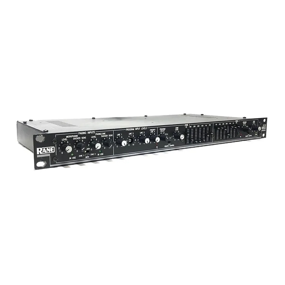
COMMERCIAL PROCESSOR
CP 62
Manual-1
Advertisement
Table of Contents

Subscribe to Our Youtube Channel
Related Manuals for Rane CP 62


Summary of Contents for Rane CP 62
-
Page 1: Quick Start
OUTPUTS to the amplifier inputs. Hook up a CD or tuner to PROGRAM INPUT 1 using a standard stereo RCA cable. Plug the RS 2 power supply into the red power connector on the back of the CP 62 and its line cord into the AC line—the PWR LED should come on. -
Page 2: Front Panel Description
EQ. 13. ZONE 2 mono graphic equalizer: Adjusts the frequency contour for the mono zone 2 output (±12 dB). 14. POWER indicator: Illuminates a warm yellow glow when the CP 62 is connected to an appropriate power source. Manual-2... -
Page 3: Rear Panel Description
Always turn your amplifier down before switching your grounds. 17. POWER input connector: This product requires a Rane RS 2 power supply. This is not a telephone jack! This calls for an 18-24 VAC center-tapped transformer. Consult the factory for replacement or substitution. - Page 4 OUTPUT provides a stereo zone. The ZONE 1 MODE switch can convert this to dual mono or stereo. nect any power to the CP 62, remove the top cover, and refer When in MONO, it is possible to use zone 1 as two mono to the assembly diagram in this manual.
- Page 5 CP 62: set the rear panel PAGING INPUTS ASSIGN switch to PHONE to control the PHONE/LINE signal from the front panel of the CP 62, or to MIC to control the MIC signal from the front panel.
- Page 6 R2 remotes connected to Zone 1. Plug a cable from the MAIN jack of the first R2 into the ZONE 1 REMOTE jack on the back of the CP 62 and set the first R2s slide switch to DUAL MONO, as shown in Figure 1b. Plug a cable from the MAIN jack of the second R2 into the AUX jack on the first R2.
-
Page 7: Preparing The Cables
4-conductor connector, named by an RJ number to describe it (i.e. RJ11, RJ14). This type of connector will not fit into the CP 62 remote outlets. The appropriate connector for the CP 62 is a 4-position/4-conductor, and is referred to as a “tele- phone modular handset connector”. -
Page 8: Chassis Grounding
Do not depend on the painted rack screws and rails to ground the chassis. 3. The CP 62 does not ground the chassis through the line cord. Make sure that these units are grounded either to another chassis which is earth grounded, or directly to the grounding screw on an AC outlet cover by means of a wire connected to a screw on the chassis with a star washer to guarantee proper contact.
Need help?
Do you have a question about the CP 62 and is the answer not in the manual?
Questions and answers