Table of Contents
Advertisement
Quick Links
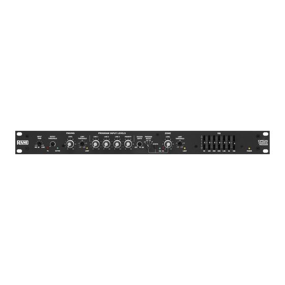
INPUT
DETECT
TRIM
THRESHOLD
+30
+60
MIC
LINE
OL
ACTIVE
Quick Start
If you were the type that cheated on school book reports by just
skimming through the reading assignments, then this section is
for you! It gives you not quite enough information to really know
what you're doing. But, if you follow the recommended set up
procedure, you should get at least a "B."
Keep the amplifiers and the CP 52S turned off until all con-
nections are made.
PAGE INPUT
Connect the PAGING INPUT to the Euroblock on the rear
panel. On the front, select the appropriate MIC or LINE switch
position. Then set the gain with the INPUT TRIM control,
then set the PAGING DETECT THRESHOLD and finally the
PAGING LEVEL. MIC PHANTOM POWER, HIGH/LOW
CUT FILTER and PAGE LEVEL TRACKS ZONE LEVEL
switches are located on the rear panel.
PROGRAM INPUTS
Connect line level program sources to the RCA PROGRAM
INPUT jacks (LINE L1, L2, L3 & PRIORITY). If you have a
priority program, like a jukebox, connect it to the PRIORITY
Input. The rear panel PRIORITY switch turns priority override
ON or OFF. The Priority program is automatically selected when
signal is detected at its Input. Set the rear panel PROGRAM
DETECT THRESHOLD and RELEASE TIME as desired.
WEAR PARTS: This product contains no wear parts.
OPERATORS MANUAL
PAGING
PROGRAM INPUT LEVELS
LEVEL
LIMIT
LINE 1
LINE 2
LINE 3
THRESHOLD
4
6
+8
4
6
4
6
4
–3
+16
2
8
2
8
2
8
2
–20
+20
0
10
0
10
0
10
0
LIMIT
ZONE
PRIORITY
DUCKER
PROGRAM
LEVEL
DEPTH
SELECT
6
4
6
L2 L3
4
L1
P
REMOTE
8
2
8
2
OFF
ON
10
0
10
0
10
SIG
OL
EXPAND OUTPUT
Wire the EXPAND OUTPUT Euroblock as required to a
mono feed delivering PAGE-only, PROGRAM-only or ZONE
(both) signal depending on the switch setting. This Output uses
a cross-coupled line driver and may be used balanced or unbal-
anced. Adjust the EXPAND OUTPUT LEVEL trim as desired.
ZONE OUTPUT
The ZONE OUTPUT uses a cross-coupled line driver and
may be used balanced or unbalanced. Set the front panel LIMIT
THRESHOLD as required. Depress the rear panel MONO
switch for a mono Zone.
ZR 1 REMOTE
You may use one ZR 1 Remote (sold separately) with the
CP 52S. Wire it to the ZONE REMOTE Euroblock as indi-
cated. If a ZR 1 remote is not used, any simple switch closure to
ground will work for the D0 and D1 pins. These pins are TTL
compatible (0 to 5 VDC). The logic is inverse Gray Code. Any
ground referenced 5 volt DC control may be used as the input to
Vc. Do not ground the Vr pin.
READ ME
The CP 52S is very versatile. While this makes a large num-
ber of system applications possible, it also results in complexity.
For this reason, it is important to use an organized approach for
setup and calibration. A highly recommended setup procedure
appears on page Manual-5. Please follow it to encounter fewer
problems and reduce the need to increase our collective phone
bills.
COMMERCIAL PROCESSOR
EQ
+
LIMIT
12
THRESHOLD
•
6
6
+8
•
0
–3
+16
•
8
6
•
–20
+20
12
LIMIT
40
100
250
630
CP 52S
CP 52S
COMMERCIAL
PROCESSOR
1.6k
4k
10k
POWER
Manual-1
Advertisement
Table of Contents

Related Manuals for Rane CP 52S


Summary of Contents for Rane CP 52S
-
Page 1: Quick Start
“B.” a cross-coupled line driver and may be used balanced or unbal- Keep the amplifiers and the CP 52S turned off until all con- anced. Adjust the EXPAND OUTPUT LEVEL trim as desired. - Page 2 Graphic Equalizer controls are “stereo,” with each slider controlling the response of both Left and Right channels. These controls allow ±12 dB adjustment of seven ISO center frequencies on 1 -octave centers. y POWER indicator illuminates when the CP 52S is connected to a proper power source. Manual-2...
- Page 3 8 7 6 1 PAGING INPUT Euroblock connector may be wired per instructions in CP 52S Audio Connections on page Manual-4. 2 MIC PHANTOM POWER switch, when ON, enables +15 volt Phantom Power to the PAGING INPUT connector. If the front panel LINE switch is selected, Phantom Power is defeated.
- Page 4 If a unit The silkscreened front panel metal is painted on both sides. is located far from the CP 52S or is of a type that might create This allows you to custom silk-screen the panel or add your own grounding problems, use isolation transformers.
- Page 5 Recommended Calibration Procedure The CP 52S is a very versatile instrument. While this allows it to conform to the requirements of a large number of system applica- tions, it also results in complexity. For this reason, it is very important to use an organized approach to system calibration. Once the system is connected and the internal switches set for your specific application, it is important to take the time for proper calibration.
- Page 6 To protect the setting of any rotary control, remove the knob and replace with one of the hole plugs included with the SCP 1S. To protect the entire front panel and allow use only with the ZR 1 Remote, use a Rane SC 1.7.
Need help?
Do you have a question about the CP 52S and is the answer not in the manual?
Questions and answers