Table of Contents
Advertisement
Advertisement
Table of Contents

Related Manuals for NCR NCR 5972


Summary of Contents for NCR NCR 5972
- Page 1 NCR 5972 2x20 Customer Display Release 2.0 Userʹs Guide BD20‐1372‐A Issue F ...
- Page 2 The product described in this book is a licensed product of NCR Corporation. NCR is a registered trademark of NCR Corporation. It is the policy of NCR Corporation (NCR) to improve products as new technology, components, software, and firmware become available. NCR, therefore, reserves the right to change specifications without prior notice. All features, functions, and operations described herein may not be marketed by NCR in all parts of the world. In some instances, photographs are of equipment prototypes. Therefore, before using this document, consult with your NCR representative or NCR office for information that is applicable and current. To maintain the quality of our publications, we need your comments on the accuracy, clarity, organization, and value of this book. Address correspondence to: Manager, Information Products NCR Corporation 2651 Satellite Blvd. Duluth, GA 30096 Copyright © 1999 By NCR Corporation Dayton, Ohio U.S.A. All Rights Reserved ...
- Page 3 Preface This manual is for hardware installer/service personnel, system integrators, field engineers, and programmers. Safety Requirements Warning: This device does not contain any user serviceable parts and should only be serviced by a qualified service technician. Caution: This device should only be powered by a (SELV) Safety Extra Low Voltage power supply source with an available power level of 5 amperes or less, and suitable for the country of installation. The power source must be certified by the appropriate safety agency for the country of installation. Le matériel doit être reliés electriquement au circuit å Très Basse Tension de Sécurité (TBTS) ayant une limite de 5 ampères correspondant de façon satisfaisante et acceptable dans le pays où le matériel doit être installé. Le source d’alimentation doit être approvée par une agence de normalisation appropriée et acceptable dans le pays où le matériel doit être installé. Caution: For continued protection against risk of fire, replace only with the same type and ratings of fuse. Pour prévenir et vous protéger contre un risque de feu, remplacer la ...
- Page 4 Chapter 1: Introduction ...
-
Page 5: Table Of Contents
Chapter 1: Introduction Table of Contents Chapter 1: Introduction Models ....................1‐1 Features ....................1‐1 VFD Models ..................1‐1 Hardware ..................1‐1 Software..................1‐2 LCD Models ..................1‐3 Hardware ..................1‐3 Software..................1‐3 Chapter 2: Site Preparation Physical Environment ................2‐1 Working Range ................2‐1 Storage Environment ..............2‐2 Transit Environment ..............2‐2 Dimensions.................. - Page 6 Chapter 1: Introduction Chapter 3: Installation Installing the Customer Display ............3‐1 SELV Power Source Warning ............3‐1 Installation Goal................3‐2 Cable Requirements ............... 3‐2 Power Supply Choices ..............3‐3 Installation Procedures ..............3‐3 NCR 5952/5962 Integrated Mount ........... 3‐3 RS‐232 Serial Interface ............... 3‐4 Diagnostics..................... 3‐5 Micro‐controller Test..............3‐5 External Memory Test Character (VFD Only)......3‐5 Pixel Test..................3‐6 Firmware Part Number Display........... 3‐6 Chapter 4: Programming Set Up Host/Retail Display Command Interface .......... 4‐1 Retail Display Commands ..............
- Page 7 Chapter 1: Introduction Enable Character Blink ..............4‐9 Disable Character Blink ............... 4‐10 Move Cursor Left................4‐10 Move Cursor Right............... 4‐10 Move Cursor Up ................4‐11 Move Cursor Down..............4‐11 Move Cursor To Specified Position ........... 4‐12 Brightness Adjustment ..............4‐13 Read Display ID Byte..............4‐13 Read Display ID String ..............4‐14 Display ESC Character..............4‐14 Select Character Set n..............4‐14 Character Sets ..................4‐15 Code Page 850 (International) ............ 4‐15 Code Page Katakana ..............4‐28 Code Page 866 (Cyrillic) ..............
- Page 8 Chapter 1: Introduction Revision Record Issue Date Remarks A Feb 97 First issue B Nov 98 Update to include 5972‐1100 C Mar 99 Added 5963 Integrated Display Mount D Jan 03 Removed 5972‐2x00 model. Added dimension information. E Feb 03 Added character sets. F June 03 Added new LCD models ...
- Page 9 Chapter 1: Introduction Radio Frequency Interference Statements Federal Communications Commission (FCC) Information to User This equipment has been tested and found to comply with the limits for a Class A digital device, pursuant to Part 15 of FCC Rules. These limits are designed to provide reasonable protection against harmful interference when the equipment is operated in a commercial environment. This equipment generates, uses, and can radiate radio frequency energy and, if not installed and used in accordance with the instruction manual, may cause harmful interference to radio communications. Operation of this equipment in a residential area is likely to cause interference in which case the user will be required to correct the interference at his own expense. NCR is not responsible for any radio or television interference caused by unauthorized modification of this equipment or the substitution or attachment of connecting cables and equipment other than those specified by NCR. The correction of interference caused by such unauthorized modification, substitution or attachment will be the responsibility of the user. The user is cautioned that changes or modifications not expressly approved by NCR may void the user’s authority to operate the equipment. Canadian Department of Communications This digital apparatus does not exceed the Class A limits for radio noise emissions from digital apparatus set out in the Radio Interference Regulations of the Canadian Department of Communications. Le présent appareil numérique n’émet pas de bruits radioélectriques dépassant les limites applicables aux appareils numériques de la classe A prescrites dans le Règlement sur le brouillage radioélectriques édicté par le ministrère des Communications du Canada. Voluntary Control Council For Interference (VCCI)
- Page 10 Chapter 1: Introduction ...
-
Page 11: Models
Introduction Chapter 1: Models The NCR 5972 Customer Display is designed to be an optional display device for the NCR retail terminals. It can also serve as a display for any industry‐standard PC. It is a Vacuum Fluorescent Display (VFD). • 5972‐1000 2x20 VFD (Light Gray) • 5972‐1100 2X20 VFD (Dark Gray, Low Post Mount) • 5972‐1200 2x20 VFD (Light Gray, Euro Symbol) • 5972‐1300 2x20 VFD (Dark Gray, Low Post Mount) • 5972‐1400 2x20 VFD (Charcoal Gray, Low Post Mount) • 5972‐2400 2x20 LCD (Light Gray, 1m Cable) • 5972‐2500 2x20 LCD (Light Gray, 4m Cable) Features VFD Models Hardware • Parallel I/F or EIA‐232 I/F support • The components for both interfaces are populated on one printed circuit board. Both interfaces are active, though only one interface can be physically connected at a time. The display communicates via the interface connected to it. • Socket for 32K of PROM for additional character sets • Cables ... -
Page 12: Software
Chapter 1: Introduction • Power Supply • Mounting Options Table Mount, Light Gray, 16‐in. Post Table Mount , Light Gray, 8‐in. Post Table Mount, Light Gray, No Post • Remote Mount, 8‐in. Post, Light Gray • Remote Mount, 8‐in. Post, Dark Gray • Integrated Mount , Telescoping Post, Charcoal Gray for 7458 • Integrated Mount, Telescoping Post, Light Gray for 5964 • Integrated Mount, Telescoping Post, Light Gray • No Mount Software • VFD control of 7x9 pixel characters • Parallel I/F • EIA‐232 Serial I/F (9600 BPS, 8 bit character, no parity, 1 stop bit) • Diagnostics • Support for 19 character sets • 3 Character sets in base unit • Code Page 858 (International) • Katakana • Code Page 866 (Cyrillic) ... -
Page 13: Lcd Models
Chapter 1: Introduction LCD Models Hardware • Cables • Power Supply • Mounting Options Table Mount, Light Gray, 16‐in. Post Table Mount, Light Gray, 8‐in. Post Table Mount, Light Gray, No Post • Remote Mount, 8‐in. Post, Light Gray • Integrated Mount, Telescoping Post, Light Gray for 5964 • Integrated Mount, Telescoping Post, Light Gray • No Mount Software • Powered RS‐232 I/F • Diagnostics • 1 Character set in base unit • Code Page 858 (International) ... - Page 14 Chapter 1: Introduction ...
-
Page 15: Chapter 2: Site Preparation
Site Preparation Chapter 2: This chapter describes the installation process including site considerations, operating conditions, mounting options, and connections. Physical Environment The working range, storage, and transit environments are presented in the following tables. Working Range Condition Range Temperature 10°C to 40°C (50°F to 104°F) Temperature Change 10°C (18°F) / Hour Humidity Range 20% to 80% (No Condensation) Humidity Change 10% / hour Barometric Pressure 105,000 Pa to 69000 Pa Note: Condensation may occur when equipment is transferred from cold to warm areas during shipment. The equipment design shall permit operation after condensation has occurred, a drying out process has been accomplished, and the equipment stabilized to the operating environment. ... -
Page 16: Storage Environment
Chapter 2: Site Preparation Storage Environment For periods up to three months: Condition Range Temperature ‐10°C to 50°C (14°F to 120°F Humidity 10% to 90% RH Barometric Pressure 105,000 to 70,000 Pa Transit Environment For periods up to one week: Condition Range Temperature ‐40° to 60°C (‐40°F to 140°F) Humidity 5% to 95% RH Barometric Pressure 105,000 to 70,000 Pa ... -
Page 17: Dimensions
Chapter 2: Site Preparation Dimensions VFD Models Desktop Mount 262 mm 30 mm (10.3 in.) (1.2 in.) 119 mm (4.7 in.) 162 mm (6.4 in.) 173 mm 178 mm (6.8 in.) (7.0 in.) 17241 ... - Page 18 Chapter 2: Site Preparation 16-Inch Post 30 mm 262 mm (1.2 in.) (10.3 in.) 119 mm (4.7 in.) 561 mm (22.1 in.) 95 mm 95 mm (3.75 in.) (3.75 in.) 15708 ...
- Page 19 Chapter 2: Site Preparation 8-Inch Post 262 mm 30 mm (10.3 in.) (1.2 in.) 356 mm 119 mm 356 mm (14.1 in.) (4.7 in.) (14.1 in.) 95 mm 95 mm (3.75 in.) (3.75 in.) 20131a ...
-
Page 20: Lcd Models
Chapter 2: Site Preparation LCD Models Desktop Mount 178 mm 30 mm (7.0 in.) (1.2 in.) 68 mm (2.6 in.) 139 mm (5.5 in.) 178 mm 173 mm (7.0 in.) 15412 (6.8 in.) ... -
Page 21: Electrical Environment
Chapter 2: Site Preparation Electrical Environment VFD AC Power Requirements • 120 VAC, 60 Hz (US, Canada, and others) via a wall mount power supply • 90‐264 VAC, 50‐60 Hz via a Universal Input power supply VFD DC Power Requirements • 10 VDC to 14VDC (0.8 A max. at 12VDC) LCD AC Power Requirements • No AC P/S available. The LCD receives power from the host via a powered RS‐232 connector. LCD DC Power Requirements • 10.6VDC to 13VDC (160mA max at 12VDC) Operational Environment System Configuration The VFD communicates with the host via the parallel port or EIA‐232 serial port of the host. Both interfaces are active at the same time. The ... -
Page 22: Mounting Hole Dimensions
Chapter 2: Site Preparation Mounting Hole Dimensions Mounting hole dimensions for routing cables from the Customer Display to a host terminal are explained as follows. 2x20 Customer Display Parallel Cable (VFD) Meters Corp. ID No. Feet Type Remote 497-0405676 13.1 1416-C278-0040 Integrated 497-0405677 1416-C278-0006 25-Pin D-Shell Plug 24-Pin Minifit Plug 8-Pin Microfit Plug 55 mm (2.25 in.) Dia. 32 mm (1.25 in.) Dia. - Page 23 Chapter 2: Site Preparation 2x20 Customer Display Serial Cable (LCD) Meters Feet Corp. ID No. Type Remote 497-0407636 13.1 1416-C278-0040 Integrated 497-0407637 1416-C278-0006 9-Pin D-Shell Receptacle 24-Pin Minifit Plug 8-Pin Microfit Plug 55 mm (2.25 in.) Dia. 32 mm (1.25 in.) Dia. 19 mm (0.75 in.) Dia.
- Page 24 2-10 Chapter 2: Site Preparation ...
-
Page 25: Chapter 3: Installation
Installation Chapter 3: Installing the Customer Display SELV Power Source Warning This device should only be powered by a (SELV) Safety Extra Low Voltage power supply source with an available power level of 5 amperes or less, and suitable for the country of installation. The power source must be certified by the appropriate safety agency for the country of installation. -
Page 26: Installation Goal
Chapter 3: Installation Caution: The power supply cord is used as the main disconnect device. Ensure that the socket outlet is located/installed near the equipment and is easily accessible. Le cordon d’alimentation est utilisé comme interrupteur général. La prise de courant doit etrê située ou installée a proximité du matériel et être facile d’accés. Installation Goal The goal for installing the NCR 5972 Customer Display is for a reasonably trained operator or store manager to fully install the terminal in less than 15 minutes. To qualify as reasonably trained an installer or store manager must be fluent with the terminology and basic technology of PC hardware and software. This level of knowledge can typically be found in an individual who has installed several PC systems, and who routinely uses a PC for personal or business computing. Cable Requirements Cable choices group: • Integrated Parallel Cable (0.6 m length cable) (VFD only) • Remote Parallel Cable (4.0 m length cable) (VFD only) • Integrated EIA‐232 Serial Cable (0.6 m length cable) (VFD only) • Remote EIA ‐232 Serial Cable (4.0 m length cable) (VFD only) • Integrated Powered EIA‐232 Cable (1.0m length cable) (VFD only) • Remote Powered EIA‐232 Serial Cable (4.0m length cable) (VFD only) • Integrated Powered EIA‐232 ... -
Page 27: Power Supply Choices
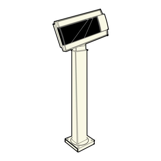
Chapter 3: Installation Power Supply Choices Power Supply Choices Group: • No Power Supply for 7452/7453 applications • Universal Input Power Supply Adapter; 90‐264 VAC, 50‐60 Hz; (VFD only) Installation Procedures Not all models are supported for every NCR retail terminal. For specific installation instructions see the appropriate retail terminal Hardware User’s Guide. NCR 5952/5962 Integrated Mount Touch Screen 2 x 20 Customer Display (Post-Mounted) 12682 See the NCR 5952 Wedge DynaKey User’s Guide (BD20‐1370‐A), or NCR 5962 Wedge Touch Screen User’s Guide (BD20‐1371‐B) for procedures how to install the integrated mount. ... -
Page 28: Rs-232 Serial Interface
Chapter 3: Installation RS-232 Serial Interface You can connect the Customer Display to one of the host terminal 9‐pin serial connector. Configure the terminal serial port as follows: • 9600 baud • 8 data bits • 1 start bit • No parity • 1 stop bit • Half‐Duplex ... -
Page 29: Diagnostics
Chapter 3: Installation Diagnostics The 5972 Customer Display has internal Power Up Diagnostics that occur soon after power‐up or if a Reset Display command is received from the host software. When the hardware is powered down, all registers and memory are lost. No recovery is possible. The Power Up Diagnostics include the following tests: • Micro‐controller test • External character PROM test (VFD only) • Pixel Number Display Micro-controller Test For serial communications, the CTS line is set in a Marking condition (negative voltage) at the start of the test. For VFD parallel communications, the Busy line is set active at the start of the test. The first test is the Micro‐controller test which checks operation at the Micro‐controller. If an error is discovered, testing halts, and the firmware begins executing a forever do nothing loop. No response is sent to the host. If the Micro‐controller Test passes, the CTS and Busy line exception conditions are lifted. External Memory Test Character (VFD Only) A separate test is performed on the external character PROM, if it exists. The PROM status is noted and saved for terminal retrieval later using the Reset command. If an error is discovered, all character sets stored in the PROM are considered invalid, and any command received attempting to switch to one of these character sets is treated as an invalid command and ignored. ... -
Page 30: Pixel Test
Chapter 3: Installation Pixel Test All Pixels are turned on for two seconds. The unit does not have the capability to determine if it passes this pixel test. You must visually examine the display for any pixel failure. Firmware Part Number Display The current firmware part number of the unit is displayed for two seconds. ... -
Page 31: Chapter 4: Programming Set Up
Programming Set Up Chapter 4: Firmware and software function descriptions for the NCR 5972 Retail Display are presented in this chapter. Host/Retail Display Command Interface The Retail Display accepts two types of data: display data and command data. If a byte received from the host is any character except the ESC (0x1B) character, it is processed as a character and displayed on the Retail Display. If an ESC character (0x1B) is received, the subsequent byte(s) is processed as a command. If the subsequent byte is an invalid command it is ignored. If an ESC is received, but no command byte is received immediately, the firmware waits forever if need be and uses the next received byte(s) to complete the command. Note: Each command consists of at least two bytes. The first byte (0x1B) is a command identifier indicating the next byte(s) is a command byte. The command byte may be followed by parameter or data bytes depending on the command. Also note that the ESC character can be displayed by using the Display ESC Character command. ... -
Page 32: Retail Display Commands
Chapter 4: Programming Set Up Retail Display Commands The following table describes the Retail Display commands supported: Command Function 1B 01 Reset Display 1B 02 Erase Display 1B 04 Set Diagnostic State On 1B 05 Set Display State On 1B 06 Set Low Power State On (Default) 1B 07 Enable Cursor 1B 08 Disable Cursor (Default) 1B 09 Set Screen Save Blank 1B 0A Set Screen Save Walk (Default) 1B 0B Turn On Screen Save 1B 0C Disable Screen Save Feature 1B 0D Enable Character Blink 1B 0E Disable Character Blink (Default) 1B 0F Move Cursor Left 1B 10 Move Cursor Right ... - Page 33 Chapter 4: Programming Set Up Command Function 1B 1B Display ESC Character 1B 20 Select Character Set 1 (Default) 1B 21 Select Character Set 2 1B 22 Select Character Set 3 1B 23 Select Character Set 4 (External ROM required) 1B 24 Select Character Set 5 (External ROM required) 1B 25 Select Character Set 6 (External ROM required) 1B 26 Select Character Set 7 (External ROM required) 1B 27 Select Character Set 8 (External ROM required) 1B 28 Select Character Set 9 (External ROM required) 1B 29 Select Character Set 10 (External ROM required) 1B 2A Select Character Set 11 (External ROM required) ...
-
Page 34: Reset Display
Chapter 4: Programming Set Up Reset Display Format: 1B 01 Returns: xx yy zz • where xx is the Microcontroller status: − 00 = OK If a failure occurs, testing halts, and the firmware begins executing a loop as described in the Internal Power UP Diagnostics section in the Installation chapter. • where yy is the External Character PROM status: − 00 = Not present (Always 00 for LCD) − 01 = OK, present − FF = Failure •... -
Page 35: Erase Display
Chapter 4: Programming Set Up Erase Display Format: 1B 02 Description: This command clears all of the displayed characters by writing a space to each display position. A space is defined as character 0x20 of the current character set. The cursor moves to the 0 position. Set Diagnostic State On Format: 1B 04 Description: This state is exclusive from the On and Low Power States. This command causes the firmware to display the current firmware part number of the device for five seconds, and then step through each installed 256‐character set (default and user‐defined) displaying one character at a time on all 40 display positions at a rate of about one character per second. The firmware starts with the currently selected character set, and then displays all of the characters from the other sets the same way. This continues until one of the other state commands is performed. Prior display data is saved and can be restored before sending the Set Display State On. Note: The LCD only has one character set. ... -
Page 36: Set Display State On
Chapter 4: Programming Set Up Set Display State On Format: 1B 05 Description: This state is used for normal run‐time conditions. This operation instructs the firmware to leave one of the other states and begin performing normal refresh operations. There may be a slight delay before the Vacuum Fluorescent Display (VFD) reaches the specified brightness setting when exiting the Low Power State. This delay should not exceed 1 second from the time the command is received until the time the VFD reaches the specified brightness. The Screen Save feature may be in force during the Display On state. This means that after about five minutes of no new display activity, the Screen Save feature could take over and cause the display to go blank or begin walking from right to left. Set Low Power State On Format: 1B 06 Description: This state is used to reduce Retail Display power consumption and extend the life of the Retail Display VFD. Power is removed from the display, but the Retail Display controller is still fully operational and continues to accept commands. This command causes the firmware to blank or turn off the Retail Display. Display data can be processed while the display is in the Low Power State, but it does not appear until the Low Power State ... -
Page 37: Enable Cursor
Chapter 4: Programming Set Up Enable Cursor Format: 1B 07 Description: This command causes a flashing cursor to be used whenever the Display On state is in force. When the cursor is enabled, the cursor is visible and flashing at the current cursor position. The flashing cursor should be visible for 1 second and then the character at the cursor position should be visible for 1 second. The effect is to alternate between the character and the cursor. The cursor is defined as character 0X5F of whatever character set is currently chosen. For the three supported character sets, the cursor is the bottom row of pixels turned on. For a user‐ defined character set, the cursor is whatever is defined as character 0X5F of the character set. When the cursor is enabled, it overwrites the character at the cursor position. If the cursor is disabled, the character at the cursor position is left visible. Note: The cursor on the LCD blinks on and off every .5 second. The cursor displays concurrently with whatever character may already be displayed at the cursor position. Disable Cursor Format: 1B 08 Description: This command causes the cursor to be turned off. This is the default state for the cursor after power‐up. ... -
Page 38: Set Screen Save Blank
Chapter 4: Programming Set Up Set Screen Save Blank Format: 1B 09 Description: This command is intended to preserve the life of the display hardware unit. The firmware maintains a five‐minute timer that triggers this feature. The Screen Save feature can be disabled through a command from the host software. When the feature is not disabled, two specific options exist. The Set Screen Save Blank operation causes the display to go blank when the timer expires. When the firmware receives the command code, the Screen Save mode is canceled, and the five‐minute timer is established. Screen Save Blank removes power from the Retail Display, and refreshes the display in the same manner as the Set Low Power On command. At power up, the timer is established at five minutes, and Screen Save Blank is established as a default. The five minute timer is not reset by any invalid or incorrect command. Set Screen Save Walk Format: 1B 0A Description: This command causes the visible display to walk right to left when the Screen Save timer expires (five minutes). The characters on the display appear to walk across the corresponding display row from right to left. The two lines in the 2x20 Display walk in parallel completely off the left side of the display, and then the two lines appear to come back from the right. If the display is space filled, then no effect is perceived even though the walking is ... -
Page 39: Turn On Screen Save
Chapter 4: Programming Set Up Turn On Screen Save Format: 1B 0B Description: This command causes one of the screen save functions (Set Screen Save Blank or Set Screen Save Walk) to activate immediately rather than waiting for the screen save timer to expire. If the Disable Screen Save command is in effect when this command is issued, it is canceled, and the screen saver is enabled and activated immediately. Disable Screen Save Option Format: 1B 0C Description: The firmware ceases to keep time for the screen save activity from the host software, and the display neither goes blank nor begins to walk due to inactivity from the host. This command can be canceled by the Turn On Screen Save, Set Screen Save Blank, and Set Screen Save Walk commands. Enable Character Blink Format: 1B 0D Description: The blink attribute is the only modifier which is supported for the display character positions. Each time a new ... -
Page 40: Disable Character Blink
4-10 Chapter 4: Programming Set Up Disable Character Blink Format: 1B 0E Description: This command counteracts the Enable Character Blink. The firmware implements all new character codes with an on and holding character presentation. On power up, the character blink modifier is defaulted to disabled. Move Cursor Left Format: 1B 0F Description: Moves the cursor one position to the left. When the cursor is at the left end of the upper line, it moves to the right end of the lower line. When the cursor is at the left end of the lower line, it moves to the right end of the upper line. The cursor location always indicates the position of the next character to be displayed, whether the cursor is enabled and blinking or not. After each character is displayed, the firmware performs a logical Move Cursor Right command. Move Cursor Right Format: 1B 10 Description: Moves the cursor one position to the right. When the cursor is at the right end of the upper line, it moves to the left end ... -
Page 41: Move Cursor Up
Chapter 4: Programming Set Up 4-11 Move Cursor Up Format: 1B 11 Description: Moves the cursor up one line. When the cursor is on the upper line, the cursor is moved to the same column on the lower line. The cursor location always indicates the position of the next character to be displayed, whether the cursor is enabled and blinking or not. After each character is displayed, the firmware performs a logical Move Cursor Right command. Move Cursor Down Format: 1B 12 Description: Moves the cursor down one line. When the cursor is on the lower line, the cursor is moved to the same column on the upper line. The cursor location always indicates the position of the next character to be displayed, whether the cursor is enabled and blinking or not. After each character is displayed, the firmware performs a logical Move Cursor Right command. ... -
Page 42: Move Cursor To Specified Position
4-12 Chapter 4: Programming Set Up Move Cursor To Specified Position Format: 1B 13 nn Range: 00 ≤ nn ≤ 27 (hex) Description: Moves the cursor to the specified position. Position 0 is the upper leftmost position, and position 27 is the lower rightmost position. Any value outside this range is discarded, the command is ignored, and the cursor is moved. The cursor location always indicates the position of the next character to be displayed, whether the cursor is enabled and blinking or not. After each character is displayed, the firmware performs a logical Move Cursor Right command. The character positions are shown in the following: 0C 0D 0E 0F 10 11 12 13 0A 0B 14 15 16 17 18 19 1A 1B 1C 1D 1E 1F 20 21 22 24 25 26 27... -
Page 43: Brightness Adjustment
Chapter 4: Programming Set Up 4-13 Brightness Adjustment Format: 1B 17 nn Range: 01 ≤ nn ≤ 05 Description: Adjusts the brightness of the entire display. Individual characters or display positions are not adjusted. On power up, the default brightness setting is 5 (100%). Brightness 01 02 03 04 05 100% Note: This command is not supported by the LCD. The only action taken is to take the display out of Screen Save. Read Display ID Byte Format: 1B 18 Returns: 0x8A Description: This command is a request for the Retail Display to return an identifier. The Retail Display returns one byte (0x8A) that identifies the Retail Display as a 2x20 with 7x9 dot matrix. ... -
Page 44: Read Display Id String
4-14 Chapter 4: Programming Set Up Read Display ID String Format: 1B 19 Returns: 0x1A, “NCR 5972, XXX-XXXXXXX” Description: where 0x1A is a 1 byte string length indicator which indicates the length of the string that follows the string length indicator. For example, 1AH characters are sent after the string length indicator. Note: indicates a space character (20H). The quotation marks “” are not part of the string and are not returned. XXX‐XXXXXXX represents the current firmware part number. Description: This command is a request for the Retail Display to return an ASCII string with detailed product information. Display ESC Character Format: 1B 1B Description: This command is a request for the ESC character to be displayed at the current cursor position. Select Character Set n Format: 1B20 - 1B32 ... -
Page 45: Character Sets
Chapter 4: Programming Set Up 4-15 Character Sets There are three character sets pre‐installed. • Code 858 (International) (VFD and LCD) • Katakana (VFD only) • Code 866 (Cyrillic) (VFD only) The VFD supports 16 additional character sets of 256 characters each. These additional character sets are inside a PROM that plugs into a socket on the PCB. All of the characters sets are stored in non‐volatile memory. Code Page 850 (International) ........●●●..●...●●●●●. .●●●●●....●●●..●●●.. ●..● ●●●●●●● ..●●.●●. - Page 46 4-16 Chapter 4: Programming Set Up ..........●..●..● ●..●●●●● ..● ...●..●.●.. .●●●●●● ●●●..●..●..● ..●...● .●.●.●..●●● ..●●●..●.●.. ●●●●●.. ●..●..● ..●●●●● ..●.●..●●●●● .●●●●●. ..●.●.. ●●...●● ●●●●●●● ●●●●●●● ..●...● ...●..●.●.. .●●●..●...
- Page 47 Chapter 4: Programming Set Up 4-17 ......●●....●●..● ..●.●..●..●●●..●..●..●..●●...●. ..●.●.. .●●●●●. .●...●. ..●..●..●... ●●●●●●● ●..●..●..●.●...●..●..●.●.. .●●●●●..●..●.●....●..●..
- Page 48 4-18 Chapter 4: Programming Set Up ..........●●●●●. .●●●●●....●.....●... ●..● ●..● ..●●..●●..●....●.. ●..● ●..● ●●●●●●● ..●●..●●..●..●. ●..●●●●●. .●●●●●● ......●...
- Page 49 Chapter 4: Programming Set Up 4-19 ..........●..● ●..● ●●●●●●. ●●●●●●. .●●●●●. .●●●●●. .●●●●●. ●.●.●.● ●●..● ●..● ●..● ●..● ●..● ●..● ●..●..● ●.●...● ●..● ●..● ●..● ●..● ●..●..●..● ●..●..● ●..● ●●●●●●. ●..● ●●●●●●. .●●●●●.
- Page 50 4-20 Chapter 4: Programming Set Up ..........●..●....● ..●●●..●..●....● ..●...● ..●●●●●●. ●●●●●●. .●●●●●● .●●●●●● .●●●●●. ..●..●●●●●● ●..● ●..●..● ●..● ●..● ●..● .●●●●..
- Page 51 Chapter 4: Programming Set Up 4-21 .................●..●..●........●..●..●... ●..● ●..● ●..● ●●●●●●● ...●..●..●... ●..●..● ●..● .●...●..●. .●●....●●.
- Page 52 4-22 Chapter 4: Programming Set Up ...●..●..●...●..●..●....●.●..●....●...●●●●●● ●●●●●●● ●..●....●●●●●. .●●●●●..●..● ●..● ●..●..●..●..●..●●●●●. ●..● ●..● ●●●●●.. ●●●●●●..●..●..●..●...
- Page 53 Chapter 4: Programming Set Up 4-23 ..●..●..●..●●..● ..●●..● ..●●●..●●●..●..●..●..●..●●. .●..●●. .●...●. .●...●. ●..● ......●...●. .●...●. ●..●. ●.●●●●. ●●..● ...●..●●●●●. ..●●●.● ..●●●.. ●..● ●..●. ●.●...● ...●..●..● ....
- Page 54 4-24 Chapter 4: Programming Set Up ...●..●..●●●●●. ..●.●..●.●...●.●.. ●..●..● ..●.●..●..●.●..●.●...●.●.. ●.●.●.● .●●●●●. .●●●●●. ..●.●..●.●...●.●.. ●..● ●..● ●.●...● ●●●.●.. ●●●●●.. ●●●.●..●.●.. ●..● ●..● ●.●.●.● ..●..●.●..●..●..
- Page 55 Chapter 4: Programming Set Up 4-25 ..●.●...●.●....●●●..●..● ●●●●●...●.●...●.●..●... ●●●●●●● ●●●●●●● ●●●.●●● ..●.●●● .●●●●●..●.. .●...●..●....●...●. .●●●●●. .●..● ●●●.●●● ●●●●●●● ●●●.●●● ●..●. ●●●●..● ..●.●●● .●...●.
- Page 56 4-26 Chapter 4: Programming Set Up ..●....●..●..●●..● ..●●..● ..●..●●●●..●.●..●..●..●●. .●..●●..●..●. .●●●●●. .●●●●●. .●●●●●..●●●●●..●..● ●..●. ●..● ●..● ●..● .●●●●●. .●..● ●..● ●●●●●●. ●..● ●..● ●..● ●..● .●..●...
- Page 57 Chapter 4: Programming Set Up 4-27 ......●...●....●●●●●..●....●●●....●... ●.....●...●....●●... ●●●●●●● .●●●●..●...●...●..●... ●..●....●●●....●...
- Page 58 4-28 Chapter 4: Programming Set Up Code Page Katakana ........●●●..●...●●●●●. .●●●●●....●●●..●●●.. ●..● ●●●●●●● ..●●.●●..●..●●●.. .●●●●●. ●.●.●.● ●●.●.●● ●●●●●●● ●●.●.●● ●●●●●●● ..●●●.. ●..● ●●●●●●● ●●●●●●● ●●●●●●●...
- Page 59 Chapter 4: Programming Set Up 4-29 ....●....... .●●●●●..●●●..●..●....●....●●●●●. ..●●●..●..●..●..●●●●....●..●●●●●..●..●●. .●●..●..●. ●●●●●●● ●●●●●●● ●●●●●●● ...●..●..●...
- Page 60 4-30 Chapter 4: Programming Set Up ................... .●●●●●. ●..● .●...●..●......●. ●●●●●●● ●..● ..●.●..●.....●.. ●●●●●●● ●●●●●●● ●..● ......●...
- Page 61 Chapter 4: Programming Set Up 4-31 ..........●●●●●●. ●●●●●.. ●●●●●●● ..●●●.. .●●●●●. ..●●●.. .●●●●●. ●..● ●..● ●..● ●..●. ●..●...●. .●...●. ●..●●.● ●..● ●..● ●..●..● ●..●.. ●.●.●.● ●..● ●●●●●●. ●..●..● ●●●●●..●...
- Page 62 4-32 Chapter 4: Programming Set Up ..........●●●●●●● ●..● ●..● ●..● ●..● ●..● ●●●●●●● ●..● ●..● ●..● ●..● ...●..●...●..●. ●..● ●..● ●..● ...●..●.●.. .●...●..●.. ●..● ●..● ●..●..● ...●..●..●.●..●...
- Page 63 Chapter 4: Programming Set Up 4-33 ............●..●. .●..●........●..●......●●●.●●. ●.●●●●..●..●. .●...●..●..●●●●●. ●..●..● ●..● ...●..●. .●..●..●..●..●...
- Page 64 4-34 Chapter 4: Programming Set Up .●●●..● .......... ●..●●●..●..........●...●........●..● ..●●●..●..●●●.. .●●●●●..●.. ●..● ..●...●. ..●●..●...●..●..●●..
- Page 65 Chapter 4: Programming Set Up 4-35 ..................................................
- Page 66 4-36 Chapter 4: Programming Set Up ...............................●..●....●..●....●..●●●●●. .●●●●●. .●●●●●. .●●●●●● ..●●●..●●●●.
- Page 67 Chapter 4: Programming Set Up 4-37 ..●....●......●●●●●●. ●..● ●..●..● ..●..●●●● ..●. .●●●●●. ●●●●●●● ●..● ●..●..● ..●. ..●...● .●●●●..●..●..● ●●●●●●● ..●..●...● .●..● .●.●..● ...●... ●●●●●●● ...●..●..●..● ..●.● ..● ..●..
- Page 68 4-38 Chapter 4: Programming Set Up ..● ..●......●..● .●●●●●. ..●..●●●●.. .●●●●●● ..●●●.. .●...●. ..●..●. ..●..●..●..● ..●...●. ●●●●●●● ●●●●●●● ●●●●●●● ...●.●..●..● .●...●..●..●..●...● ..●.. .●●●●●● ..● .●...●.
- Page 69 Chapter 4: Programming Set Up 4-39 ..................................................
- Page 70 4-40 Chapter 4: Programming Set Up ●.●.●.● ●..●.●.●. .●.●.●. ●.●.●.● ●..●.●.●. .●.●.●. ●.●.●.● ●..●..●.●.●. .●.●.●. ●.●.●.● ●.●..●.●.●. .●.●.●. ●.●.●.● ●●..●.●.●. .●.●.●. ●.●.●.● ●.●..●.●.●. .●.●.●. ●.●.●.● ●..●..●.●.●. .●.●.●. ●.●.●.● .●.●.●. .●.●.●..●.●.●.● .●.●.●. .●.●.●.
-
Page 71: Code Page 866 (Cyrillic)
Chapter 4: Programming Set Up 4-41 Code Page 866 (Cyrillic) ........●●●..●...●●●●●. .●●●●●....●●●..●●●.. ●..● ●●●●●●● ..●●.●●..●..●●●.. .●●●●●. ●.●.●.● ●●.●.●● ●●●●●●● ●●.●.●● ●●●●●●● ..●●●.. ●..● ●●●●●●● ●●●●●●●... - Page 72 4-42 Chapter 4: Programming Set Up ....●....... .●●●●●..●●●..●..●....●....●●●●●. ..●●●..●..●..●..●●●●....●..●●●●●..●..●●. .●●..●..●. ●●●●●●● ●●●●●●● ●●●●●●● ...●..●..●...
- Page 73 Chapter 4: Programming Set Up 4-43 ................... .●●●●●. ●..● .●...●..●......●. ●●●●●●● ●..● ..●.●..●.....●.. ●●●●●●● ●●●●●●● ●..● ......●...
- Page 74 4-44 Chapter 4: Programming Set Up ..........●●●●●●. ●●●●●.. ●●●●●●● ..●●●.. .●●●●●. ..●●●.. .●●●●●. ●..● ●..● ●..● ●..●. ●..●...●. .●...●. ●..●●.● ●..● ●..● ●..●..● ●..●.. ●.●.●.● ●..● ●●●●●●. ●..●..● ●●●●●..●...
- Page 75 Chapter 4: Programming Set Up 4-45 ..........●●●●●●● ●..● ●..● ●..● ●..● ●..● ●●●●●●● ●..● ●..● ●..● ●..● ...●..●...●..●. ●..● ●..● ●..● ...●..●.●.. .●...●..●.. ●..● ●..● ●..●..● ...●..●..●.●..●...
- Page 76 4-46 Chapter 4: Programming Set Up ............●..●. .●..●........●..●......●●●.●●. ●.●●●●..●..●. .●...●..●..●●●●●. ●..●..● ●..● ...●..●. .●..●..●..●..●...
- Page 77 Chapter 4: Programming Set Up 4-47 .●●●..● ........●●●. ●..●●●. ●●●●●●● ●●●●●●. ●●●●●●● ...●..●●●..●..●..●...●. .●...●. .●..● .●..● .●..● .●...●. ●..● ●..● ..●..●..● .●..●...●. ●..● ●..● ..●●●●●. .●●●●●. .●..●...●.
- Page 78 4-48 Chapter 4: Programming Set Up ●..●........... ●..● ●..● ●..●. ●..● ●..●..● ●..●..● .●●●●●. ●..● ●..●..● ●..●. ●..● ●..●..● ●..●..● .●...●. ●..● ●..●..● ●..●. ●..● ●..●..● ●..●..● ..●.●.. ●..●..● ●..●. ●..●..● ●..●..● .●●●●●● ...●..●●●●●●...
- Page 79 Chapter 4: Programming Set Up 4-49 ............●..●..........●●........●..●. ●..●. ●●...●● ●..● ●..● ..●●●●● .●●●●●. ●...●●. ●...●●. ●●...●● ●..● ●..● .●..●.. .●..●...
- Page 80 4-50 Chapter 4: Programming Set Up ..●.●..●.....●..●.....●..●.●..●.....●..●.....●... ●●●●..●.●....●..●.....●..●.●..●.....●..●.....●... ●●●●●.. ●●●●... ●●●●... ●●●●●●● ●●●●●●● ...●●●● ...●●●●...
- Page 81 Chapter 4: Programming Set Up 4-51 ..●.●..●....●.●..●....●.●..●....●.●..●... ●●●●●●● ..●.●..●●●● ...●●●● ..●.●...●.●..●..●....●.●..●... ●●●●●●● ●●●●●●● ●●●●●●● ..●●●●● ...●●●● ...●●●● ..●●●●●...
- Page 82 4-52 Chapter 4: Programming Set Up ..............................●..● ●..●..● ●..●..● ●●●..●..● ●●●..●●●●●. ●..● ●..●..● ●..●..● ●.●..●..● ●..● .●..
- Page 83 Chapter 4: Programming Set Up 4-53 ......●..●... ●..● ....●..●.●. .●●●●●. .●●●●..●●.●●.● .●...●. .●●●●..●.●●.●. .●...●. .●●●●..●..●●●● .●●●●●. .●●●●..●..●... ●..● ....●..●..........
- Page 84 4-54 Chapter 4: Programming Set Up ...
-
Page 85: Chapter 5: Service
Service Chapter 5: Safety Requirements Carefully follow these safety requirements before servicing the Retail Display: Warning: This device does not contain any user serviceable parts and should only be serviced by a qualified service technician. Caution: Before servicing the display, disconnect the AC power cord from the retail terminal or PC to which the display is connected. Also disconnect the cables from the PC/terminal to the display. Caution: For continued protection against risk of fire, replace only with the same type and ratings of fuse. The fuse is designated F1 in the Vacuum Fluorescent Display. Pour prévenir et vous protéger contre un risque de feu, remplacer la fusible avec une autre fusible de même type, seulement. Caution: The power supply cord is used as the main disconnect device. Ensure that the socket outlet is located/installed near the equipment and is easily accessible. ... - Page 86 Chapter 5: Service Caution: This device should only be powered by a (SELV) Safety Extra Low Voltage power supply source with an available power level of 5 amperes or less, and suitable for the country of installation. The power source must be certified by the appropriate safety agency for the country of installation. Le matériel doit être reliés electriquement au circuit å Très Basse Tension de Sécurité (TBTS) ayant une limite de 5 ampères correspondant de façon satisfaisante et acceptable dans le pays où le matériel doit être installé. Le source d’alimentation doit être approvée par une agence de normalisation appropriée et acceptable dans le pays où le matériel doit être installe. ...
-
Page 87: Servicing The Display
Servicing the Display Warning: Before servicing the equipment plug your safety strap into a proper grounding outlet. Failure to do so could damage the equipment. Normal Operation On power‐up, the unit displays the firmware part number for 2 seconds, then lights all pixels for 2 seconds, then goes blank and awaits commands from the host. Troubleshooting Procedures The NCR 5972 Customer Display requires minimal maintenance. Should the display malfunction, adhere to the procedures in the following troubleshooting chart. Symptom Probable Cause Solution Blank screen on No power to unit ... -
Page 88: Servicing The Vfd Or Lcd
Chapter 5: Service Servicing the VFD or LCD If the unit still does not perform properly, you need to replace the display. Before disassembly, verify if your model has the labeling and serial numbers indicated on the rear of the cover of the display or on the bottom of the cabinet. This cover must be retained when replacing the display. Do not replace this cabinet with a non‐serialized cover. Caution: Be careful not to damage screw holes or cables when replacing the display. If you are replacing the display having a serialized cover proceed as follows: ... - Page 89 Chapter 5: Service 1. Remove only two cabinet screws. (2) Bracket Screws 14540 (2) Cabinet Screws 14540 2. Remove the PC board. 3. Disconnect the board from the 24‐position connector. 4. Reinstall a new PC board. 5. Route the cable. VFD: Pull the cable down so the strain relief becomes flush with the housing. LCD: Route the cable through the strain relief guides located in the cabinet. ...
-
Page 90: Cleaning The Display
Chapter 5: Service 6. Replace the cover and secure it with cabinet screws (2). 7. Reassemble the faulty board and mail it to NCR Customer Services for repair. Note: If you are replacing a non‐serialized unit, you may remove all screws (4) or disassemble the display in whatever method is easiest for you. Cleaning the Display Remove power from the unit before cleaning. When cleaning is required, a soft cloth dipped in a mild detergent can be used to clean the cabinet. Only a damp cloth is required so that no moisture can enter the cabinet. Never spray the cleaner directly onto the unit. Care should be taken not to scratch the lens during cleaning. Note: No preventive maintenance is required to meet the Service Calls per Machine per Year requirement. ...
Need help?
Do you have a question about the NCR 5972 and is the answer not in the manual?
Questions and answers