
Subscribe to Our Youtube Channel
Related Manuals for NCR 5966


Summary of Contents for NCR 5966
-
Page 1: User Guide
NCR RealPOS Value Touch Display (5966 15-Inch) Release 1.0 User Guide B005-0000-1770 Issue D... - Page 2 NCR, therefore, reserves the right to change specifications without prior notice. All features, functions, and operations described herein may not be marketed by NCR in all parts of the world. In some instances, photographs are of equipment prototypes. Therefore, before using this document, consult with your NCR representative or NCR office for information that is applicable and current.
-
Page 3: Table Of Contents
Humidity ................... 2-2 Weight ..................... 2-2 Dimensions....................2-3 5966 with Table Top Mount ............. 2-3 5966 with 5964-K032 Table Top Mount .......... 2-3 System Cables ..................2-4 VGA Cable ..................2-4 12.1-Inch LCD Aux Power Cable............. 2-4 Power Cords..................2-4 Chapter 3: Hardware Installation Installing the 5966 ................... - Page 4 Navigate Up................3-10 Navigate Down................3-10 Power Button ................3-10 Screen Adjustment Operation Procedure........3-11 Chapter 4: OSD Adjustment Main Menu ....................4-1 OSD Adjusting and Controls..............4-2 Chapter 5: Touch Screen Calibration - Windows Installing and Calibrating the Touch Screen ........... 5-1 Installing the Driver and Utility............
-
Page 5: Revision Record
Audience This book is written for hardware installer/service personnel, system integrators, and field engineers. Note: This document is NCR proprietary information and is not to be disclosed or reproduced without consent. Safety Requirements The NCR RealPOS 5966 conforms to all applicable legal requirements. To view the compliance statements see the NCR RealPOS Peripherals Safety and Regulatory Statements (B005-0000-1701). -
Page 7: Chapter 1: Overview
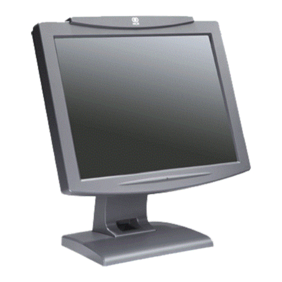
The NCR 5966 is a 15-inch low cost XGA (1024x768) Liquid Crystal Display with a 5-wire resistive touch screen for operator input. -
Page 8: Product Components
Chapter 1: Overview Product Components The 5966 is shipped with a Standard Table Top Mount. This mount can be replaced with an NCR 5964-K030 (Beige) or NCR 5964-K031 (Charcoal) Table Top Mount if desired. Note: When using the alternate mount the Vesa Adapter Plate is required (included with the unit). -
Page 9: Chapter 2: Site Preparation
Store AC Wiring Requirements The customer must provide suitable AC power for the monitor. A dedicated unswitched power line dedicated to the NCR equipment installation is recommended. Refer to the NCR Workstation and Peripherals AC Wiring Guide (BSTO-2115-53) for store AC wiring requirements. -
Page 10: Environmental Requirements
Chapter 2: Site Preparation Environmental Requirements Barometric Pressure The terminal operates within the following barometric pressure conditions: • Maximum operating altitude: 2,750 m (9,843 ft.) • Operating range of pressure: 105 to 72.4 kPa (15.2 to 10.5 lb./in.) Temperature The terminal operates over the temperature ranges shown below. Continuous operation must be avoided at or near the indicated temperature extremes or in locations where the temperature changes beyond the restrictions. -
Page 11: Dimensions
(8.7 in.) (7.1 in.) 220 mm 358 mm (8.7 in.) (14.1 in.) 394 mm (15.5 in.) 27328 5966 with 5964-K032 Table Top Mount 400 mm (15.7 in.) 230 mm 254 mm (9.0 in.) (10.0 in.) 220 mm 358 mm (8.7 in.) (14.1 in.) -
Page 12: System Cables
Chapter 2: Site Preparation System Cables VGA Cable 497-0464066 - 1.8 m (1432-C321-0018) Sub Miniature D-Shell Sub Miniature D-Shell 15-Pin Receptacle 15-Pin Plug 27315 12.1-Inch LCD Aux Power Cable 497-0428512 - 4 m (Black) 1416-C851-0040 Powered USB Power 23226 Power Cords Terminal/CRT 1416-C325-0030 006-1009037 - U.S. -
Page 13: Chapter 3: Hardware Installation
950, and EN 60 950. The power source must be certified by the appropriate safety agency for the country of installation. Caution: Use a grounding strap when installing this feature. Connector Panel Access The 5966 peripheral cable connectors are located on the bottom of the assembly. Audio In DC Power AC Power... -
Page 14: Mounting Options
• Checkstand Mount, Charcoal (5964-K039) The additional mounts are sold as kits and are ordered separately. Note: There is a Vesa Adapter Plate included with the 5966 that must be used with the NCR 5964-K030/K031 mount. Cable Routing Standard Integration Tray Display Mount (5964-K022/K023) •... -
Page 15: Standard Remote Table Top Mount (5964-K030/K031)
Chapter 3: Hardware Installation Standard Remote Table Top Mount (5964-K030/K031) 5966 w/Propietary Mount 5966 w/5964-K030/K031 Mount - 5964-K030 (Beige) - 5964-K031 (Charcoal) 27330... -
Page 16: Connecting To A Pos
Audio cable (optional) - Connects to the Audio Connector on the 5966 and the Audio Out port on the host computer. Video Cable Connections Connect the VGA Cable to the VGA connectors on both the 5966 Touch LCD and host terminal. RS232/C RS232/D... -
Page 17: Data Cable Connections
Chapter 3: Hardware Installation Data Cable Connections Connect the included USB Cable to the USB connector on the 5966 and to a USB connector on the host terminal. RS232/C RS232/D USB/H USB/I Cash Drw USB/C USB/D USB/E USB/F USB/G Mouse... -
Page 18: Power Cable Connections
Powered USB Cable from the host terminal • DC Power Brick (Included with the 5966) • AC – A U.S. Power Cord is supplied with the 5966. International cords must be ordered separately (See the System Cables section on Chapter 1). RS232/C RS232/D... -
Page 19: Installing A 5964-K030/K031 Table Top Mount
Chapter 3: Hardware Installation Installing a 5964-K030/K031 Table Top Mount The 5964-K030/K031 Table Top Mount can be used with the 5966 Display Head in place of the Standard Mount shipped with the unit. There are two versions: • 5964-K030 (Beige) •... - Page 20 Chapter 3: Hardware Installation 3. Place the Vesa Adapter Plate in the recess in the back of the display. 4. Install the 5964 mount using the screws included with the mount. 5964-K030/K031 Mount Vesa Plate 27329...
-
Page 21: Display Controls
Chapter 3: Hardware Installation Display Controls Power Indicator The LED is green color while in the normal ON state and orange while in the Power Save mode. 24316 Power Indicator... -
Page 22: On Screen Display (Osd)
3-10 Chapter 3: Hardware Installation On Screen Display (OSD) The OSD is accessed through five pushbuttons on the rear of the display. These buttons provide a way to adjust display parameters of the unit. Menu Select Navigate Navigate Power Down 24317 Menu Button Used to enter the OSD menu. -
Page 23: Screen Adjustment Operation Procedure
Chapter 3: Hardware Installation 3-11 Screen Adjustment Operation Procedure 1) Entering the screen adjustment The setting switches are normally at stand-by. Push the [1] button once to display the main menu of the screen adjustment. The adjustable items will be displayed in the main menu. 2) Entering the settings Use the Adjust ▲... - Page 24 3-12 Chapter 3: Hardware Installation...
-
Page 25: Chapter 4: Osd Adjustment
OSD Adjustment Chapter 4: Main Menu The On Screen Display (OSD) main menu is displayed when the [1] key is pressed. The menu is a combination of graphics and text. The column inside the OSD menu shows input image information. The column beneath the menu indicates the item selected. The ▲... -
Page 26: Osd Adjusting And Controls
Chapter 4: OSD Adjustment OSD Adjusting and Controls BRIGHTNESS Setup the brightness of the panel. CONTRAST The Contrast menu item is used to adjust image contrast. AUTO CONFIG There are two items: AUTO ADJUST and AUTO COLOR . Use the Adjust ▲ and ▼ key to scroll up and down in menu, then press the [2] key to start this function. - Page 27 Chapter 4: OSD Adjustment COLOR Configure the image color. There are three items : 9300K、6500K、USER MODE. 9300K: The item “9300K” is used to default 9300K color temperature. 6500K: The item “6500K” is used to default 6500K color temperature. USER MODE RGB ADJUST : •...
- Page 28 Chapter 4: OSD Adjustment...
-
Page 29: Chapter 5: Touch Screen Calibration - Windows
Touch Screen Calibration - Windows Chapter 5: Installing and Calibrating the Touch Screen The Touch Screen Calibration Utility is included when you install the TouchKit Driver. This driver can be downloaded from the NCR Web Site. http://www.ncr.com 1. At this site, select →... -
Page 30: 4-Point Calibration Procedure
Chapter 5: Touch Screen Calibration - Windows 4-Point Calibration Procedure Note: The 9-Point Linearization procedure should be performed first if either the Touch Screen Sensor or the Controller Board is replaced. 1. From the Windows Start button, select → → →... - Page 31 Chapter 5: Touch Screen Calibration - Windows 3. Select to begin calibration. 4-Points Calibration...
- Page 32 Chapter 5: Touch Screen Calibration - Windows 4. Place a stylus in the center of the flashing target in the lower left-hand corner of the screen and hold it until it stops blinking. Note: For best results, a stylus should be used to calibrate the screen rather than your finger.
-
Page 33: 9-Point Linearization Procedure
Chapter 5: Touch Screen Calibration - Windows 9-Point Linearization Procedure The 9-Point Linearization procedure should be performed if either the Touch Screen Sensor or the Controller Board is replaced. Note: On new terminals the display is pre-linearized from the factory and performing the linearization procedure can result in loss of the factory settings and reduced performance 1. - Page 34 Chapter 5: Touch Screen Calibration - Windows 2. Place a stylus in the center of the flashing target in the lower left-hand corner of the screen and hold it until it stops blinking. Note: As with the Calibration Procedure for best results a stylus should be used rather than your finger.
-
Page 35: Chapter 6: Touch Screen Calibration - Linux
Touch Screen Calibration - Linux Chapter 6: Calibration Procedures The Touch Screen Calibration Utility is included in the NCR Linux Terminal Configurator, which gets installed when you install the NLPOS Linux software. For more information about the Terminal Configurator, see the NCR Linux Terminal Configurator User's Guide, B005-0000-1743. - Page 36 Chapter 6: Touch Screen Calibration - Linux 3. Select: Adapter. 4. Select: 9) Calibrate Touch.
- Page 37 Chapter 6: Touch Screen Calibration - Linux 5. Press any key to continue.
-
Page 38: 4-Point Calibration Procedure
Chapter 6: Touch Screen Calibration - Linux 4-Point Calibration Procedure Note: The 25-Point Linearization procedure should be performed first if either the Touch Screen Sensor or the Controller Board is replaced. 1. From the TouchKit window, select the Tool tab. - Page 39 Chapter 6: Touch Screen Calibration - Linux 2. Select to start the calibration. 4-Pts Cal...
- Page 40 Chapter 6: Touch Screen Calibration - Linux 3. Place a stylus in the center of the flashing target in the lower left-hand corner of the screen and hold it until it beeps. Note: For best results, a stylus should be used to calibrate the screen rather than your finger.
- Page 41 Chapter 6: Touch Screen Calibration - Linux 8. Select to continue.
-
Page 42: 25-Point Linearization Procedure
Chapter 6: Touch Screen Calibration - Linux 25-Point Linearization Procedure The 25-Point Linearization procedure should be performed if either the Touch Screen Sensor or the Controller Board is replaced. Note: On new terminals the display is pre-linearized from the factory and performing the linearization procedure can result in loss of the factory settings and reduced performance 1. - Page 43 Chapter 6: Touch Screen Calibration - Linux 2. Place a stylus in the center of the flashing target in the lower left-hand corner of the screen and hold it until it beeps. Note: As with the Calibration Procedure for best results a stylus should be used rather than your finger.
- Page 44 6-10 Chapter 6: Touch Screen Calibration - Linux...
-
Page 45: Chapter 7: Auto Config Adjustment
Auto Config Adjustment Chapter 7: How to Use the Auto Config Adjustment This function can tune the parameters of PHASE, CLOCK, H-POSITION, and V- POSITION. Suggesting Adjustment Steps: 1. Enter the “Windows” Shut-down frame. Note: The Wallpaper color CAN NOT be black.) 2. - Page 46 Chapter 7: Auto Config Adjustment...
-
Page 47: Chapter 8: Msr Driver
MSR Driver Chapter 8: The 5966 MSR is a USB device with unique drivers that need to be loaded to enable it. The drivers are contained within Retail Platform Software (2.4.3.0 or 2.5.0.0) in the directory or can be downloaded from the C:\Program Files\NCR\Retail Controls\Drivers, NCR Web Site. - Page 48 Chapter 8: MSR Driver...
-
Page 49: Chapter 9: Maintenance
Chapter 9: Cabinet and Screen Cleaning Procedures NCR touch screen terminals are designed for general retail applications. These products are resistant to spills and dust. However, these products are not spill proof or dust proof. To maintain proper operation, users should prevent water, beverages, or cleaning agents from being introduced into the unit during storage, operation, or cleaning. -
Page 50: Msr Cleaning Procedures
Chapter 9: Maintenance Cleaning the Glass 1. Spray an ammonia-based glass cleaner on a soft cloth and gently wipe the glass screen clean. Warning: Do not use any other types of cleaners such as vinegar, solvents, or degreasers. These can damage the screen. 2. - Page 51 MSR Cleaning Cards and MSR Treatment Cards may be purchased from NCR or KIC Products. For details, see http://www.ncr-direct.com...
- Page 52 Chapter 9: Maintenance...
-
Page 53: Appendix A: Technical Data
Technical Data Appendix A: Video Input Pin Assignment This section describes the pin assignment of the LCD’s video connector. It is called 15 Pin Mini D-sub Connector. Pin NO. Signal Connector Red Video Signal Green Video Signal Blue Video Signal N.C. -
Page 54: Display Timing
Appendix A: Technical Data Display Timing The following table lists the better display quality modes that the LCD monitor provides. If the other video modes are input, the monitor will stop working or display unsatisfactory picture quality. VESA MODES Horizontal Vertical VCLK Nominal...
Need help?
Do you have a question about the 5966 and is the answer not in the manual?
Questions and answers