
Subscribe to Our Youtube Channel
Related Manuals for NCR RealPOS 5976-1 Series


Summary of Contents for NCR RealPOS 5976-1 Series
- Page 1 NCR RealPOS 5976–1xxx 2x20 Customer Display Release 1.0 User Guide B005–0000–2049 Issue E...
- Page 2 NCR, therefore, reserves the right to change specifications without prior notice. All features, functions, and operations described herein may not be marketed by NCR in all parts of the world. In some instances, photographs are of equipment prototypes. Therefore, before using this document, consult with your NCR representative or NCR office for information that is applicable and current.
- Page 3 Audience This book is written for hardware installers/service personnel, system integrators, and field engineers. Notice: This document is NCR proprietary information and is not to be disclosed or reproduced without consent. Safety Requirements The NCR 5976 conforms to all applicable legal requirements. To view the compliance statements see the NCR RealPOS Peripherals Safety and Regulatory Statements (B005–0000–1701).
- Page 4 References NCR 5976 Parts Identification Manual (B005–0000–2048) • Customer Display Post Mount Kit Instructions (5975–K833–836) • Customer Display Post Mount Kit Instructions (5976–K837–838) •...
-
Page 5: Table Of Contents
Table of Contents Chapter 1: Product Overview Models ......................... 1-1 Intended Users of the Product IDs ............. 1-1 5976 Full Feature Models ................ 1-1 5975 Compatibility Models ..............1-2 RoHS Compliant ..................1-2 Hardware Features ..................... 1-3 Software Requirements for the 5976 Hardware ..........1-5 Retail Platform Software................ - Page 6 Cable Requirements ..................3-1 Power Supply Choices ................. 3-1 Installation Procedures ..................3-2 Diagnostics......................3-5 External Memory Character Test ..............3-5 Display Test ....................3-5 Chapter 4: Hardware Service Safety Requirements ..................4-1 Servicing the Display ..................4-2 Normal Operation ..................4-2 Troubleshooting Procedures ...............
- Page 7 Move to Specified Position (or Set Cursor Position) ....... 5-10 Query All Character Set Code Name ............5-11 Brightness Adjustment (Default = 2) ............5-11 Read Display ID Byte ................. 5-11 Read Display ID String ................5-12 Display ESC Character ................5-12 Select Character Set n (Default = 1) ............
- Page 8 Linux ......................7-4 Uninstalling the Software ................7-5 Windows....................7-5 Linux ......................7-5 Device Firmware ....................7-6 Downloading the Latest Firmware Version ..........7-6 ROM Flasher ....................... 7-8 Updating Device Firmware ................. 7-8 Shift Firmware to Compatibility Mode ............ 7-12 Shift Firmware to Native Mode ..............
- Page 9 Using the Default Settings ................. 8-12 Windows....................8-12 Linux ....................... 8-12 Compatibility Support ..................8-13 Activate Compatibility Mode..............8-13 Windows....................8-13 Linux ....................... 8-13 Brightness Level Adjustment ................8-14 Change the Brightness Level ..............8-14 Windows....................8-14 Linux ....................... 8-14...
- Page 10 viii Revision Record Issue Date Remarks Dec 2011 First issue Apr 2012 Added Retail Platform Software information Modified installation procedures of Software Utilities and Service Support Utility Added Device Firmware section Jul 2012 New PIDs (Compatibility Support) Updated Firmware and Version numbers Sept 2012 Added sections Character Scrolling Rate, Replacing Default Code Pages, Brightness...
-
Page 11: Chapter 1: Product Overview
Product Overview Chapter 1: Models The NCR RealPOS 5976–1xxx Customer Display is a 2–line x 20–character Liquid Crystal Display (LCD), which can display any downloadable code page of single byte characters. The 5976 supports both RS–232 and USB interfaces. 5976–1100–9090 Customer Display — 2x20 LCD — 5976 — Beige •... -
Page 12: 5975 Compatibility Models
Chapter 1: Product Overview 5975 Compatibility Models The 5975 Compatibility Product IDs are intended for users who want to replace their 5975 line displays with the new 5976. Users only have to replace their old 5975 display with the new 5976, no other procedure required. The device works immediately during start–up. -
Page 13: Hardware Features
– RS–232 Interface support – HID USB 2.0 Interface support – Cabinet • UV Stable Material – Available in NCR Beige (G11), NCR Charcoal Gray (CG1), and Black – • Connectors 10p10c Modular Jack – USB + Power – Cables •... - Page 14 The display communicates through the interface connected to it. Mounting Options • Table Mount, 4–in. Post – Table Mount, 8–in. Post – Table Mount, 12–in. Post – Table Mount, 16–in. Post – Integrated Mount for NCR 7456, 7457, 7458 –...
-
Page 15: Software Requirements For The 5976 Hardware
Chapter 1: Product Overview Software Requirements for the 5976 Hardware The NCR 5976 uses software applications that enable user to perform software updates and configurations on the 5976 hardware device. Retail Platform Software NCR provides the Retail Platform Software (RPS) for Windows and Linux that includes support for underlying architecture of the platform products like terminal configurations, gold drives, peripherals, and so forth. -
Page 16: Character Sets
Chapter 1: Product Overview Character Sets Support for 20 character sets • • 2 Mbit Flash Memory for support of not less than 20 character sets 3 Character sets in base unit • Note: For more information on character sets, refer to the “Character Sets” section in Chapter 5, “Programming.”... -
Page 17: Chapter 2: Site Preparation
Site Preparation Chapter 2: This chapter describes the installation process including site considerations, operating conditions, mounting options, and connections. Physical Environment The working range, storage, and transit environments are presented in the following tables: Working Range Condition Range Temperature 5°C to 45°C (41°F to 113°F) Temperature Change 10°C (18°F) / Hour Humidity Range... -
Page 18: Transit Environment
Chapter 2: Site Preparation Transit Environment For periods up to one week: Condition Range Temperature –40°C to 60°C (–40°F to 140°F) Humidity 5% to 95% RH Barometric Pressure 105,000 to 70,000 Pa... -
Page 19: Dimensions
Chapter 2: Site Preparation Dimensions 159.0 mm 6.25 in 80.5 mm 3.17 in 210.8 mm 8.30 in 123 mm 152.8 mm 4.84 in 6.0 in... - Page 20 Chapter 2: Site Preparation There are four different length posts available, in four inch increments. 515.6 mm 20.30 in 414.0 mm 16.30 in 312.5 mm 12.30 in 210.8 mm 8.30 in 29352 Note: Heights greater than 215 mm (8.5 in.) should be screwed to the counter top.
-
Page 21: Base Plate Mounting Hole Dimensions
Chapter 2: Site Preparation Base Plate Mounting Hole Dimensions 76.2 mm (3.0 in.) 76.2 mm (3.0 in.) 29941... -
Page 22: Electrical Environment
Chapter 2: Site Preparation Electrical Environment AC Power Requirements 120 VAC, 60 Hz (US, Canada, and others) through a wall mount power supply • 90 – 264 VAC, 50 – 60 Hz through a Universal Input power supply • DC Power Requirements 10 VDC to 14 VDC (1.0 A max. -
Page 23: Cable Hole Dimensions
Chapter 2: Site Preparation Cable Hole Dimensions The hole dimensions for routing cables from the Customer Display to a host terminal are explained as follows. RS–232 Interface Cable (with Power Connector) D-Shell Modular 497-0440074 - 4.0 m 9-Pin 10-Pin (1432-C050-0040) Receptacle Plug RS-232... -
Page 24: Usb + Power (12V)
Chapter 2: Site Preparation USB + Power (12V) (1432-C432-0010) 497-04 45077 - 4.0 m (1432-C156-0040) Powered USB Powered USB (5976) (Terminal) CCP-75612 Stand Alone Power Adaptor The Power Adaptor (497-0514661, alias 5915–K100) is used with the RS–232 Interface Cable (with Power Connector) or with the USB Interface Cable (non–powered). The Adaptor cable is 6 ft in length. -
Page 25: Chapter 3: Hardware Installation
Chapter 3: Introduction The NCR 5976 LCD device is designed to replace the NCR 5975 Display which uses the Vacuum–Fluorescent Display (VFD) technology. For more information on the NCR 5975 Display device, refer to NCR 5975–1xxx 2x20 Customer Display User Guide (B005–0000–1672) and NCR 5975–2xxx Graphical VFD Customer Display User Guide... -
Page 26: Installation Procedures
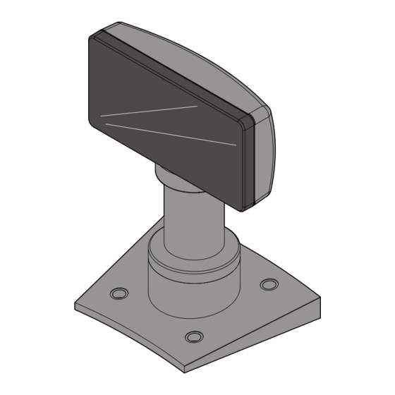
Chapter 3: Hardware Installation Installation Procedures 1. Locate the Display Mount within 4 meters (13 ft.) of the host terminal. 2. Determine if the cable should be routed down through the mounting surface or if it should be run on top of the surface. Drill a hole if necessary. 3. - Page 27 Chapter 3: Hardware Installation 5. Assemble the post components. Note: The raised extension of the Display Swivel is oriented toward the front of the unit, which permits the Display to be tilted to the rear. Raised extension faces the front of the display Display Swivel 33180 6.
- Page 28 Chapter 3: Hardware Installation 7. Connect the display to the post assembly 33181 8. Connect the terminal end of the Display Cable to the host terminal. RS–232 Interface (Powered) • Connect the I/F cable to a powered RS–232 connector on the terminal. RS–232 Interface (Non–Powered) •...
-
Page 29: Diagnostics
Chapter 3: Hardware Installation USB Interface (Powered) • Connect the I/F cable to a powered 12V USB + Power connector on the terminal. USB Interface (Non–Powered) • Connect the I/F cable to a non–powered USB connector on the terminal. Connect a Power Brick to the I/F cable and an AC outlet. Diagnostics The 5976 Customer Display has internal Power Up Diagnostics that occur soon after power–up or if a Reset Display command is received from the host software. -
Page 31: Chapter 4: Hardware Service
Hardware Service Chapter 4: Safety Requirements Carefully follow these safety requirements before servicing the Retail Display: This device does not contain any user serviceable parts and should only Warning: be serviced by a qualified service technician. Caution: Before servicing the display, disconnect the AC power cord from the retail terminal or PC to which the display is connected. -
Page 32: Servicing The Display
On power–up, the unit displays the firmware part number for 2 seconds, then lights all pixels for 2 seconds, then goes blank and awaits commands from the host. Troubleshooting Procedures The NCR 5976 Customer Display requires minimal maintenance. Should the display malfunction, adhere to the procedures in the following troubleshooting chart. Symptom... -
Page 33: Chapter 5: Programming
Programming Chapter 5: Host/Retail Display Command Interface The Retail Display accepts two types of data: display data and command data. If a byte received from the host is any character except the ESC (0x1B) character, it • is processed as a character and displayed on the Retail Display. If an ESC character (0x1B) is received, the subsequent byte(s) is processed as a •... -
Page 34: Retail Display Commands
Chapter 5: Programming Retail Display Commands The following table describes the Retail Display commands supported: Command Function 1B 01 Reset Display 1B 02 Erase Display 1B 03 Invalid Command 1B 04 Set Diagnostic State 1B 05 Set Display State On 1B 06 Set Low Power State On (Default) 1B 07... - Page 35 Chapter 5: Programming Command Function 1B 23 Select Character Set 4 (External Memory required) 1B 24 Select Character Set 5 (External Memory required) 1B 25 Select Character Set 6 (External Memory required) 1B 26 Select Character Set 7 (External Memory required) 1B 27 Select Character Set 8 (External Memory required) 1B 28...
-
Page 36: Reset Display
Chapter 5: Programming Reset Display Format 1B 01 Returns xx yy zz xx=microcontroller status 00=OK If failure occurs, the firmware performs a loop forever. yy=Flash status 00=Ok, present 01=Not present FF=Failure zz=number (in hexadecimal) of character sets available in the Flash 00=10 Description This command executes the power–down power–up diagnostic sequence. -
Page 37: Invalid Command
This state is exclusive from the On and Low Power states. This command causes the firmware to display the current NCR firmware part number of the device (for example, the current firmware part number for the device is 497–0408199) for five seconds and then step through each installed 256–character set (default and user... -
Page 38: Set Low Power State On
Chapter 5: Programming Set Low Power State On Format 1B 06 Description This state is used to reduce Retail Display power consumption and extend the life of the Retail Display. Power is only removed from the display and the display is not refreshed. -
Page 39: Set Screen Save Blank
Chapter 5: Programming Set Screen Save Blank Format 1B 09 Description This command is intended to preserve the life of the display hardware unit. The firmware maintains a five–minute timer that triggers this feature. The Screen Save feature can be disabled through a command from the host software. When the feature is not disabled, two specific options exist. -
Page 40: Disable Screen Save Option
Chapter 5: Programming Disable Screen Save option Format 1B 0C Description The firmware ceases to keep time for the screen save activity from the host software and the display neither goes blank nor begins to walk due to inactivity from the host. This command can be canceled by the Turn on Screen Save, Set Screen Save Blank, and Set Screen Save Walk commands. -
Page 41: Move Cursor Left
Chapter 5: Programming Move Cursor Left Format 1B 0F Description This moves the cursor one position to the left. When the cursor is at the left end of the upper line, it moves to the right end of the lower line. When the cursor is at the left end of the lower line, it moves to the right end of the upper line. -
Page 42: Move Cursor Down
5-10 Chapter 5: Programming Move Cursor Down Format 1B 12 Description This command moves the cursor down one line. When the cursor is on the lower line, the cursor is moved to the same column on the upper line. The cursor location always indicates the position of the next character to be displayed, whether the cursor is enabled and blinking or not. -
Page 43: Query All Character Set Code Name
Chapter 5: Programming 5-11 Query All Character Set Code Name Format 1B 14 Returns All character set codename in HEX format padded by 0x2C Description This command is a request for the Retail Display to return all the available character set codes stored in its memory. -
Page 44: Read Display Id String
Read Display ID String Format 1B 19 Returns “NCR 5976, 497-0478048,V1.13.01,<S/N:(11 bytes)>” in Hex format Note: The quotation marks “” are not part of the string and are not returned. Description This command is a request for the Retail Display to return an ASCII string with detailed product information. -
Page 45: Read Serial Number
Chapter 5: Programming 5-13 Character sets 7 through 20 are only valid if extra character sets are present. Character set selection is dynamic. Host software can switch between character sets at any time. Switching between sets does not erase or change the display. This means characters from multiple character sets may be on a display. -
Page 46: Character Sets
Code 775 (Baltic) o Code 852 (Polish) o Code 853 (Multilingual Latin with € symbol) Note: To download other code pages, see the NCR website: http://www5.ncr.com/support/support_drivers_patches.asp. If your code page requirements are not included in the website, please file for a SCER request. - Page 47 Chapter 5: Programming 5-15...
- Page 48 5-16 Chapter 5: Programming...
- Page 49 Chapter 5: Programming 5-17...
- Page 50 5-18 Chapter 5: Programming...
- Page 51 Chapter 5: Programming 5-19...
- Page 52 5-20 Chapter 5: Programming...
- Page 53 Chapter 5: Programming 5-21...
-
Page 54: Code Page 101 Katakana
5-22 Chapter 5: Programming Code Page 101 Katakana... - Page 55 Chapter 5: Programming 5-23...
- Page 56 5-24 Chapter 5: Programming...
- Page 57 Chapter 5: Programming 5-25...
- Page 58 5-26 Chapter 5: Programming...
- Page 59 Chapter 5: Programming 5-27...
- Page 60 5-28 Chapter 5: Programming...
- Page 61 Chapter 5: Programming 5-29...
- Page 62 5-30 Chapter 5: Programming...
- Page 63 Chapter 5: Programming 5-31...
-
Page 64: Code Page 866 (Cyrillic)
5-32 Chapter 5: Programming Code Page 866 (Cyrillic) - Page 65 Chapter 5: Programming 5-33...
- Page 66 5-34 Chapter 5: Programming...
- Page 67 Chapter 5: Programming 5-35...
- Page 68 5-36 Chapter 5: Programming...
- Page 69 Chapter 5: Programming 5-37...
- Page 70 5-38 Chapter 5: Programming...
- Page 71 Chapter 5: Programming 5-39...
-
Page 72: Code Page 775 (Baltic)
5-40 Chapter 5: Programming Code Page 775 (Baltic) - Page 73 Chapter 5: Programming 5-41...
- Page 74 5-42 Chapter 5: Programming...
- Page 75 Chapter 5: Programming 5-43...
- Page 76 5-44 Chapter 5: Programming...
- Page 77 Chapter 5: Programming 5-45...
- Page 78 5-46 Chapter 5: Programming...
- Page 79 Chapter 5: Programming 5-47...
-
Page 80: Code Page 852 (Polish)
5-48 Chapter 5: Programming Code Page 852 (Polish) - Page 81 Chapter 5: Programming 5-49...
- Page 82 5-50 Chapter 5: Programming...
- Page 83 Chapter 5: Programming 5-51...
- Page 84 5-52 Chapter 5: Programming...
- Page 85 Chapter 5: Programming 5-53...
- Page 86 5-54 Chapter 5: Programming...
- Page 87 Chapter 5: Programming 5-55...
-
Page 88: Code Page 853 (Multilingual Latin With € Symbol)
5-56 Chapter 5: Programming Code Page 853 (Multilingual Latin with € symbol) - Page 89 Chapter 5: Programming 5-57...
- Page 90 5-58 Chapter 5: Programming...
- Page 91 Chapter 5: Programming 5-59...
- Page 92 5-60 Chapter 5: Programming...
- Page 93 Chapter 5: Programming 5-61...
- Page 94 5-62 Chapter 5: Programming...
- Page 95 Chapter 5: Programming 5-63...
-
Page 97: Chapter 6: Retail Platform Software
Customers are required to download and install the latest version of the NCR Retail Platform Software from http://www5.ncr.com/support/support_drivers_patches.asp. The software includes support for the 5976 line display device. -
Page 98: Installation Procedure
Chapter 6: Retail Platform Software Installation Procedure Downloading the Installer for Retail Platform Software The 5976 Retail Platform Software can be downloaded from the NCR website. Perform these steps to download the software: 1. Go to http://www5.ncr.com/support/support_drivers_patches.asp. 2. Select Retail Support Files (Drivers, Firmware, Operating Systems, Platform Software (OPOS/JavaPOS), BIOS, etc.). -
Page 99: Installing The Retail Platform Software
Installing the Retail Platform Software Windows For instructions on how to install the Retail Platform Software for Windows (RPSW), refer to Chapter 2, “RPSW Installation” in the NCR Retail Platform Software for Windows User Guide (B005–0000–1634). Linux Before you install the Retail Platform Software for Linux (RPSL), make sure to provide... - Page 100 Note: In the <java directory>, specify the directory path of the java binary. Only include this parameter if $JAVA_HOME is not set. Note: In the <path to package>, specify the directory path of the installer package that you downloaded from the NCR website. The Welcome Screen displays.
- Page 101 Chapter 6: Retail Platform Software 6. Select Next. 7. Specify the directory where you want to install the RPSL. The default directory is . To locate another destination directory, select Browse. /opt/NCR/RPSfL 8. Select the terminal class where your 5976 display is connected.
- Page 102 Chapter 6: Retail Platform Software 9. At the Setup Type window, select the installation type that you prefer. 10. Select Next. 11. The application displays your installation details for you to confirm. If you want to change some options, select Back. 12.
- Page 103 Chapter 6: Retail Platform Software The installation setup begins. 13. Upon successful installation, the application confirms the completion. Select Finish.
- Page 104 Note: In the <java directory>, specify the directory path of the java binary. Only include this parameter if $JAVA_HOME is not set. Note: In the <path to package>, specify the directory path of the installer package that you downloaded from the NCR website.
- Page 105 6. The application displays the Welcome message and begins to guide you in the installation process. Press 1. Specify the directory where you want to install the RPSL. The default directory is /opt/NCR/RPSfL. To accept the default directory, press Enter. •...
- Page 106 6-10 Chapter 6: Retail Platform Software 10. After selecting your terminal class, press 0 (zero). 11. Press 1 to continue the installation process. 12. Select the installation type that you prefer. Each parameter is assigned a number. From your keyboard, press the number that corresponds to your desired parameter.
- Page 107 Chapter 6: Retail Platform Software 6-11 13. The application displays the installation details for you to confirm.
- Page 108 6-12 Chapter 6: Retail Platform Software 14. After verifying information, press 1 to continue the installation process. The installation setup begins. 15. Upon successful installation, the application displays the following message. Press 3 to exit program.
-
Page 109: Uninstalling The Retail Platform Software
_uninst installation. The default install directory is /opt/NCR/RPSfL. Example: Assuming that default install directory was selected during installation, enter the following command to uninstall the RPSL: /usr/java/jvm/bin/java –jar /opt/NCR/RPSfL/_uninst/uninstall.jar... -
Page 111: Chapter 7: Software Utility
Manual firmware shift • The software supports flashing of firmware into the device connected through the USB or RS–232 serial port. Note: For more information about RomFlasher, refer to the in the NCR ReadMe.txt website, http://www5.ncr.com/support/support_drivers_patches.asp?Class=External/PeripheralsLineD isplay5976\display. -
Page 112: Installation Procedure
The Software Utility installation includes downloading the installer from the NCR website. The following sections define the installation process. Downloading the Installer The 5976 Line Display Utility can be downloaded from the NCR website. Perform these steps to download the utility: 1. Go to http://www5.ncr.com/support/support_drivers_patches.asp. -
Page 113: Installing The Software
Chapter 7: Software Utility Installing the Software Windows 1. Run the installer. The 5976 Utilities Setup window displays. Note: The default install directory is . To C:\Program Files\RomFlasher 5976 change the location, select Browse. 2. Select Install. Upon successful installation, the following window displays. -
Page 114: Linux
Chapter 7: Software Utility Linux 1. Open a terminal. Install the software by entering the command: rpm –ivh RomFlasher.rpm... -
Page 115: Uninstalling The Software
Chapter 7: Software Utility Uninstalling the Software Windows To uninstall the Software utility, select StartAll ProgramsNCRRomFlasher 5976Uninstall. The Uninstall window displays to verify. Select Yes and the uninstalling process begins. • Select No and the process cancels. • Linux 1. Open a terminal. -
Page 116: Device Firmware
Note: Take note of the firmware version currently installed on your device. Verify if it matches with the latest released version that can be found on the NCR 5976 Support page. If they do not match, it is recommended to update the firmware of your device. - Page 117 Chapter 7: Software Utility 7. Save the downloaded file ( file) to a working directory on the terminal hard *.fif drive. Note: The files can be extracted to and run from a Flash Drive, CDROM, or network if desired. 8. Flash the downloaded firmware to the 5976 display device. Note: For instructions on how to flash the downloaded firmware, refer to the “ROM Flasher”...
-
Page 118: Rom Flasher
You can update the 5976 2x20 LCD firmware by using the ROM Flasher utility. To update the device firmware, perform the following steps: 1. Launch the 5976 2x20 ROM Flasher application by selecting from the Start menu StartAll ProgramsNCRRomFlasher 5976RomFlasher. The application displays the ROM Flasher user interface. - Page 119 Chapter 7: Software Utility 2. To load the firmware ( file) into the ROM Flasher, select Browse beside the *.fif ROM File field and locate the working directory where you extracted your firmware files. 3. From the Interface section, select the port where the device is connected. USB—select this option if you are running a USB interface.
- Page 120 7-10 Chapter 7: Software Utility 6. Select Flash. The firmware flashing progress is displayed and updated at the bottom field. A 100% Flash Progress is shown if the firmware was successfully flashed to the device. The following screenshot illustrates an ongoing firmware flashing.
- Page 121 Chapter 7: Software Utility 7-11 Upon successful firmware flashing, the application displays the Flash Progress with 100%. Note: If the firmware is not successfully flashed or the loaded firmware version is older than the current firmware of the devices, the application displays the error information in the Error box.
-
Page 122: Shift Firmware To Compatibility Mode
7-12 Chapter 7: Software Utility Shift Firmware to Compatibility Mode After flashing firmware to the line display device, perform the following steps to shift the firmware mode to compatibility: 1. Select the device row from the device list with (Native) suffix. - Page 123 Chapter 7: Software Utility 7-13 2. Select Shift button. The device list is refreshed with the shifted device firmware.
-
Page 124: Shift Firmware To Native Mode
7-14 Chapter 7: Software Utility Shift Firmware to Native Mode After flashing firmware to the line display device, perform the following steps to shift the firmware mode to native: 1. Select the device row from the device list with (Compatibility) suffix. - Page 125 Chapter 7: Software Utility 7-15 2. Select Shift button. The device list is refreshed with the shifted device firmware.
-
Page 126: Code Page Utility
Multilingual Latin with € symbol (853) • Polish (852) • Note: To download other code pages, refer to the NCR website: http://www5.ncr.com/support/support_drivers_patches.asp?Class=External/PeripheralsLineD isplay5976\display. If your code page requirements are not included in the website, please file for a SCER request. -
Page 127: Generating Code Page
Chapter 7: Software Utility 7-17 5. Select 5976. The NCR 5976 Support page displays. 6. From the Code Pages list, select the Code Page that you want to download. 7. Save the downloaded file ( file) to a working directory on the terminal hard *.dat... - Page 128 7-18 Chapter 7: Software Utility 2. Select 5976 CodePage Flasher from the ROM Flasher window. The application displays the 5976 Utility window. Note: The following window displays the code pages for a USB interface connection. To display the existing code pages for the RS–232C connection, select RS–232C from the Interface field.
- Page 129 Chapter 7: Software Utility 7-19 6. Select Generate. You can use this output file to add a new output file to a device’s code page list or to replace an existing file.
-
Page 130: Adding Code Pages
7-20 Chapter 7: Software Utility Adding Code Pages The Code Page Utility permits users to add character sets or replace existing character sets by flashing code pages into devices connected through a USB or RS–232C serial port. The code page used can be a direct output from the Code Page Generator or a predefined code page file which the user can load into the Code Page flasher. - Page 131 Chapter 7: Software Utility 7-21 4. Select Flash. The application displays the progress beside the Flash button. Only one device at a time can be flashed with a code page. Make sure to detach the devices you do not wish to flash with the code page.
- Page 132 7-22 Chapter 7: Software Utility 5. Select Refresh to confirm that the code page is added to the Additional list.
-
Page 133: Replacing Default Code Pages
Chapter 7: Software Utility 7-23 Replacing Default Code Pages 1. To replace the default code page, select one of the built–in code pages. 2. Perform the same steps on how to generate the output file. Refer to “Generating Code Page” section in this chapter for instructions. - Page 134 7-24 Chapter 7: Software Utility 3. On flash, select Yes when prompted to replace the default code page.
- Page 135 Chapter 7: Software Utility 7-25 4. Check the code page in the Built–in list box.
-
Page 137: Chapter 8: Service Support Utility
Service Support Utility Chapter 8: Introduction The Service Support Utility configures the following settings of the NCR 5976 Line Display device: NCR5976LDServiceSupport Flash Firmware Flash Additional Code Page Replace Existing Code Page Generate Code Page Set Brightness Level ... -
Page 138: Rom Flasher And Service Support Utility
Chapter 8: Service Support Utility Rom Flasher and Service Support Utility RomFlasher provides the feature of saving settings for the Service Support Utility to be applied to the line display devices. The following settings are saved: Firmware of the device •... -
Page 139: Installation Procedure
1. Go to http://www5.ncr.com/support/support_drivers_patches.asp. 2. Select Retail Support Files (Drivers, Firmware, Operating Systems, Platform Software (OPOS/JavaPOS), BIOS, etc.). 3. Select NCR RealPOS and SelfServ Peripherals (Firmware, Drivers, Utilities). 4. Select Line Displays. 5. Select 5976. 6. Download the installer by selecting one of the following options: NCR5976LDServiceSupport.exe (for Windows) -
Page 140: Installing The Software
Chapter 8: Service Support Utility Installing the Software Windows 1. Run the installer of the Service Support Utility. The application displays the Welcome screen. 2. Select Next. The License Agreement displays. - Page 141 Chapter 8: Service Support Utility 8-5 3. Select I accept the terms in the license agreement. 4. After agreeing to the terms in the license agreement, the application displays the Customer Information window to ask for your name and the name of your organization.
- Page 142 Chapter 8: Service Support Utility 7. At the Setup Type window, select the setup type that you desire. Select Next. 8. Select Install to start installation.
- Page 143 Chapter 8: Service Support Utility 8-7 The application displays the installation progress in the following screen. 9. Upon successful installation, the application displays the following window. Select Finish.
-
Page 144: Linux
Chapter 8: Service Support Utility Linux 1. Open a terminal. 2. Install the software by entering the command: rpm –ivh NCR5976LDServiceSupport.rpm... -
Page 145: Uninstalling The Software
Chapter 8: Service Support Utility 8-9 Uninstalling the Software Windows 1. From the Start menu, select Control Panel Add or Remove Programs Change or Remove Programs. 2. From the currently installed program list, select NCR5976LDServiceSupport. 3. Select Remove. 4. -
Page 146: Control The Service
Chapter 8: Service Support Utility 8-10 Control the Service The configuration settings of the device are automatically activated in the background upon terminal start–up. Stopping the Service To stop the service from running automatically, perform the following steps. Note: The change of start–up type takes effect upon system reboot. Windows 1. -
Page 147: Running The Service
Chapter 8: Service Support Utility 8-11 Running the Service To run the service manually, perform the following steps. Windows 1. From the Start menu, select Control Panel Performance and Maintenance Administrative Tools Services. 2. From the services list, select NCR5976LDServiceSupport. Note: If the Service status is already started, select Stop. - Page 148 Chapter 8: Service Support Utility 8-12 Using the Default Settings Note: This feature is supported in versions 1.1 or higher. To use the default settings for Windows or Linux, perform either of the following steps. Windows 1. Locate the folder in your Windows directory. 5976LDSettings 2.
- Page 149 Chapter 8: Service Support Utility 8-13 Compatibility Support The 5976 Compatibility Support is a software feature that provides convenience to the existing 5975 users who want to replace their line displays to 5976. This feature enables the 5976 to be backward–compatible with the previous 5975 functions and installed software especially the Retail Platform Software (RPS).
- Page 150 Chapter 8: Service Support Utility 8-14 Brightness Level Adjustment On power up, the default brightness setting is 2 (40%). Change the Brightness Level To adjust the brightness level of the device, perform these steps. Windows 1. Go to Windows directory ( C:\Windows 2.
Need help?
Do you have a question about the RealPOS 5976-1 Series and is the answer not in the manual?
Questions and answers