Advertisement
UT351/352
SOUND LEVEL METER
OPERATING MANUAL
Display Symbols
B.
(see figure 2)
14
13
12
11
10
9
15
8
16
7
6
17
5
18
4
19
3
20
2
21
22
23
1
figure 2
4
Overview
Sound Level Meter Model UT351 and UT352 (hereafter
referred to as "the Meter") is a stable, safe and reliable
sound level meter. The Meter is suitable to use in noise
control, quality control, health care and all different kind of
environmental noise testing. For example: factory, road,
family, musical instrument and all kind of places which
need noise testing.
Unpacking Inspection
Open the package case and take out the Meter. Check
the following items carefully to see any missing or
damaged part:
Item
Description
Qty
1
English Operating Manual
1 piece
2
Windscreen
1 piece
3
1.5V Batteries (AA)
4 pieces
In the event you find any missing or damage, please
contact your dealer immediately.
Rules For Safe Operation
Before using the Meter inspect the case and
accessories. Do not use the Meter if it is damaged, LCD
cannot display, the case (or part of the case) is removed
or you consider the Meter does not work properly. Look
for cracks or missing plastic.
When using the Meter, must follow the instruction
manual.
The internal circuit of the Meter shall not be altered at
will to avoid damage of the Meter and any accident.
Replace the battery as soon as the battery indicator
appears.
Turn the Meter power off when it is not in use and take
out the battery when not using for a long time.
Do not use or store the Meter in an environment of
high temperature, humidity, explosive, inflammable and
strong magnetic field. The performance of the Meter
may deteriorate after dampened.
1
No.
Meaning
1
Data Store is full
2
Date and Time display
3
Data Store
4
Decibel
5
C-Weighting
6
A-Weighting
7
Sound value display
8
Range display
9
Over range
10
Slow response
11
Fast response
12
Low battery display
13
Data Hold is on
14
Auto power off enabled
15
Under range
16
Analogue bar graph display
17
Symbol of Sound Pressure Level
18
Auto ranging enabled
19
Date display
20
Time display
21
Maximum value display
22
Minimum value display
23
Data Store enabled
5
Soft cloth and mild detergent should be used to clean
the surface of the Meter when servicing. No abrasive
and solvent should be used to prevent the surface of the
Meter from corrosion, damage and accident.
Constantly check the battery as it may leak when it has
been using for some time, replace the battery as soon
as leaking appears. A leaking battery will damage the
Meter.
2
Side Panel (see figure 3)
External DC6V
DC Output Terminal
AC Output Terminal
CAL potentiometer
figure 3
1. DC Output Terminal: DC analogue signal output.
Output impedance is around 100Ω (10mV/dB)
2. AC Output Terminal: AC analogue signal output.
Output impedance is around 600Ω (0.707V/ each
range scale)
3. CAL potentiometer: Calibration
4. External DC6V:Using power adaptor DC6V, output
plug (
6
International Electrical Symbols
Conforms to Standards of European Union
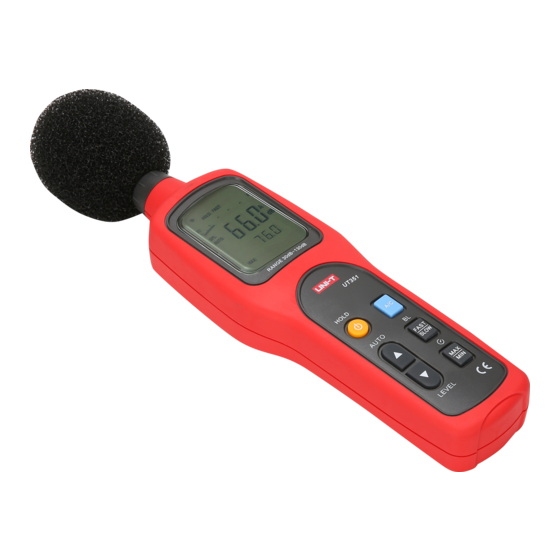
The Meter Structure (see figure 1)
figure 1
A. Meter Front
1. Housing
2. Windscreen
3. Microphone
4. LCD Display
5. Functional Buttons
6. Signal output and power terminals
3
Measurement Operation and Functional
Buttons
Below table indicated for information about the functional
button operations
Button
Operation Performed
HOLD
Turn the Meter on and off. Press once
to turn the Meter on. Press and hold for
around 1 second to turn the Meter off.
HOLD feature: During sound measure
ment, press once to freeze the current
reading in the display. Press the button
again to resume normal operation.
A/C
During sound measurement, press
A/C button to select "A" or "C" frequency
weighting. With "A" weighting selected,
the frequency response of the Meter is
similar to the response of the human ear.
"A" weighting is commonly used for envi
ronmental or hearing conservation
programs 'C" Weighting is a much flatter
response and is suitable for the sound
level analysis of machines, engines, etc.
Most noise measurements are performed
using "A" Weighting and SLOW
Response.
For the Model UT352, press A/C button
also could recall and clear data:
RECALL:
Press and hold this button, the LCD
displays the last data stored and the
index number.
Press
button to recall additional
stored reading.
Press
button to exit the RECALL
mode
CLR:
Press and hold A/C button when turning
on the Meter until the LCD displays CLR
and RECORD. All the data stored will
be cleared.
7
Advertisement
Table of Contents

Related Manuals for UNI-T UT351


Summary of Contents for UNI-T UT351
- Page 1 Overview Soft cloth and mild detergent should be used to clean the surface of the Meter when servicing. No abrasive Sound Level Meter Model UT351 and UT352 (hereafter Conforms to Standards of European Union UT351/352 and solvent should be used to prevent the surface of the referred to as “the Meter”) is a stable, safe and reliable...
- Page 2 B.Environmental Requirements Button Operation Performed Button Operation Performed For indoor use only. Press to selection of Auto ranging, Manual MAX/ LEVEL Press MAX/MIN button again. The MIN Altitude: 2000m ranging. icon will appear on the display. The read Temperature and humidity: The Meter is default to auto ranging.
Need help?
Do you have a question about the UT351 and is the answer not in the manual?
Questions and answers