
Related Manuals for UNI-T UT712


Summary of Contents for UNI-T UT712
-
Page 1: Table Of Contents
Model UT712: Users Manual Table of Contents Title Page Introduction Safety Information The Calibrator Structure LCD Display Turning the Calibrator On Measuring DC Volts (V and COM jack) Sourcing DC Volts (V and COM jack) Measuring DC mA (mA and COM jack) -
Page 2: Title Page
Model UT712: OPERATING MANUAL Title Page Replacing the Battery Specifications DC Voltage and DC Current Input DC Voltage and DC Current Output General Specifications... -
Page 3: Introduction
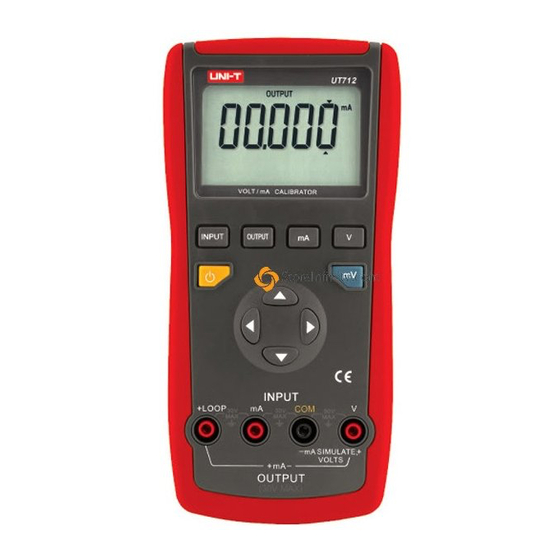
Model UT712: OPERATING MANUAL Introduction The Uni-Trend UT712 Volt/mA Calibrator is a source and measurement tool for 0 to 20mA current loop testing and DC Voltage from 0 to 20V. The calibrator does not source and measure simultaneously. Your calibrator has a unique design and large LCD can read the data clearly. -
Page 4: Safety Information
Model UT712: OPERATING MANUAL International Symbols Symbol Meaning Earth ground Refer to this user manual for information about this feature. Battery Double insulated Conforms to European Union directives. Safety Information Use the calibrator only as specified in this user manual, otherwise the protection provided by the calibrator may be impaired. - Page 5 Model UT712: OPERATING MANUAL Warning To avoid possible electric shock or personal injury: Never apply more than 30V between any two jacks (terminals), or between any jack and earth ground. Make sure the battery door is closed before you operate the calibrator.
- Page 6 Model UT712: OPERATING MANUAL Constantly check the battery as it may leak when it has not been using for some time, replace the battery as soon as leaking appears. A leaking battery will damage the calibrator. The internal circuit of the calibrator shall not be altered at will to avoid damage of the calibrator and any acccident.
-
Page 7: The Calibrator Structure
Model UT712: OPERATING MANUAL The Calibrator Structure LCD Display Press to select mA measurement Press to select V INPUT Button measurement Press to select mV measurement Press to change the cursor location. Press to scroll up/down. Hold down to Output/Input Jacks scroll faster. - Page 8 Model UT712: OPERATING MANUAL Figure 2 OUTPUT The calibrator is in output mode INPUT The calibrator is in input mode mV, V, mA The measurement unit of the current reading Battery is low. Replace the battery The current cursor location...
-
Page 9: Turning The Calibrator On
Model UT712: OPERATING MANUAL Turning the Calibrator On Press the yellow pushbutton to turn the calibrator on and off. Turn off the calibrator when not in use. Measuring DC Volts (V and COM jack) 2.Press so that INPUT is on the display INPUT 1.Press to turn the... -
Page 10: Sourcing Dc Volts (V And Com Jack)
Model UT712: OPERATING MANUAL Sourcing DC Volts (V and COM jack) O U T P U T The current cursor location 2.Press so that mV or V depending OUTPUT is on the on range display 3.Press to toggle mV 1.Press to turn the... -
Page 11: Measuring Dc Ma (Ma And Com Jack)
Model UT712: OPERATING MANUAL Measuring DC mA (mA and COM jack) display “mA “ INPUT 3.Press to choose 2.Press so that INPUT mA range is on the display 1.Press to turn the 4.Insert the test leads calibrator on and off... -
Page 12: Measuring Dc Ma With Loop Power (Loop And Ma Jack)
Model UT712: OPERATING MANUAL Measuring DC mA with Loop Power (LOOP and mA jack) display “mA “ INPUT 2.Press so that INPUT 3.Press to choose is on the display mA range 1.Press to turn the 4.Insert the test leads calibrator on and off... -
Page 13: Using The Current Output Modes
Model UT712: OPERATING MANUAL Using the Current Output Modes In source mode, the calibrator supplies the current. In simulate mode, the calibrator simulates a two-wire transmitter in an externally-powered current loop Sourcing mA Use source mode whenever you need to supply current into a passive circuit such as a current loop with no loop supply. - Page 14 Model UT712: OPERATING MANUAL OUTPUT display “mA “ 2.Press so that The current cursor OUTPUT is on the location display 3.Press to choose mA 1.Press to turn the calibrator on and off 4.Insert the test leads Press as shown change the cursor location.
-
Page 15: Simulating A Transmitter
Model UT712: OPERATING MANUAL Simulating a Transmitter Use simulate mode when an external 24 to 30V loop power supply is available. Insert the test leads into the mA SIMULATE – and + jacks as shown below figure 8. OUTPUT display “mA “... -
Page 16: Maintenance
Model UT712: OPERATING MANUAL Maintenance Below provides basic maintenance information including battery and fuse replacement instruction. Warning Do not attempt to repair or service your Meter unless you are qualified to do so and have the relevant calibration, performance test, and service information. -
Page 17: Replacing The Fuses
Model UT712: OPERATING MANUAL Replacing the Fuses Warning To avoid electrical shock or arc blast, or personal injury or damage to the Meter, use specified fuses ONLY in accordance with the following procedure. Follow Figure 9 and proceed as follows to replace the Meter’s fuse: l Turn the calibrator off and remove all connections from the terminals. - Page 18 Model UT712: OPERATING MANUAL Fuse 1: 125mA, 250V, fast type fuse, ø5×20mm Fuse 2: 125mA, 250V, fast type fuse, ø5×20mm l Rejoin the case bottom and case top, battery compartment and case bottom, and install all the screws. Figure 9...
-
Page 19: Replacing The Battery
Model UT712: OPERATING MANUAL Replacing the Battery Warning To avoid false readings, which could lead to possible electric shock or personal injury, replace the battery as soon as the battery indicator ( ) appears. Follow Figure 9 and proceed as follows to replace the battery. - Page 20 Model UT712: OPERATING MANUAL Figure 10...
-
Page 21: Specifications
Model UT712: OPERATING MANUAL Specifications Specifications are based on a one year calibration cycle and apply from +18 unless stated otherwise. DC Voltage and DC Current Input Input Range Input Range Resolution Accuracy DC Voltage 200mV (0.00~200.00) mV 0.01mV ±(0.04% (0.000~20.000) V... -
Page 22: Dc Voltage And Dc Current Output
Model UT712: OPERATING MANUAL DC Voltage and DC Current Output Output Range Output Range Resolution Accuracy 200mV 0.01mV DC Voltage (0.00~200.00) mV 0.001V (0.000~20.000) V ±(0.04% readings 20mA 0.001mA DC Current (0.000~20.000) mA +3 digits) Simulate 20mA 0.001mA (0.000~20.000) mA mode ±10%... -
Page 23: General Specifications
Model UT712: OPERATING MANUAL General Specifications l Resolution: DC Voltage:0.01mV (200mV range), 0.001V (20V range) DC Current:0.001mA (20mA Range) l Maximum voltage applied between any jack and earth ground or between any two jacks: 30V l Storage temperature: -10 to 55... - Page 24 Model UT712: OPERATING MANUAL Copyright 2008 Uni-Trend Group Limited. All rights reserved. Manufacturer: Uni-Trend Technology (Dongguan) Limited Dong Fang Da Dao Bei Shan Dong Fang Industrial Development District Hu Men Town, Dongguan City Guang Dong Province China Postal Code: 523 925...
Need help?
Do you have a question about the UT712 and is the answer not in the manual?
Questions and answers