Table of Contents
Advertisement
Quick Links
Advertisement
Table of Contents

Related Manuals for UNI-T UT3550


Summary of Contents for UNI-T UT3550
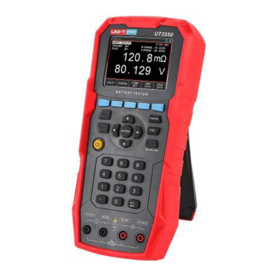
- Page 1 UT3550 Battery Tester User Manual www.uni-trend.com.com...
-
Page 2: Preface
If the original purchaser sells or transfers the product to a third party within one year from the date of purchase of the product, the warranty period of one year shall be from the date of the original purchase from UNI-T or an authorized UNl-T distributor. -
Page 3: Guarantee Limit
This warranty is written by UNI-T for this product and it is used to substitute any other express or implied warranties. UNI-T and its distributors do not offer any implied warranties for merchantability or applicability purposes. -
Page 4: Safety Instructions
Warning: For the instrument model UT3550 , do not apply AC voltage and DC voltage exceeding100V to the test terminal, otherwise the instrument will be damaged. Waste Electrical and Electronic Equipment (WEEE) Directive 2002/96/EC... -
Page 5: Table Of Contents
UT3550 Battery Tester Users Manual Table of Contents Preface ........................................2 Copyright Information ..................................2 Warranty Service ....................................2 Guarantee Limit ....................................3 Safety Instructions ....................................4 Table of Contents ....................................5 Introduction ....................................7 1.1 Product Introduction ................................. 7 1.2 Main Function .................................... - Page 6 UT3550 Battery Tester Users Manual 4.2 Save and View Data ................................. 19 4.3 Screenshot Function ................................19 [Utility] Setting ..................................... 20 5.1 Parameters of Measurement ..............................20 5.1.1 Timer ....................................20 5.1.2 Beep ....................................20 Comparator Sorting ..................................21 6.1 Comparator Setting ................................. 21 6.1.1...
-
Page 7: Introduction
This chapter includes: Product Introduction Main function Front panel & Interface panel 1.1 Product Introduction UT3550 battery internal tester, measured voltage range is 100V. See the below table, more specific technical index refer to the last chapter. Model Accuracy Measurement Range Resistance:±0.5%rdg±5dgt... -
Page 8: System
UT3550 Battery Tester Users Manual System Keypad lock function Switch Chinese/English language Date and time setup Administrator and user account, administrator account can set code Backlight setup Auto power off time setup 1.3.1 Remote Control Support maximum 115200bps baud rate, compatible with SCPI protocol, ASCII transmission. -
Page 9: Interface Panel
UT3550 Battery Tester Users Manual Introduction of Symbol Symbol Description U disk inserts into instrument, it can save data and screenshot Key lock function enabled There is no measured value, measurement line and object does not connect It presents measured value is qualified within comparator range... -
Page 10: Inspection And Installation
Requirements of Power Supply It has standard power adapter for UT3550 battery internal resistance tester. When connect with external power supply, the instrument will use external power supply and cell stop supply power automatically. External power supply also can charge up built-in lithium battery. It is suggested that use our company’s specialized power adaper. -
Page 11: Operating Environment
UT3550 Battery Tester Users Manual Operating Environment UT3550 series must be used under the following environmental conditions: Temperature:0℃~40℃ Humidity:10~80%RH Altitude:0~2000 meter Cleaning To prevent from the risk of electric shock, please pull out power line before cleaning. Please use a clean cloth dipped in clean water to clean the cover and panel. -
Page 12: Tilt Stand
UT3550 Battery Tester Users Manual 1. Take down screw 2. Push the strap 3. Push down and then pull out the strap Tilt Stand Figure 2-7-a Tilt Stand Closed Position Figure 2-7-b Tilt Stand Open Position... -
Page 13: Preparation Before Measurement
3.1.2 Introduction of Test Lead UT3550 series battery internal resistance tester is equipped with UT-L84 kalvin clips and UT- L86 test pen-crown probe, which is convenient for users to measure more professionally. Figure 3-1-2 a UT-L84 Kalvin Clips Test Wire Figure 3-1-2 b UT-L86 Test Pen-Crown Probe 3.1.3... -
Page 14: Measurement Method Of Dut
UT3550 Battery Tester Users Manual Note: In order to ensure the accuracy of the instrument, please use the attached test lead for testing. Warning: It is pronhibited to connect the AC current and voltage source directly to the test terminals... -
Page 15: Set Zero And Calibration
UT3550 Battery Tester Users Manual Set Zero and Calibration Before testing, please perform the short circuit zeroing step to remove the stray resistance and bias voltage caused by the test lead or external environment factors. The measured resistance value may be very small, such as 3mΩ and 30mΩ range. When the test current flows through the resistance, the voltage signal generated will be very weak, and the maximum is only a few mV, so the position, length and shape of the test lead may all have effects on the measurement. - Page 16 UT3550 Battery Tester Users Manual Figure 3-3-1-a Crown Probe Test Pen Short Circuit Diagram a Second, apply force in the direction of the arrow shown in Figure 3-3-1-b to make the surface of the object at the third red point contact, that is, the periphery probe is in contact with the peripheral probe (Source and Source).
-
Page 17: [Test] Measurement Page
UT3550 Battery Tester Users Manual [Test] Measurement Page <Test>page <Test> page is mainly used to display the measurement and sorting results. Three common functions can be set on this page, including: TRIGGER - The Trigger Mode of the Measurement FUNC –... -
Page 18: R-Range
UT3550 Battery Tester Users Manual 【R-Range】 4.1.3 UT3550 series battery internal resistance tester has 5 ranges, it divided into manual and automatic mode, as shown in the following Table 4-1-2, Table 4-1-2 Range Selection Method and Variation Rane Range Mode... -
Page 19: Save And View Data
UT3550 Battery Tester Users Manual period, so the test speed may be lower than locking range; In addition, in the automatic measurement, change range frequentely will lead to slow response. When the instrument at sorting measurement, automatic mode is not suitable. For sorting, it is suggested to select manual mode. -
Page 20: [Utility] Setting
UT3550 Battery Tester Users Manual [Utility] Setting Parameters of Measurement All the settings related to the measurement are operated on the <TEST> page. [TRIGGER], [FUNC], [R-RANGE], [V-RANGE] can also be set on the <TEST> page. For the setting of these parameters, please refer to chapter 4.1 [Test] Measurement Page. -
Page 21: Comparator Sorting
UT3550 Battery Tester Users Manual Comparator Sorting Comparator Setting Figure 6-1 <COMP SET> Page 6.1.1 Comparison Mode Selection The instrument can compare resistance and voltage simultaneously or separately. There are 3 comparison modes to choose from: Absolute Value Comparison ABS(Δ) :Absoulte Value = Measured Value – Nominal Value Percentage Comparison PER(Δ%)... -
Page 22: Display And Determination
UT3550 Battery Tester Users Manual Use the cursor to the【R-COMP】or【V-COMP】field to select ON; Move cursor move to【Mode】field, and select absolut value; After operating the third step, move cursor to the corresponding 【Upper limit】 or 【Lower limit】 field, use numeric keyboard to enter data, unit set by functional key. -
Page 23: Example Of Qualified Determination
UT3550 Battery Tester Users Manual 6.2.2 Example of Qualified Determination Figure 6-2-2 Example of Qualified Determination Page When the voltge or resistance measurement value is within the setting range of the comparator, the judgment symbol of the test value will be displayed on the screen, indicating that the measured value is within the specification range. -
Page 24: System Configuration
UT3550 Battery Tester Users Manual System Configuration System Configuration Settings <SYSTEM CONFIG> page mainly includes system configurations such as language, data, time, key beep, remote control, and default setting. At any time, just press【Test】or【Utility】key, and the【SYSTEM CONFIG】 will appear at the bottom of the screen,press the corresponding function key can enter the<SYSTEM CONFIG>... -
Page 25: Aux Screen Setting
UT3550 Battery Tester Users Manual year, month, day, hour, minute and second that you want to set. + means the value plus 1 and – means the value minus 1. For example, year+, month+, day+, hour+, minute+, and second+ represent +1 year, +1 month, +1 hour, +1 minute, and +1 second respectively and vice versa. -
Page 26: System Information
UT3550 Battery Tester Users Manual Setting Steps Press【Test】or【Utility】key to enter the main page; Select【SYSTEM】key to enter <SYSTEM CONFIG>; Use the cursor key to move the cursor to <APO>filed; Use the function key to select auto power off time. Function key... -
Page 27: Technical Index
UT3550 Battery Tester Users Manual Technical Index 8.1 Technical Index of Product Figure 8-1 Technical Index Measuring Function Range No. Range Resolution Accuracy Description current 3mΩ 1μΩ 150mA 30mΩ 10μΩ 150mA Resistance Measuring current ±0.5%rdg. Measuremen 300mΩ 100μΩ 15mA frequency:... - Page 28 UT3550 Battery Tester Users Manual Temperature Index Over 28℃,less 18℃,each degree plus 0.1* the specified precision Accuracy guarantee time 12 months ≤2000m Operating Altitude...
Need help?
Do you have a question about the UT3550 and is the answer not in the manual?
Questions and answers