Advertisement
Quick Links
Advertisement

Subscribe to Our Youtube Channel
Related Manuals for UNI-T UT528


Summary of Contents for UNI-T UT528
- Page 1 P/N:110401109985X...
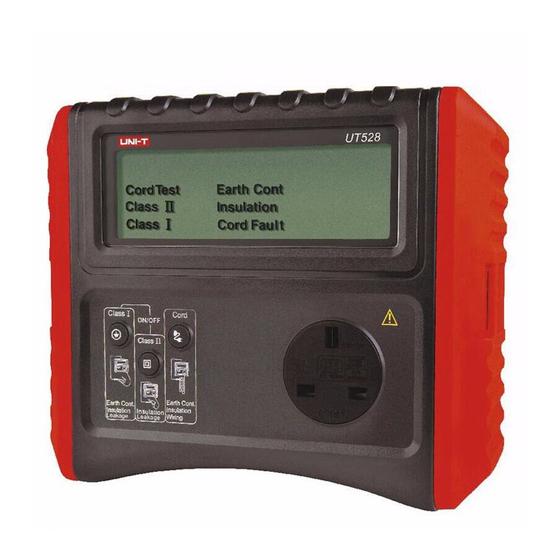
- Page 2 Overview - UT528/528AU UT528/528AU UT528/528AU from. UT528/528AU Main Unit...
- Page 3 Do not use or store the unit in high temperature, humid, flammable or electromagnetic environments as damage and incorrect readings may result. ● If the tester requires repair or replacement please contact your local service center. Declaration of Conformity Uni-T manufactures this product and declares that this product conforms to the...
- Page 4 2013 2010 UT528/528AU...
- Page 5 8.Warning Symbol 9.Unit Error 10.Readings and Cable Results 11.Leakage Current 12.Double Insulated / Class II Test 13.Class I Test...
- Page 6 Class I Test Button + Zero/Null Selection Class II Test Button + 250V/500V Selection IEC / Cable Test Button +30m Long Lead Selection Earth Probe Mains / IEC testing...
- Page 7 Front Panel Operation 1: Press button to Power ON / Power OFF. 2: Press button when testing a CLASS I Appliance. 3: Press button when testing a CLASS II Appliance. 4: Press button when performing Cord / Extension Lead testing. Advance Features 5.
- Page 8 The unit will automatically switch off after approximately 2 minutes if no buttons are pressed. Testing a Class 1 Appliance Plug the appliance into the UT528/528AU panel main socket. Plug the earth test lead into the socket on the UT528/528AU end panel. Connect the earth crocodile clip to an...
- Page 9 exposed metal part on the appliance as shown in Diagram 3. 1. Earth / Protective Conductor Test Press the Class 1 test button to start the test. The earth resistance test will begin.
- Page 10 If the earth resistance measured is greater than the selected PASS limit for earth bond (0.1Ω/0.2Ω/0.3Ω), the meter will display “×Earth Cont”, which is a FAIL. If this occurs, re-check the connections between the pin of the plug to the bodywork of the appliance and that the crocodile clip is attached to clean earthed metalwork on the appliance (try attaching the clip to analternative piece of metalwork).
- Page 11 2. Insulation Resistance Test Before the unit carries out the insulation test it will attempt to check that the connected appliance’s power switch is in the ON position. If it detects that the appliance switch is in the ON position it will automatically carry out the insulation test.
- Page 12 Sub Leak” Sub Leak” as a UT528/528AU UT528/528AU...
- Page 13 Class 2 Pre-Check If the unit detects that the appliance appears to be Class 1 as it detects an earth connection (possibly as a result of a connected earth clip) it will display a flashing symbol and you will be prevented from carrying out the Class 2 test.
- Page 14 see if the appliance is in the ON position. If it detects that the appliance switch is in the OFF position it will wait and display a flashing symbol. If you are sure that the appliance is switched ON press the button again to start the test.
- Page 15 Leakage Test 5. After the unit has completed the insulation test it will automatically proceed to the leakage test.If the measured leakage is less than 5mA, the meter will display “√ Sub Leak” as a PASS rating.If greater than 5mA, it will display “× Sub Leak” as a FAIL rating.
-
Page 16: Insulation Test
To Start the Cord Test Press 1. Earth Bond Test The unit will carry out an earth bond test in the same manner as a Class 1 appliance. The Pass mark for this test is less than the setup value(0.1,0.2,0.3Ω). 2. - Page 17 Note: when testing Surge Protected Extension Leads this test may fail. This is normal and a result of circuitry within the surge protection device. 3. Polarity Test The polarity test is the final test to be carried out and will check that the cord or extension is wired correctly.
- Page 18 into setup mode which can set up the 250V /500V test voltage and 0.1Ω/0.2Ω/0.3Ω earth continuity Pass /Fail value, the button to change Pass /Fail value and the button to change test voltage,and the button to save and turn back. The insulation test voltage reduces from 500V to 250V to allow for the testing of surge protected appliances and leads.
- Page 19 that the socket is wired correctly. Connect an IEC lead to the mains socket and plug this into the back of the meter as shown in Diagram 6. 1)If the Live and Neutral in the socket wiring are reversed or there is a fault with the protective earth connection this is indicated as “LN√, LE×, NE×, FAIL”.
- Page 20 <2mA 1k Leakage Current Accuracy ±(5%+2) Test Voltage 40Vrms,50Hz AC Test Current <5mA 2k Factory Default PASS/Fail Limits Class I Class II Cord UT528 UT528AU UT528 UT528AU UT528 UT528AU Earth Continuity 0.1/0.2/0.3 ohm 0.2 ohm 1 ohm 1.0Mohms 2.0 Mohms 1.0 Mohms...
- Page 21 Remarks (UT528AU Only): Earth Continuity: Class I ≤ the setup value, Cord≤1 Ω is PASS. Insulation Resistance ≥1.0MΩ is PASS. Leakage: Class II ≤5mA is PASS. Cord Size/ Current Rating length 0.5mm /(3A) 1.0mm /(10A) 1.25mm /(13A) 0.20 0.10 0.10 1.00 0.50 0.40...
- Page 23 Manufactured by Uni-T, an ISO9001 company. Distributed by: New Zealand Huddleston Limited www.huddleston.nz info@huddleston.nz (+64) 09 283 0583 Australia Huddleston Australia PTY Limited www.huddleston.com.au info@huddleston.com.au (+61) 08 7077 4600...
Need help?
Do you have a question about the UT528 and is the answer not in the manual?
Questions and answers