Table of Contents
Advertisement
Advertisement
Table of Contents

Related Manuals for UNI-T UT713


Summary of Contents for UNI-T UT713
- Page 1 Model UT713 OPERATING MANUAL...
-
Page 2: Table Of Contents
Model UT713: OPERATING MANUAL TABLE OF CONTENTS TITLE PAGE Introduction Unpacking Inspection Safety Information Turning the Calibrator On Simulating a Thermocouple Measuring a Thermocouple Simulating TC or Source mV Measure TC or mV Cold Terminal Temperature Autocompensation Explanation of International Symbols... -
Page 3: Title Page
Model UT713: OPERATING MANUAL TABLE OF CONTENTS TITLE PAGE Thermocouple Standards and Scales Millivolt Measure and Source General Specifications... -
Page 4: Introduction
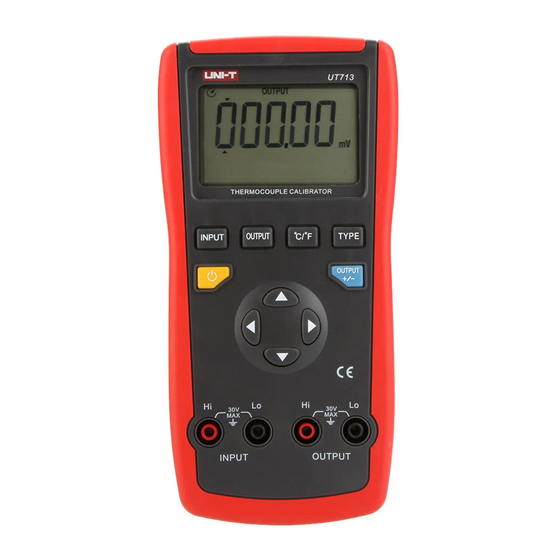
Model UT713: OPERATING MANUAL Introduction The UNI-T Model UT713 Thermocouple Calibrator is a precise source and measurement tool for calibrating thermocouple instruments. The calibrator sources or measures mV or 8 different type of TC in units of . But the Meter cannot uses as an output source and measurement. -
Page 5: Safety Information
Model UT713: OPERATING MANUAL Safety Information This Meter complies with the standard CE EN61326. Use the Meter only as specified in this operating manual, otherwise the protection provided by the Meter may be impaired. Warning To avoid possible electric shock or personal injury: Before using the calibrator inspect the case. - Page 6 Model UT713: OPERATING MANUAL Replace the battery as soon as the battery indicator appears. With a low battery, the Meter might produce false readings that can lead to electric shock and personal injury. The internal circuit of the calibrator shall not be altered at will to avoid...
-
Page 7: Turning The Calibrator On
Model UT713: OPERATING MANUAL Turning the Calibrator On Press to turn the calibrator on and off Output Show TC type or Press to toggle voltage range selected Press so that Press TYPE to OUTPUT is on select TC type or... -
Page 8: Measuring A Thermocouple
Model UT713: OPERATING MANUAL Input Display the Show TC type or selected voltage range elected Press to toggle Press so that INPUT is on the display Press to turn the Meter on and off Press Type to Input Terminals select TC type or... -
Page 9: Simulating Tc Or Source Mv
Model UT713: OPERATING MANUAL 1. Press the pushbutton to turn the Calibrator on. 2. Press OUTPUT to display OUTPUT if the Calibrator is at input mode which displays INPUT. 3. Press to select the requested TC type or DC mV range. - Page 10 Model UT713: OPERATING MANUAL Measurement equipment Figure 3...
-
Page 11: Measure Tc Or Mv
Model UT713: OPERATING MANUAL 1. Press the pushbutton to turn the Calibrator on. 2. Press INPUT to display INPUT if the Calibrator is at output mode which displays OUTPUT. 3. Press to select the requested TC type or DC mV range. - Page 12 Model UT713: OPERATING MANUAL Output equipment Figure 4...
-
Page 13: Cold Terminal Temperature Autocompensation
Model UT713: OPERATING MANUAL Follow the below procedure to start the cold terminal temperature auto compensation functions: 1. Press the pushbutton to turn the Calibrator on. 2. Press INPUT to display enter INPUT mode 3. Press to select J type. - Page 14 Model UT713: OPERATING MANUAL Note: Because the temperature transducer aluminum plate is put at the back of the Calibrator, try to open the tilt stand if possible when operating the Calibrator. Don’t touch the aluminum plate when operating the Calibrator to ensure the accurate of compensation temperature.
-
Page 15: Explanation Of International Symbols
Model UT713: OPERATING MANUAL Explanation of International Symbols The following symbols are used on the calibrator or in this operating manual. The table below explains their meaning. International Symbols Symbol Meaning Grounding Warning. Refer to the Operating Manual Deficiency of Built-In Battery... -
Page 16: Maintenance
Model UT713: OPERATING MANUAL Maintenance Warning Make sure the calibrator is off and the test leads are removed from the input terminals and the circuit under test before opening the calibrator’s case. For maintenance procedures not described in this sheet, contact your dealer. - Page 17 Model UT713: OPERATING MANUAL Periodically wipe the case with a damp cloth and detergent; do not use abrasives or solvents. l When the symbol appears on the display, replace the battery with a 9V alkaline battery (1604A or 6LF22) l Remove the battery from the battery door and turn the calibrator off when it is not using for a long time.
- Page 18 Model UT713: OPERATING MANUAL Warning To avoid personal injury or damage to the calibrator, use only a 125mA 250V fuse for F1. In Input mode, the calibrator and TC are reliably connected. When the display continuisly shows OL, the fuses may be blown.
- Page 19 Model UT713: OPERATING MANUAL Replace the fuses using the following procedure: 1. Remove the test leads from the calibrator terminals and turn the calibrator off. 2. Remove the screw on the battery door, then remove the battery door and take out the battery.
-
Page 20: Specifications
Model UT713: OPERATING MANUAL Specifications Specifications are based on a one year calibration cycle and apply for ambient temperature from +18 to +28 unless stated otherwise. Display Accuracy Thermocouple Temperature Ranges Resolution Type -200.0~1200.0 0.04% 1.5 -328.0~2192.0 ( -100 ) -200.0~1370.0... - Page 21 Model UT713: OPERATING MANUAL Display Accuracy Thermocouple Temperature Ranges Resolution Type 0.04% 3 -20~1750 100 ) -4~3182 0.04% 5.4 -20~1750 212 ) or 1 0.04% 2 -4~3182 100 ) 600~1800 0.04% 3.6 212 ) 1112~3272...
- Page 22 Model UT713: OPERATING MANUAL Thermocouple Type Standard Scales J, K, T, E, N, R, S, B NIST-175 ITS-90 Mode Range Display Resolution Accuracy -10.00~110.00mV 10 V 0.04% 2 digits -110.0~1100.0mV 0.1mV...
- Page 23 Model UT713: OPERATING MANUAL Resolution: TC: 0.1 or 0.1 (J, K, T, E, N); 1 or 1 (R, S, B). DC mV: 10 V (110mV range); 0.1mV (1100mV range) Cold Junction Error: 0.5 (-0~50 ) Maximum voltage applied between any terminal and earth ground or between...
- Page 24 Model UT713: OPERATING MANUAL * END * This operating manual is subject to change without notice.
- Page 25 Model UT713: OPERATING MANUAL Copyright 2007 Uni-Trend Group Limited. All rights reserved. Manufacturer: Uni-Trend Technology (Dongguan) Limited Dong Fang Da Dao Bei Shan Dong Fang Industrial Development District Hu Men Town, Dongguan City Guang Dong Province China Postal Code: 523 925...
Need help?
Do you have a question about the UT713 and is the answer not in the manual?
Questions and answers