Table of Contents
Advertisement
Advertisement
Table of Contents

Related Manuals for UNI-T UT525


Summary of Contents for UNI-T UT525
- Page 1 UT525/526 Electrical Testers Operating Manual...
-
Page 2: Table Of Contents
UT525/526 Operating Manual Contents Item Page I. Safety Precautions II. Features III. Specifications IV. Front View of the Instrument V. Function of Keys and Dial Plate VI. Testing Preparation VII. Earth Testing VIII. RCD Testing IX. Voltage Testing X. Insulation Resistance Testing XI. - Page 3 (RCD), earth, insulation resistance, DCV and ACV; with features of full functions, high accuracy, stable performance, easy and reliable operation, it is available to test RCD, insulation and earth of electric equipments. UT525/ UT526 is the ideal selection for repairing, maintaining and testing RCD of all...
-
Page 4: Safety Precautions
UT525/526 Operating Manual I. Safety Precautions This instrument was designed, manufactured and tested according to IEC61010 safety standard (Safety Requirements for Electrical Equipment). This Instructions describe the warnings and safety rules which ensure the safe operation and safe state of the instrument, which the user must follow. Please read following instructions before using. - Page 5 UT525/526 Operating Manual It means under some conditions, the operation may cause Danger serious or fatal damages may be caused. Warning It means taking care to keep away from electric shock. It means avoiding instrument damage and gain accurate Note testing.
- Page 6 UT525/526 Operating Manual ● Operate carefully under the voltage over 33Vrms, 46.7Vacrms or 70Vdc, electric shock may be caused under such kind of voltage during operating. ● After completing high resistance testing, the charge storage of the circuit to be tested must be released.
- Page 7 UT525/526 Operating Manual ● Do not put or use the instrument in the place with high temperature, high humidity, inflammable or explosive matters and high electromagnetic field. ● Do not clean the cover of the instrument with wet cloth of detergent, do not use abrasives or solvent.
-
Page 8: Features
UT525/526 Operating Manual II. Features Danger of electric shock may happen The instrument has double-insulation or reinforced insulation Earth ● Designed and manufactured strictly according to IEC61010 safety standard, the instrument meets with Over Voltage Standard (CATIII600V) and safety standard of Class II Pollution. -
Page 9: Specifications
UT525/526 Operating Manual III. Specifications Error limit: ±(a% reading + digits), one year of warranty period Environment temperature: 23±5℃ Environment humidity: 45-75%RH UT525/UT526 RCD testing indexes RCD testing current 10mA 30mA 100mA 300mA Applied voltage Voltage: 220V±10%, frequency: 45Hz-65Hz Accuracy tolerance RCD testing current accuracy tolerance with AC (220V±2): (0+10%) - Page 10 UT525/526 Operating Manual UT525 earth testing indexes Rated voltage About 5.0V Test range 0.01Ω-200Ω Test current >200mA for 0.00Ω-2.00Ω Accuracy tolerance 0.01Ω-200Ω: ±(2%+5) UT526 earth testing indexes Rated voltage About 5.0V Test range 0.01Ω-2,000Ω Test current >200mA within 0.00Ω-2.00Ω Accuracy tolerance...
- Page 11 UT525/526 Operating Manual UT525 insulation resistance testing indexes Rated voltage 100V 250V 500V Test range 0.05MΩ-200MΩ Open circuit voltage DC 100V±10% DC 250V±10% DC 500V±10% Rated test current 100KΩ load 250KΩ load 500KΩ load 0.9mA-1.1mA 0.9mA-1.1mA 0.9mA-1.1mA Short circuit <1.8mA Accuracy tolerance 0.05MΩ-200MΩ: ±(5%+5)
- Page 12 UT525/526 Operating Manual UT526 insulation resistance testing indexes Rated voltage 250V 500V 1,000V Test range 0.05MΩ-200MΩ 0.05MΩ-300MΩ 0.05MΩ-500MΩ Open circuit voltage DC 250V±10% DC 500V±10% DC 1,000V±10% Rated test current 500KΩ load 1MΩ load 250KΩ load 0.9mA-1.1mA 0.9mA-1.1mA 0.9mA-1.1mA Short circuit <1.8mA...
- Page 13 UT525/526 Operating Manual UT525/UT526 voltage testing indexes Test range ±0-±440V 0-440 (50/60Hz), just for reference to that less than 10V Resolution ±(2%+3) Accuracy tolerance UT525/UT526 frequency testing indexes Test range 20Hz-100Hz Resolution Accuracy tolerance Just for reference...
- Page 14 UT525/526 Operating Manual ● Display: LCD display, max reading: 9999 ● Low battery voltage warning: ● Over limit indication: “OL” ● Auto range function ● Unit display: can display function, electric unit signs ● Work conditions: 0℃-40℃/ 85%RH or less ●...
-
Page 15: Front View Of The Instrument
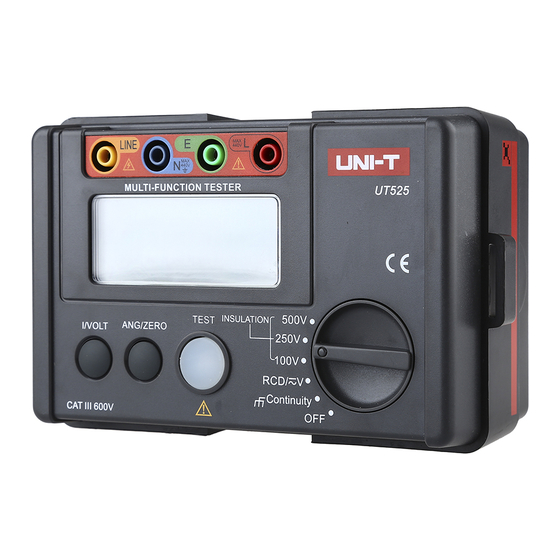
UT525/526 Operating Manual IV. Front View of the Instrument (see Picture 1) 1. L: jack of live wire terminal for RCD testing and positive terminal for voltage testing 2. E: jack of earth for RCD testing 3. N: jack of null wire terminal for RCD testing and input negative terminal for voltage testing 4. - Page 16 UT525/526 Operating Manual Picture 1...
-
Page 17: Function Of Keys And Dial Plate
5. When dial plate points to RCD/V, enter RCD testing and AC and DC voltage testing; 6. When dial plate points to UT525 output voltage: 100V/250V/500V or UT526 output voltage: 250V/500V/1,000V (select the demanded output voltage) respectively, enter insulation resistance testing;... -
Page 18: Earth Testing
UT525/526 Operating Manual VII. Earth Testing (see Picture 2 for the connection diagram ) Connect the object to be tested with the instrument according to the diagram, after that make the dial plate point to Continuly, and then press TEST key to start earth test. - Page 19 UT525/526 Operating Manual Picture 2...
-
Page 20: Rcd Testing
UT525/526 Operating Manual VIII. RCD Testing (see Picture 3 for the connection diagram) Make the dial plate point to RCD/V and press I/VOLT key to set up test current (test current: 10mA\30mA\100mA\300mA) to start RCD testing. Connection Method: Connect the red, green and blue testing wires of three-wire plug with the red (L), green (E) and blue (N) ports respectively, and then insert the three-wire plug into the 220V civil jack and press TEST key. - Page 21 UT525/526 Operating Manual Picture 3...
-
Page 22: Voltage Testing
UT525/526 Operating Manual IX Voltage Testing (see Picture 4 for the connection diagram) Make the dial plate point to RCD/V and the long press I/VOLT key to switch to AC, DC voltage testing state: Connection method 1: (1) Insert red testing wire into “L” input port, and black testing wire into “N”... - Page 23 UT525/526 Operating Manual Note 1. Do not input voltage over 440V or 440Vrms. It is possible to display higher voltage, but the instrument may be damaged. 2. During testing high voltage, especially avoid electric shock. 3. After completing all the testing, cut the connection between testing wires and the circuit tested, and dismantle the testing wires from input terminal of the instrument.
- Page 24 UT525/526 Operating Manual Picture 4...
-
Page 25: Insulation Resistance Testing
3. Do not make the two pens short circuit state under high voltage input and do not test the insulation resistance after outputting high voltage. Press to make the dial plate point to UT525 (100V/250V/500V) or UT526 (250V/500V/1,000V) 1. Before testing insulation resistance, the circuit to be tested must be discharged completely and separated from the power circuit absolutely. - Page 26 UT525/526 Operating Manual Continuous Testing Operation Select one test voltage with dial plate (the optional voltages of UT525: 100V/250V/500V; the optional voltages of UT526: 250V/500V/1,000V) and press TEST key which is in self-locking state to make continuous testing and output insulation resistance testing voltage, and the test light become red. After completing testing, press TEST key to unlock to stop testing.
- Page 27 UT525/526 Operating Manual Picture 5...
-
Page 28: Replace Battery
UT525/526 Operating Manual XI. Replace Battery (see Picture 6) Note 1. Do not use old and new batteries at the same time. 2. Pay attention to the polarity during replacing battery. Danger 1. To avoid potential electric shock, move the lead from the instrument before replacing battery. - Page 29 UT525/526 Operating Manual Picture 6...
-
Page 30: Maintenance
UT525/526 Operating Manual XII. Maintenance Clear the shell ● Wipe the surface with soft wet cloth or sponge. ● To avoid instrument damage, do not dip the instrument into water. ● When the instrument is wet, make it dry and then store.
Need help?
Do you have a question about the UT525 and is the answer not in the manual?
Questions and answers