
Related Manuals for UNI-T UT90C


Summary of Contents for UNI-T UT90C
-
Page 1: Table Of Contents
Model UT90C: OPERATING MANUAL Table of Contents Title Page Overview Unpacking Inspection Safety Information Rules For Safe Operation International Electrical Symbols The Meter Structure Rotary Switch Functional Buttons Display Symbols Measurement Operation A. AC & DC Voltage Measurement B. Measuring Resistance, Diodes, Continuity &... -
Page 2: Title Page
Model UT90C: OPERATING MANUAL Title Page Maintenance A. General Service B. Replacing the Fuses... -
Page 3: Overview
To avoid electric shock or personal injury, read the “Safety Information” and “Rules for Safe Operation” carefully before using the Meter. The Model UT90C (hereafter referred to as “the Meter”) is a 4000 counts, 3 3/4 digits environment protected auto ranging electrical tester with stabilized functions, safe design, and reliable performance. -
Page 4: Unpacking Inspection
Model UT90C: OPERATING MANUAL Unpacking Inspection Open the package case and take out the Meter. Check the following items carefully to see any missing or damaged part: Item Description 1 piece English Operating Manual Test Lead 1 pair Holster 1 piece In the event you find any missing or damage, please contact your dealer immediately. -
Page 5: Safety Information
Model UT90C: OPERATING MANUAL Safety Information Safety Information This Meter complies with standards IEC61010: in pollution degree 2, overvoltage category (CAT. II 1000V, CAT. III 600V) and double insulation. Use the Meter only as specified in this operating manual, otherwise the protection provided by the Meter may be impaired. -
Page 6: Rules For Safe Operation
Model UT90C: OPERATING MANUAL Rules For Safe Operation (1) To avoid possible electric shock or personal injury, and to avoid possible damage to the Meter or to the equipment under test, adhere to the following rules: l Before using the Meter inspect the case. Do not use the Meter if it is damaged or the case (or part of the case) is removed. - Page 7 Model UT90C: OPERATING MANUAL Rules For Safe Operation (2) produce false readings that can lead to electric shock and personal injury. l When servicing the Meter, use only the same model number or identical electrical specifications replacement parts. l The internal circuit of the Meter shall not be altered at will to avoid damage of the Meter and any accident.
-
Page 8: International Electrical Symbols
Model UT90C: OPERATING MANUAL International Electrical Symbols AC (Alternating Current). DC (Direct Current). AC or DC. Grounding. Double Insulated. Deficiency of Built-In Battery. Continuity Test. Diode. Capacitance Test Fuse. Warning. Refer to the Operating Manual. Conforms to Standards of European Union. -
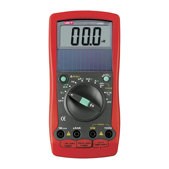
Page 9: The Meter Structure
Model UT90C: OPERATING MANUAL The Meter Structure (see figure 1) ( figure 1) 1 LCD Display. 2 Solar Panel. 3 SELECT Button. 4 Rotary Switch. 5 HOLD Button. 6 Input Terminals 7 Relative Mode & RESET Button... -
Page 10: Rotary Switch
Model UT90C: OPERATING MANUAL Rotary Switch Below table indicated for information about the rotary switch positions. Rotary Function Switch Position Power is turned off. AC/DC voltage measurement. : Diode test. : Continuity test. : Capacitance test. : Resistance measurement. Frequency Test. -
Page 11: Functional Buttons
Model UT90C: OPERATING MANUAL Functional Buttons Below table indicated for information about the functional button operations. Button Measuring Operation Function Performed Press RESET to enter Any rotary RESET and exit the mode in any switch position measuring mode except in... -
Page 12: Display Symbols
Model UT90C: OPERATING MANUAL Display Symbols(1) (see figure 2) ( figure 2) Symbol Meaning Indicator for AC voltage or current. The displayed value is the mean value. Indicates negative reading. Charge indicator. CHARGE The Meter is in the auto range... - Page 13 Model UT90C: OPERATING MANUAL Display Symbols(2) (see figure 2) Symbol Meaning The continuity buzzer is on. Test of diode. Ohm. The unit of resistance. ,k ,M kilohm.1 x 10 or 1000 ohms. Megaohm. 1 x 10 1,000,000 ohms. Farad. The unit of capacitance.
-
Page 14: Measurement Operation
Model UT90C: OPERATING MANUAL Measurement Operation(1) DC & AC Voltage Measurement (see figure 3) black ( figure 3) Warning To avoid harms to you or damages to the Meter from electric shock, please do not attempt to measure voltages higher than 1000VDC / 750VAC RMS although readings may be obtained. - Page 15 Model UT90C: OPERATING MANUAL Measurement Operation(2) Note l At 400mV range, the Meter has an input impedance of 4000M All other ranges the Meter has an input impedance of 10M This loading effect can cause measurement errors in high impedance circuits. If the circuit impedance is less than or equal to 10k the error is negligible (0.1% or less).
-
Page 16: Continuity & Capacitance
Model UT90C: OPERATING MANUAL Measurement Operation(3) B.Measuring Resistance, Diodes, Continuity & Capacitance Warning To avoid harms to you, never attempt to input over 60V in DC or 30V rms in AC. To avoid damages to the Meter or to the devices... - Page 17 Model UT90C: OPERATING MANUAL Measurement Operation(4) 2. Set the rotary switch to resistance measurement ( ) is defaults or press SELECT button to select measurement mode. 3. Connect the test leads across with the object being measured. The measured value shows on the display.
- Page 18 Model UT90C: OPERATING MANUAL Measurement Operation(5) Testing Diodes (see figure 5) black ( figure 5) Use the diode test to check diodes, transistors, and other semiconductor devices. The diode test sends a current through the semiconductor junction, and then measures the voltage drop across the junction.
- Page 19 Model UT90C: OPERATING MANUAL Measurement Operation(6) l Connect the test leads to the proper terminals as said above to avoid error display. The LCD will display OL indicating open-circuit for wrong connection. The unit of diode is Volt (V), displaying the positive- connection voltage-drop value.
- Page 20 Model UT90C: OPERATING MANUAL Measurement Operation(7) l When continuity testing has been completed, disconnect the connection between the testing leads and the circuit under test. Capacitance Measurement (see figure 7) black ( figure 7) The Meter’s capacitance ranges are: 40.00nF, 400.0nF, 4.000µF, 40.00µF, and 100.0µF.
-
Page 21: Frequency Measurement
Model UT90C: OPERATING MANUAL Measurement Operation(8) l For testing the capacitor with polarity, connect the red test lead to anode & black test lead to cathode instead of using test leads as mentioned above. l It takes a longer time when testing a capacitor value which is higher than 10µF range. -
Page 22: Ac & Dc Current Measurement
Model UT90C: OPERATING MANUAL Measurement Operation(9) Note l When Hz measurement has been completed, disconnect the connection between the testing leads and the circuit under test. D.AC & DC Current Measurement (see figure 9) black red ( figure 8) Warning... - Page 23 Model UT90C: OPERATING MANUAL Measurement Operation(10) To measure current, do the following: 1. Turn off power to the circuit. Discharge all high- voltage capacitors. 2. Insert the red test lead into the AmA or 10A terminal and the black test lead into the COM terminal.
-
Page 24: Power Charging
Model UT90C: OPERATING MANUAL Measurement Operation(11) E.Power Charging (see figure 10) black ( figure 10) Warning Start charging as soon as the power indicator appears. With a low battery, the Meter might produce false readings that can lead to electric shock and personal injury. - Page 25 Model UT90C: OPERATING MANUAL Measurement Operation(11) l Charge at 12-36V 1. Insert the red test lead into the HzV erminal and the black test lead into the COM terminal. 2. Set the rotary switch to 12-36V 3. Place the test leads’ probe tip onto the 12-36V power supply respectively.
-
Page 26: Operation Of Hold Mode
Model UT90C: OPERATING MANUAL Operation of Hold Mode Warning To avoid possibility of electric shock, do not use Hold mode to determine if circuits are without power. The Hold mode will not capture unstable or noisy readings. The Hold mode is applicable to all measurement functions. -
Page 29: General Specifications
Model UT90C: OPERATING MANUAL General Specifications(2) l Safety/Compliances : IEC61010: CAT. II 1000V, CAT. III 600V overvoltage and double insulation standard. l Certification... -
Page 30: Accuracy Specifications
Model UT90C: OPERATING MANUAL Accuracy Specification(1) Accuracy: (a% reading + b digits),guarantee for 1 year. Operating temperature:23 Relative humidity:<75%. Temperature coefficient: 0.1 x (specified accuracy) / 1 A.AC Voltage Overload Accuracy Range Resolution Protection 1000V DC 10mV (1%+5) or 750V AC... -
Page 31: Resistance
Model UT90C: OPERATING MANUAL Accuracy Specification(2) C. Resistance Overload Accuracy Range Resolution Protection (1.2%+2) (1%+2) 600Vp 400k (1.2%+2) (1.5%+2) Remarks: l Open circuit voltage: approx. 0.45V D. Diode & Continuity Range Resolution Overload Protection 600Vp E. Capacitance Test Overload Accuracy... -
Page 34: Maintenance
Model UT90C: OPERATING MANUAL Maintenance(1) This section provides basic maintenance information including battery and fuse replacement instruction. Warning Do not attempt to repair or service your Meter unless you are qualified to do so and have the relevant calibration, performance test, and service information. - Page 35 Model UT90C: OPERATING MANUAL Maintenance(2) Warning To avoid electrical shock or arc blast, or personal injury or damage to the Meter, use specified fuses ONLY in accordance with the following procedure. Replacement of the fuses is seldom required. Burning of a fuse always results from improper operation.
- Page 36 Model UT90C: OPERATING MANUAL Copyright 2001 Uni-Trend International Limited. All rights reserved. Manufacturer: UNI-TREND TECHNOLOGY(DONG GUAN)LIMITED Address: Dong Fang Da Dao, Bei Shan Dong Fang Industrial Development District, Hu Men Town, Dong Guan City, Guang Dong Province, China Headquarters: Uni-Trend International Limited...
Need help?
Do you have a question about the UT90C and is the answer not in the manual?
Questions and answers