Table of Contents
Advertisement
Advertisement
Table of Contents

Subscribe to Our Youtube Channel
Related Manuals for ATEN Master View CL-1758


Summary of Contents for ATEN Master View CL-1758
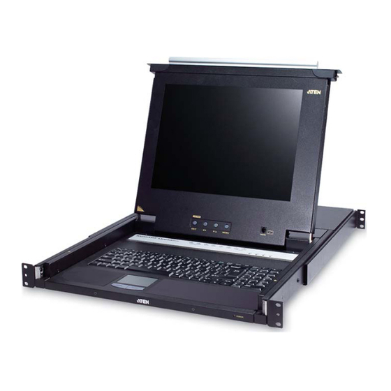
- Page 1 Master View Max Slideaway™ LCD KVM Switch CL-1758 User Manual www.aten.com...
-
Page 2: Fcc Information
CL-1758 User Manual FCC Information This is an FCC Class A product. In a domestic environment this product may cause radio interference in which case the user may be required to take adequate measures. This equipment has been tested and found to comply with the limits for a Class A digital device, pursuant to Part 15 of the FCC Rules. -
Page 3: User Information
CL-1758 User Manual User Information Online Registration Be sure to register your product at our online support center: International http://support.aten.com North America ATEN TECH http://www.aten-usa.com/product_registration ATEN NJ http://support.aten.com Telephone Support For telephone support, call this number: International 886-2-8692-6959 North America... -
Page 4: Package Contents
© Copyright 2007 ATEN® International Co., Ltd. Manual Part No. PAPE-0250-200G Printing Date: 11/2007 ATEN and the ATEN logo are registered trademarks of ATEN International Co., Ltd. All rights reserved. All other brand names and trademarks are the registered property of their respective owners. -
Page 5: Table Of Contents
CL-1758 User Manual Contents FCC Information ..........ii RoHS. - Page 6 CL-1758 User Manual OSD ..........24 Hotkey .
- Page 7 CL-1758 User Manual 8. Appendix Safety Instructions......... . . 59 General .
-
Page 8: About This Manual
PC to Sun keyboard emulation mappings. Chapter 7, The Firmware Upgrade Utility, explains how to use this utility to upgrade the CL-1758's firmware with the latest available versions. An Appendix, provides specifications and other technical information regarding the CL-1758. -
Page 9: Conventions
For information about all ATEN products and how they can help you connect without limits, visit ATEN on the Web or contact an ATEN Authorized Reseller. Visit ATEN on the Web for a list of locations and telephone numbers: International http://www.aten.com... - Page 10 CL-1758 User Manual This Page Intentionally Left Blank...
-
Page 11: Introduction
Chapter 1 Introduction Overview The Master View CL-1758 KVM Switch is a control unit that allows access to multiple computers from a single keyboard, monitor, and mouse (KVM) console. Before the development of the Master View, the only way to control multiple computer configurations from a single console was through a complex and costly network system. - Page 12 Since the CL-1758 intercepts keyboard input directly, it works on multiple operating platforms (PC compatible, Mac*, Sun*, etc.). There is no better way to save time and money than with a CL-1758 installation. Since a single console manages all of the computers, the CL-1758 setup: (1) eliminates the expense of having to purchase a separate keyboard, monitor, and mouse for each computer;...
-
Page 13: Features
Chapter 1. Introduction Features Integrated KVM console with 15"or 17" LCD monitor in a Slideaway™ housing. Slideaway™ housing is less than 1 U – with top and bottom clearance for smooth operation in a 1U high system rack. Space saving technology - two consoles (one bus) controls 8 computers. Cascadable to three levels for control of up to 512 computers from a single console. -
Page 14: Hardware Requirements
Either a Type A USB port, or PS/2 keyboard and mouse ports (see the Cables discussion in the next section). Cables Only the following ATEN Custom KVM cable sets may be used with these switches. Depending on the KVM cable type, the switches can link to computers that use PS/2 connectors to transfer keyboard and mouse data as well as computers that use USB connectors (see the installation diagram on p. -
Page 15: Components
Chapter 1. Introduction Components Front View 4 & 5 10 & 11 (Continues on next page.) - Page 16 Firmware Upgrade Port: The Firmware Upgrade Cable Upgrade Section that transfers the firmware upgrade data from the adminis- trator's computer to the CL-1758 plugs into this RJ-11 con- nector. Firmware Upgrade Switch: During normal operation this switch should be in the NORMAL position. (See p. 51 for firmware upgrading details.)
-
Page 17: Rear View
This is a standard 3 prong AC power socket. The power cord from an AC source plugs in here. Power Switch External For flexibility and convenience, the CL-1758 supports an Console Section independent, external, KVM console. The external console's keyboard, monitor, and mouse cables plug in here. - Page 18 CL-1758 User Manual This Page Intentionally Left Blank...
-
Page 19: Hardware Setup
Chapter 2 Hardware Setup Before You Begin 1. Important safety information regarding the placement of this device is provided on page 59. Please review it before proceeding. 2. Make sure that the power to any device that you connect to the installation has been turned off. -
Page 20: Standard Rack Mounting
CL-1758 User Manual Standard Rack Mounting A standard rack mounting kit is provided with your CL-1758. The kit enables the switch to be mounted in rack with a depth of 42.0 - 82.0 cm. L Brackets Side Mountng Brackets Note: It takes two people to mount the switch: one to hold it in place; the other to screw it in. - Page 21 Chapter 2. Hardware Setup To rack mount the switch, do the following: 1. While one person positions the switch in the rack and holds it in place, the second person - using the screws provided with the rack mounting kit - loosely screws the front brackets to the rack.
-
Page 22: Single Stage Installation
This completes the single stage installation, and you can power on the switch. After the switch has been powered on, you can turn on the power to the computers. Note: The CL-1758 initially links to the first port when you turn it on. -
Page 23: Single Stage Installation Diagram
Chapter 2. Hardware Setup Single Stage Installation Diagram USB Connection PS/2 Connection... -
Page 24: Two Stage Installation
3. Using a KVM cable set (see Cables, page 4), plug the custom SPHD connector into any available KVM Port on the switch. Note: The CL-1758 does not support the audio features of audio enabled KVM switches. 4. At the other end of the cable: a) For a USB connection (see p. -
Page 25: Two Stage Installation Diagram
Chapter 2. Hardware Setup Two Stage Installation Diagram CL-1758 CS-1758 F/W UPGRADE NORMAL RECOVER Note: The Power On sequence requires that all Second Stage units be powered on first. After all the Second Stage units have been powered on, then the First Stage unit must be powered on next. -
Page 26: Three Stage Installation
CL-1758 User Manual Three Stage Installation The procedures for setting up a three stage installation are essentially the same as for a two stage installation. With a three stage setup, as many as 512 computers can be controlled in a complete installation. A table showing the relation between the number of computers and the number of switches needed to control them is provided on page 64. -
Page 27: Three Stage Installation Diagram
Chapter 2. Hardware Setup Three Stage Installation Diagram CL-1758 CS-1758 F/W UPGRADE NORMAL RECOVER CS-1758 F/W UPGRADE NORMAL RECOVER... - Page 28 CL-1758 User Manual This Page Intentionally Left Blank...
-
Page 29: Basic Operation
Chapter 3 Basic Operation Opening the Console The CL-1758's console is located under the top cover. To access the console, slide the console module out and raise the cover. Note: As a safety precaution, to keep the console from accidentally sliding out, the console is locked into the In position. -
Page 30: Closing The Console
CL-1758 User Manual Closing the Console To slide the console module back in, close the cover and do the following: 1. Pull the safety catches on the unit's side rails toward you and push the module in until it stops. -
Page 31: Operating Precautions
Chapter 3. Basic Operation Operating Precautions The maximum load bearing capacity of the keyboard module is 30kg. Failure to heed the information below can result in damage to the keyboard module. Right! Rest your hands and arms lightly on the keyboard module as you work. -
Page 32: Lcd Osd Configuration
CL-1758 User Manual LCD OSD Configuration The LCD Buttons The LCD OSD allows you to set up and configure the LCD display. Four buttons are used to perform the configuration, as described in the table, below: Button Function MENU When you have not entered the LCD OSD Menu function, pressing this button invokes the Menu function, and brings up the Main Menu. -
Page 33: The Adjustment Settings
Chapter 3. Basic Operation The Adjustment Settings An explanation of the LCD OSD adjustment settings is given in the table below: Setting Explanation Brightness Adjusts the background black level of the screen image. Contrast Adjusts the foreground white level of the screen image. Phase Adjusts the vertical size of the screen image. -
Page 34: Port Selection
Manual, On Screen Display (OSD), and Hotkey. Manual For manual port selection on the CL-1758, simply press the Port Switch that corresponds to the device you wish to access. For manual port selection on the cascaded CS-1758 switches, first press the... -
Page 35: Hot Plugging
Chapter 3. Basic Operation Hot Plugging The CL-1758 supports hot plugging - components can be removed and added back into the installation by unplugging their cables from the ports without the need to shut the unit down. In order for hot plugging to work properly, however, the procedures described below must be followed. -
Page 36: Powering Off And Restarting
CL-1758 User Manual Powering Off and Restarting If it becomes necessary to Power Off one of the switches, you must do the following before starting it back up: 1. Shut down all the computers that are attached to it. If there are switches cascaded down from it, all the cascaded switches and the computers attached to them must be shut down, as well. -
Page 37: Port Id Numbering
Chapter 3. Basic Operation Port ID Numbering Each KVM port on a Master View installation is assigned a unique Port ID. You can directly access any computer on any level of the installation by specifying the Port ID of the KVM port that the computer is connected to - either with the OSD (see page 29), or with the Hotkey port selection method (see page 41). - Page 38 CL-1758 User Manual This Page Intentionally Left Blank...
-
Page 39: Osd Operation
Chapter 4 OSD Operation OSD Overview The On Screen Display (OSD) is a menu driven method to handle computer control and switching operations. All procedures start from the OSD Main Screen. To pop up the Main Screen, tap the OSD key (see p. 71), or tap the [Scroll Lock] key twice. - Page 40 CL-1758 User Manual When you invoke the OSD, a screen similar to the one below appears: F1:GOTO F3:SET F7:SCAN X F8:LOUT z z z F2:LIST F4:ADM ADMINISTRATOR LIST:ALL NAME 1 - 6 - 6 ATEN INTL. 1 1 - 6 - 7 ATEN INTL.
-
Page 41: Osd Navigation
Chapter 4. OSD Operation OSD Navigation To dismiss the menu, and deactivate the OSD, Click the X at the upper right corner of the OSD Window; or press [Esc]. To Logout, Click F8 or the symbol at the top of the Main Screen, or press [F8]. -
Page 42: Osd Functions
CL-1758 User Manual OSD Functions OSD functions are used to configure and control the OSD. For example, you can: rapidly switch to any port; scan selected ports only; limit the list you wish to view; designate a port as a Quick View Port; create or edit a port name; or make OSD setting adjustments. -
Page 43: F2 List
Chapter 4. OSD Operation F2 LIST Many of the OSD functions only operate on the computers that are listed on the Main Screen. This function lets you broaden or narrow the scope of which ports the OSD displays (lists) on the Main Screen. The submenu choices and their meanings are given in the table below: Choice Meaning... -
Page 44: F3 Set
CL-1758 User Manual F3 SET This function allows the Administrator and each User to set up their own, individual, working environment. A separate profile for each is stored by the OSD and is activated according to the Username provided during Login. - Page 45 Chapter 4. OSD Operation (Continued from previous page.) Setting Function PORT ID Selects how the Port ID is displayed: the Port Number alone DISPLAY (PORT NUMBER); the Port Name alone (PORT NAME); or the MODE Port Number plus the Port Name (PORT NUMBER + PORT NAME).
-
Page 46: F4 Adm
CL-1758 User Manual F4 ADM F4 is an Administrator only function. It allows the Administrator to configure and control the overall operation of the OSD. To change a setting Double Click it; or use the Up and Down Arrow Keys to move the highlight bar to it then press [Enter]. - Page 47 Chapter 4. OSD Operation (Continued from previous page.) Setting Function EDIT PORT To help remember which computer is attached to a particular port, NAMES every port can be given a name. This function allows the Administrator to create, modify, or delete port names. To Edit a port name: 1.
- Page 48 CL-1758 User Manual (Continued from previous page.) Setting Function SET QUICK This function lets the Administrator select which Ports to include as VIEW PORTS Quick View ports. Note: Only the ports currently chosen for the LIST view on the OSD Main Screen (see F2 LIST, page 33), show up here.
-
Page 49: F7 Scan
Chapter 4. OSD Operation F7 SCAN This function automatically switches among the available computers at regular intervals so that you can monitor their activity without having to take the trouble of switching manually. The selection of computers to be included for Auto Scanning is made with the Scan Mode setting under the F3 SET function (see p. - Page 50 CL-1758 User Manual This Page Intentionally Left Blank...
-
Page 51: Keyboard Port Operation
Chapter 5 Keyboard Port Operation The CL-1758 provides an extensive, easy-to-use, hotkey function that makes it convenient to control and configure your KVM installation from the keyboard. Note: The hotkey function must be enabled to use hotkey operations. See HOTKEY COMMAND MODE, page 35, for details. -
Page 52: Hotkey Port Access
Auto Scan Mode Selecting the Active Port Each KVM port on the CL-1758 installation is assigned a unique Port ID (see Port ID Numbering, page 27). You can bring the KVM focus to any computer on the installation with a Hotkey combination that specifies the Port ID of the KVM Port that it is connected to. -
Page 53: Auto Scanning
Auto Scanning Auto Scanning allows the automatic monitoring of computer activity instead of having to switch manually. Invoking Auto Scan Mode causes the CL-1758 to switch the KVM focus among all the active KVM Ports that are accessible to the currently logged on user at regular intervals. (See SCAN MODE, page 35, for information regarding accessible ports.) -
Page 54: Hotkey Configuration
CL-1758 User Manual Hotkey Configuration Hotkeys can also be used to set up the CL-1758's working environment, as shown in the sections that follow. Alternate Hotkey Invocation Keys An alternate set of hotkey invocation keys is provided in case the default set conflicts with programs running on the computers. -
Page 55: Keyboard Operating Platform
Chapter 5. Keyboard Port Operation Keyboard Operating Platform The CL-1758's default port configuration is for a PC Compatible keyboard operating platform. If you have a Mac or a Sun on your installation, you can change its port's keyboard operating platform as follow: 1. -
Page 56: Beeper Control
Beeper Off for one second; then the message disappears and you automatically exit Hotkey Mode. Restore Default Settings To reset the CL-1758 to its default hotkey settings, do the following: 1. Invoke HKM (see p. 41). 2. Press [R] [Enter]. -
Page 57: Hotkey Summary Table
Chapter 5. Keyboard Port Operation Hotkey Summary Table [Num Lock] + [-] [Port ID] [Enter] Switches the KVM focus to the computer that corresponds to that Port ID [Ctrl] + [F12] Invokes Auto Scan Mode. When Auto Scan Mode is in effect, [P] or Left Click pauses Auto Scanning. - Page 58 CL-1758 User Manual This Page Intentionally Left Blank...
-
Page 59: Keyboard Emulation
Chapter 6 Keyboard Emulation Mac Keyboard The PC compatible (101/104 key) keyboard can emulate the functions of the Mac keyboard. The emulation mappings are listed in the table below. PC Keyboard Mac Keyboard [Shift] Shift [Ctrl] Ctrl [Ctrl] [1] [Ctrl] [2] [Ctrl] [3] [Ctrl] [4] [Alt]... -
Page 60: Sun Keyboard
CL-1758 User Manual Sun Keyboard The PC compatible (101/104 key) keyboard can emulate the functions of the Sun keyboard when the Control key [Ctrl] is used in conjunction with other keys. The corresponding functions are shown in the table below. -
Page 61: The Firmware Upgrade Utility
Chapter 7 The Firmware Upgrade Utility The Windows-based Firmware Upgrade Utility (FWUpgrade.exe) provides a smooth, automated process for upgrading the KVM switch's firmware. The Utility comes as part of a Firmware Upgrade Package that is specific for each device. New firmware upgrade packages are posted on our web site as new firmware revisions become available. -
Page 62: Preparation
CL-1758 User Manual Preparation To prepare for the firmware upgrade, do the following: 1. From a computer that is not part of your KVM installation go to our Internet support site and choose the model name that relates to your device to get a list of available Firmware Upgrade Packages. -
Page 63: Starting The Upgrade
Chapter 7. The Firmware Upgrade Utility Starting the Upgrade To upgrade your firmware: 1. Run the downloaded Firmware Upgrade Package file - either by double clicking the file icon, or by opening a command line and entering the full path to it. The Firmware Upgrade Utility Welcome screen appears: Note: The screens shown in this section are for reference only. - Page 64 CL-1758 User Manual (Continued from previous page.) 3. Click Next to continue. The Firmware Upgrade Utility main screen appears. The devices capable of being upgraded are listed in the Device List panel: 4. As you select devices, a detailed description of each appears in the Device...
- Page 65 Chapter 7. The Firmware Upgrade Utility 5. After you have made your device selection(s), Click Next to perform the upgrade. If you enabled Check Firmware Version, the Utility compares the device's firmware level with that of the upgrade files. If it finds that the device's version is higher than the upgrade version, it brings up a dialog box informing you of the situation and gives you the option to Continue or Cancel.
-
Page 66: Upgrade Succeeded
CL-1758 User Manual Upgrade Succeeded After the upgrade has completed, a screen appears to inform you that the procedure was successful: Click Finish to close the Firmware Upgrade Utility. Upgrade Failed If the Upgrade Succeeded screen doesn't appear, it means that the upgrade failed to complete successfully. -
Page 67: Firmware Upgrade Recovery
Chapter 7. The Firmware Upgrade Utility Firmware Upgrade Recovery There are basically three conditions that call for firmware upgrade recovery: When you invoke Firmware Upgrade Mode (see Preparation, page 52), but decide not to proceed with the upgrade. When the Mainboard firmware upgrade fails. When the I/O firmware upgrade fails. - Page 68 CL-1758 User Manual This Page Intentionally Left Blank...
-
Page 69: Appendix
Appendix Safety Instructions General Read all of these instructions. Save them for future reference. Follow all warnings and instructions marked on the device. Do not place the device on any unstable surface (cart, stand, table, etc.). If the device falls, serious damage will result. Do not use the device near water. - Page 70 CL-1758 User Manual (Continued from previous page.) If an extension cord is used with this device make sure that the total of the ampere ratings of all products used on this cord does not exceed the extension cord ampere rating. Make sure that the total of all products plugged into the wall outlet does not exceed 15 amperes.
-
Page 71: Rack Mounting
Appendix Rack Mounting Before working on the rack, make sure that the stabilizers are secured to the rack, extended to the floor, and that the full weight of the rack rests on the floor. Install front and side stabilizers on a single rack or front stabilizers for joined multiple racks before working on the rack. -
Page 72: Technical Support
CL-1758 User Manual Technical Support Technical support is available both by email and online (with a browser over the web): International Email Support support@aten.com Online Technical Support http://support.aten.com Support Troubleshooting http://www.aten.com Documentation Software Updates Telephone Support 886-2-8692-6959 North America Email Support ATEN TECH support@aten-usa.com... -
Page 73: Specifications
Appendix Specifications Function CL1758 Computer Connections Direct Max. 512 (via Cascade CS1758) Port Selection OSD, Hotkey, Pushbutton Second Keyboard 1 x 6 Pin Mini-Din Female (Purple) Console Ports Video 1 x HDB-15 Female (Blue) Mouse 1 x 6 Pin Mini-Din Female (Green) Connectors KVM Ports Keyboard/Video/Mouse... -
Page 74: Connection Table
CL-1758 User Manual Connection Table The following table indicates the relationship between the number of Master View Units (CL-1758 + CS-1758) and the number of computers that they control: Computers Computers Computers Computers 1 - 8 134 - 141 267 - 274... -
Page 75: Osd Factory Default Settings
Appendix OSD Factory Default Settings The factory default settings are as follows: Setting Default OSD Hotkey [Scroll Lock] [Scroll Lock] Port ID Display Position Upper Left Corner Port ID Display Duration 3 Seconds Port ID Display Mode The Port Number plus the Port Name Scan Duration 5 Seconds Screen Blanker... -
Page 76: Clear Login Information
CL-1758 User Manual Clear Login Information If you are unable to perform an Administrator login (because the Username and Password information has become corrupted, or you have forgotten it, for example), you can clear the login information with the following procedure: 1. -
Page 77: Optional Rack Mounting
Appendix Optional Rack Mounting For convenience and flexibility, three optional rack mounting kits are available: A long bracket standard rack mounting kit for 68.0 - 110.0 cm racks; A short bracket Easy-Installation rack mount kit for 52.0 - 70.0 cm racks; A long bracket Easy-Installation rack mount kit for 68.0 - 105.0cm racks. - Page 78 CL-1758 User Manual (Continued from previous page.) 2. Attach the left and right easy-installation mounting rails to the inside of the rack. The flange that supports the switch will be to the inside. Rear Flange Slide Bar Front Flange Rear Attachment...
- Page 79 Appendix 3. Slide the switch onto the support flanges. Use the screws supplied with this package to loosely attach the front of the switch to the front of the rack (only tighten the screws part way). Phillips I head M4 x 6 4.
- Page 80 CL-1758 User Manual (Continued from previous page.) 5. Slide the switch open and closed a couple of times to be sure that it is properly aligned and operating smoothly. (SeeOpening the Console, page 19, andClosing the Console, page 20, for opening and closing procedures.)
-
Page 81: Entering The Ok Prompt (Sun Solaris)
Appendix Entering the ok Prompt (Sun Solaris) If you are using a PC keyboard to control a Sun Solaris server and want to use Stop-A keys to enter the ok prompt, do the following: Note: Before entering the ok prompt, consult the server’s documentation for any precautionary steps that you should take. -
Page 82: Limited Warranty
CL-1758 User Manual Limited Warranty IN NO EVENT SHALL THE DIRECT VENDOR'S LIABILITY EXCEED THE PRICE PAID FOR THE PRODUCT FROM DIRECT, INDIRECT, SPECIAL, INCIDENTAL, OR CONSEQUENTIAL DAMAGES RESULTING FROM THE USE OF THE PRODUCT, DISK, OR ITS DOCUMENTATION. The direct vendor makes no warranty or representation, expressed, implied, or statutory with respect to the contents or use of this documentation, and especially disclaims its quality, performance, merchantability, or fitness for any particular purpose. - Page 83 CL-1758 User Manual Index Activate Beeper, 37 F1 GOTO, 32 ADM, 36 F2 LIST, 33 Administrator functions, 36 F3 SET, 34 Alternate OSD Keys, 44 F4 ADM, 36 Auto Scan F7 SCAN, 39 Invoking, 43 Features, 3 Pausing, 43 Firmware upgrade...
- Page 84 CL-1758 User Manual Installation Password, 29, 36 Single Stage, 12 Pause, 39 Three Stage, 16 Port ID Two Stage, 14 Display Duration, 34 Invocation Keys, 71 Display Mode, 35 Invoke firmware upgrade, 38 Display Position, 34 Invoking Hotkey Mode, 41...
- Page 85 CL-1758 User Manual SET, 34 Logout Timeout, 36 Upgrading the Firmware Password, 36 Failed, 56 USERNAME, 36 Preparation, 52 Set Accessible Ports, 38 Recovery, 57 Set Quick View Ports, 38 Starting, 53 SJ/T 11364-2006, ii Succeeded, 56 Skip Mode, 35...
Need help?
Do you have a question about the Master View CL-1758 and is the answer not in the manual?
Questions and answers