Table of Contents
Advertisement
Quick Links
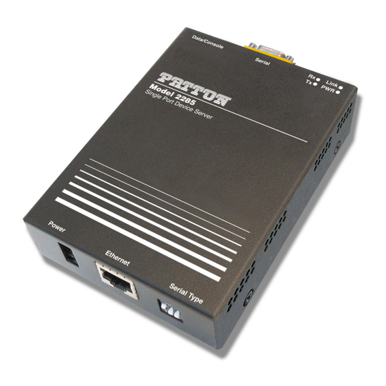
Model 2285
EtherBITS™ Universal Single-Port
Device Server
Getting Started Guide
Important
This is a Class A device and is intended for use in a light industrial environment. It is not intended nor approved for use in an industrial
or residential environment.
Sales Office:
+1 (301) 975-1000
Technical Support:
+1 (301) 975-1007
E-mail:
support@patton.com
WWW:
www.patton.com
Document Number: 08313U2-001 Rev. B
Part Number: 07M2285-UM
Revised: October 8, 2007
Advertisement
Table of Contents

Related Manuals for Patton electronics EtherBITS 2285


Summary of Contents for Patton electronics EtherBITS 2285
-
Page 1: Getting Started Guide
Model 2285 EtherBITS™ Universal Single-Port Device Server Getting Started Guide Important This is a Class A device and is intended for use in a light industrial environment. It is not intended nor approved for use in an industrial or residential environment. - Page 2 Patton Electronics Company, Inc. 7622 Rickenbacker Drive Gaithersburg, MD 20879 USA Tel: +1 (301) 975-1000 Fax: +1 (301) 869-9293 Support: +1 (301) 975-1007 Web: www.patton.com E-mail: support@patton.com Trademark Statement EtherBITS is a trademark of Patton Electronics Co.. Copyright © 2007, Patton Electronics Company. All rights reserved. The information in this document is subject to change without notice.
-
Page 3: Summary Table Of Contents
Contacting Patton for assistance ........................90 Compliance information ..........................93 Specifications ..............................95 Cable Recommendations ..........................99 Configuration files ............................. 104 Well-known port numbers ......................... 107 Guide to the Bios menu program ....................... 109 Using Model 2285 with Serial/IP ....................... 116... -
Page 4: Table Of Contents
Host ................................17 Session ................................17 Client/Server ..............................17 Acronyms ................................18 2 Getting started............................... 19 Introduction ................................20 Unpacking the Model 2285...........................20 Controls and indicators ............................20 Connecting the hardware............................22 Connecting to the network ..........................23 Connecting to the device ..........................23 Connecting power ............................23 Accessing the System Console..........................24 Using the System console ..........................24... - Page 5 Model 2285 Getting Started Guide Contents Primary and Secondary DNS ........................31 Using DHCP ..............................31 SNMP configurations............................33 MIB-II System objects Configuration ......................33 Access Control Configuration .........................34 Trap Receiver Configuration ...........................34 Management using SNMP ..........................35 Dynamic DNS Configuration ..........................35 SMTP Configuration ............................37 IP Filtering ................................38...
- Page 6 Model 2285 Getting Started Guide Contents Device Name Configuration..........................74 Date and Time Settings ............................74 Factory Reset .................................75 Firmware Upgrade..............................76 User administration ...............................79 6 System statistics............................. 80 Introduction ................................81 Network Interfaces Statistics..........................81 Serial Ports Statistics ..............................81 IP Statistics ..............................82 ICMP Statistics ..............................84 TCP Statistics................................85...
- Page 7 F Guide to the Bios menu program ....................... 109 Overview ................................110 Main menu................................110 RTC configuration menu ............................110 Hardware test menu ............................111 A 4.5. Firmware upgrade menu ...........................114 G Using Model 2285 with Serial/IP ....................... 116 Model 2285 vs. Serial/IP options.........................117 Connection example—Telnet and SSLv3 encryption ..................118...
-
Page 8: List Of Figures
Login screen of the Model 2285 web management ....... . . - Page 9 Connect to serial port of Model 2285 via Serial/IP ....... .
-
Page 10: List Of Tables
Model 2285 vs. Serial/IP option compatibility matrix table ....... . . -
Page 11: About This Guide
About this guide This guide describes installing and configuring a Patton Electronics Model 2285 EtherBITS™ Universal Sin- gle-Port Device Server. By the time you are finished with this guide, your device server will be fully connected and able to transfer data. -
Page 12: Precautions
Model 2285 Getting Started Guide About this guide Precautions Notes, cautions, and warnings, which have the following meanings, are used throughout this guide to help you become aware of potential problems. Warnings are intended to prevent safety hazards that could result in per- sonal injury. -
Page 13: General Observations
Avoid exposing the unit to direct sunlight and other heat sources Protect the unit from moisture, vapors, and corrosive liquids Factory default parameters Model 2285 EtherBITS Universal Single-Port Device Server have the following factory default parameters. Ethernet IP address: 192.168.161.5 Login: superuser... -
Page 14: Typographical Conventions Used In This Document
Model 2285 Getting Started Guide About this guide Typographical conventions used in this document This section describes the typographical conventions and terms used in this guide. General conventions The procedures described in this manual use the following text conventions: Table 1. General conventions... -
Page 15: Overview
Chapter 1 Overview Chapter contents Introduction ................................16 Glossary.................................17 MAC address ..............................17 Host ................................17 Session ................................17 Client/Server ..............................17 Acronyms ................................18... -
Page 16: Introduction
Internet by using DSL or cable modem connection. The built-in Dynamic DNS protocol of the Model 2285 enables you to access the serial devices with their own domain names. The Model 2285 also provides you with the system management functionality of system status display, firm- ware upgrade, remote reset and system log display by using various ways such as telnet, SSH, serial console port or web. -
Page 17: Glossary
Glossary This section defines commonly used terms in this manual. These terms are related to Internetworking, and defined in regards to their use with Model 2285. MAC address On a local area network or other network, the MAC (Media Access Control) address is the computer’s unique hardware number. -
Page 18: Acronyms
Model 2285 Getting Started Guide 1 • Overview Acronyms Acronym Definition Internet Service Provider Personal Computer Network Interface Card Media Access Control Local Area Network Unshielded Twisted Pair ADSL Asymmetric Digital Subscriber Line Address Resolution Protocol Internet Protocol ICMP Internet Control Message Protocol... -
Page 19: Getting Started
Chapter 2 Getting started Chapter contents Introduction ................................20 Unpacking the Model 2285...........................20 Controls and indicators ............................20 Connecting the hardware............................22 Connecting to the network ..........................23 Connecting to the device ..........................23 Connecting power ............................23 Accessing the System Console..........................24 Using the System console ..........................24... -
Page 20: Introduction
Model 2285 Getting Started Guide Controls and indicators The Model 2285 has four LED indicator lamps for status display. Upper-left lamp indicates the system power- on status. Lower-left lamp indicates the 10/100Base Ethernet Link status. Right two lamps indicate Receive and Transmit of the serial port. -
Page 21: Factory Reset Button Location
Model 2285 Getting Started Guide 2 • Getting started The Factory Reset button on the underside of the Model 2285 (see figure 1) is used to restore the device server to the factory default configuration. Factory Reset button Figure 1. Factory Reset button location The Serial Type DIP switches are used to configure the serial communication port (see... -
Page 22: Connecting The Hardware
Blinks whenever there is any outgoing data stream through the serial port of the Model 2285 Connecting the hardware This section describes how to connect the Model 2285 to your equipment for initial testing. • Connect the Model 2285 to an Ethernet hub or switch •... -
Page 23: Connecting To The Network
21). The other end of the Ethernet cable should be connected to a network port. If the cable is properly connected, the Model 2285 will have a valid connection to the Ethernet network. This will be indicated by: •... -
Page 24: Accessing The System Console
Accessing the System Console There are several ways to access the Model 2285. These methods are dependent on whether the user is located at a local site or a remote site, or whether the user requires a menu-driven interface, graphic menu system or CLI (Command Line Interface). -
Page 25: Using Remote Console
All the parameters can be stored into the non-volatile mem- ory space of the Model 2285, but the settings will not be stored until users enter “save” command on the menu. All the configuration change will be effective after entering “apply” command on the menu. -
Page 26: Accessing The Web Browser Management Interface
Figure 4. Telnet program set up example (TeraTerm Pro) 2. The user must log into the Model 2285. Type the user name and password. A factory default settings of the user name and password for CLI login are both root. -
Page 27: Login Screen Of The Model 2285 Web Management
– Password: superuser Note Before accessing the Model 2285 Web management page, the user must check the IP address (or resolvable Hostname) of the Model 2285 and sub- net mask settings. Figure 5. Login screen of the Model 2285 web management... -
Page 28: The Model 2285 Web Management Screen
[Apply Changes]. This option is available on the bottom of the menu bar. Only when the user selects [Apply changes] will the new parameter values be applied to the Model 2285 configura- tion. The user also can select [Save & apply] to save parameters and apply changes in one step. - Page 29 Chapter 3 Network configuration Chapter contents IP configuration ..............................30 Using a Static IP Address ..........................30 IP address ..............................31 Subnet mask ..............................31 Default gateway ............................31 Primary and Secondary DNS ........................31 Using DHCP ..............................31 SNMP configurations............................33 MIB-II System objects Configuration ......................33 Access Control Configuration .........................34 Trap Receiver Configuration ...........................34...
-
Page 30: Ip Configuration
When using a Static IP address, the user must manually specify all the configuration parameters associated with the IP address of the Model 2285. These include the IP address, the network subnet mask, the gateway com- puter and the domain name server computers. This section will look at each of these in more detail. -
Page 31: Ip Address
A subnet represents all the network hosts in one logical location, such as a building or local area network (LAN). The Model 2285 will use the subnet mask setting to verify the origin of all packets. If the desired TCP/IP host specified in the packet is in the same geographic location (on the local network segment) as defined by the subnet mask, the Model 2285 will establish a direct connection. - Page 32 Model 2285 address. In order to reserve the IP address in the DHCP network, the adminis- trator needs the MAC address of the Model 2285 found on the label sticker at the bottom of the Model 2285.
-
Page 33: Snmp Configurations
MIB-II System objects Configuration MIB-II System objects configuration sets the System Contact, Name, Location, and Authentication-failure traps used by the SNMP agent of the Model 2285. These settings provide the values used for the MIB-II sys- Name, sysContact, sysLocation, sysService and enableAuthenTrap. -
Page 34: Access Control Configuration
Model 2285 SNMP agent to exchange information and control actions. If there is no speci- fied IP address (all IP address are defaulted to 0.0.0.0), a manager from any host can access the Model 2285 SNMP agent. -
Page 35: Management Using Snmp
Dynamic DNS Configuration When users connect the Model 2285 to a DSL line or use a DHCP configuration, the IP address might be changed whenever it reconnects to the network. It can therefore be very difficult to post all related contacts for each new IP address. -
Page 36: Dynamic Dns Configuration
Model 2285 Getting Started Guide 3 • Network configuration By default, the Model 2285 only supports Dynamic DNS service offered at Dynamic DNS Network Services, LLC (www.dyndns.org). Contact Patton technical support for issues regarding other Dynamic DNS service providers. To use the Dynamic DNS service provided by Dynamic DNS Network Services, the user must set up an account in their Members’... -
Page 37: Smtp Configuration
3 • Network configuration Figure 11. SMTP Configurations SMTP Configuration The Model 2285 can be configured (see figure 11) to send an email notification when the number of system log messages reaches to certain value and/or when an alarm message is created due to an issue with serial port data. -
Page 38: Ip Filtering
Any host cannot access a specific service of the Model 2285 • Only one host of a specific IP address can access a specific service of the Model 2285 • Hosts on a specific subnet can access a specific service of the Model 2285 •... -
Page 39: Option And Ip Address/Mask
Input field to describe a specific range of host on the network. The user may allow a host or a group of hosts to access the Model 2285. The user must then enter the IP address and subnet of access. Any user on a remote host must stay in the specified subnet boundary to access the Model 2285. -
Page 40: Syslog Server Configuration
Overview If users want the Model 2285 to work as a server (TCP or UDP), the host acting as a client has to know the IP address of the Model 2285. However, under the dynamic IP address environment such as DHCP, arbitrary IP address can be assigned to the Model 2285, which means special consideration is required to access the current IP address of it. -
Page 41: Locating Server Configuration
Initially locating server feature is configured as “Disabled”. Figure 16. Locating server configuration Locating server communication protocol When the Model 2285 sends its IP address information to the locating server, data format will be as follows: Description Magic Cookie Data(0) Data(1) …... -
Page 42: Nfs Server Configuration
If the NFS service is enabled and the NFS server configuration is properly set up, the user may configure the storage location for the system log or port data log of the If there is a firewall between the Model 2285 and the SYSLOG server, there must be a rule that allows all outgoing and incoming UDP packets to travel across the Model 2285 as the NFS server. - Page 43 TCP keep-alive intervals: This represents the waiting period until a “keep-alive” packet is retransmitted. The default value is 5 seconds. By default, the Model 2285 will send the keep-alive packets 3 times with 5 seconds interval after 15 seconds have elapsed since the time when there’s no data transmitted back and forth.
-
Page 44: Serial Port Configuration
Chapter 4 Serial port configuration Chapter contents Overview ................................45 Serial Port Configuration............................47 Port Enable/Disable ............................48 Port Title ................................48 Host Mode Configuration ..........................48 TCP mode ..............................49 UDP mode ..............................53 Modem emulation mode ...........................54 Remote host configuration ..........................58 Cryptography configuration ..........................60 Secure Sockets Layer(SSL) cryptography method ..................60 RC4 cryptography method ........................63... -
Page 45: Overview
SNMP trap notification. This will enable the user to monitor the data from the attached device. Using MEMORY to store data will result in loss of all information when the Model 2285 is turned off. Use the NFS server to preserve the serial port log data. - Page 46 Model 2285 Getting Started Guide 4 • Serial port configuration Table 5. Serial port configuration parameters (Continued) SSLv3 Cryptography Baud rate Data bits Parity Stop bits Flow control Inter-character timeout (ms) Modem DTR behavior DSR behavior Enable/Disable modem Modem init-string...
-
Page 47: Serial Port Configuration
User can configure port parameters by clicking number or title of corresponding serial port (see figure 20). Figure 20. Selecting port parameters Serial Port Configuration Individual Port Configurations of the Model 2285 are classified into eight groups: • Port enable/disable • Port title •... -
Page 48: Port Enable/Disable
The Model 2285 operating mode is called the “host mode.” Three host modes are available: • TCP mode: The Model 2285 works as both TCP server and client. This mode works for most applications, since it will transfer the data either from serial port or from TCP port. If there is no connection established on a TCP port, the TCP port accepts a connection request from any registered remote hosts and relays the transmitted data to the coupled serial port. -
Page 49: Tcp Mode
[Closed]—It means “no connection state”. If the data transfer between a remote host and the Model 2285 is completed, the state is changed to this state as a result that either of the remote host or the Model 2285 sent a disconnection request. After this, the state is automatically changed to [Listen] mode. - Page 50 Incoming connection request(s) to the ports other than TCP Listening Port will be rejected. The Model 2285 does restrict the port number from 1024 to 65535 and if it is set as 0 only outgoing con- nection is permitted. (TCP server mode)
- Page 51 Max. allowed connection The Model 2285 supports up to 8 multiple connections from external host(s) to the serial port. If there are remote host connections by the remote host list configuration already, possible number of connection will be reduced (Max. allowed connection - remote host(s) connected already). For example, if user set Max.
-
Page 52: State Transition Diagram Of Tcp Mode
Figure 24. State Transition Diagram of TCP mode Inactivity Timeout When Inactivity Timeout function is enabled, connection between remote host(s) and Model 2285 will be closed automatically if there is no data transmission during the value which is set in Inactivity Timeout configuration. -
Page 53: Udp Mode
1) Operations If a remote host sends a UDP datagram to the one of UDP Local port of the Model 2285, Model 2285 first checks whether it is from one of the hosts configured on remote host configuration. If the remote host is one of the hosts configured on remote host configuration, then Model 2285 transfers the data through the serial port. -
Page 54: Modem Emulation Mode
Send to recent unlisted remote host If Send unlisted (Send to recent unlisted remote host) function is set as Yes, Model 2285 sends data to the remote host, which has connected Model 2285 recently. Recent unlisted remote host is a remote host, which has accessed a corresponding serial port of Model 2285 but is not configured on remote host configu-... -
Page 55: At Commands Supported In The Model 2285
Model 2285 Getting Started Guide 4 • Serial port configuration By using the modem emulation mode of the Model 2285, users can have their serial device connected to the Ethernet network easily, which is cheaper than using phone line modem. -
Page 56: At Commands Response Code
Model 2285 Getting Started Guide 4 • Serial port configuration Table 6. AT commands supported in the Model 2285 (Continued) Response Command Internal Operation (Verbose Code) ATHn [CR][LF] H, H0: Disconnect current TCP connection OK [CR][LF] All the data will be cleared... -
Page 57: Default Value Of S-Registers
Model 2285 Getting Started Guide 4 • Serial port configuration Table 7. AT commands Response Code Verbose Code Non-Verbose Code(Numeric Code) Description (After “ATV1” command executed) (After “ATV0” command executed) NO CARRIER Modem lost carrier signal ERROR Invalid command Table 8. Default value of S-Registers... -
Page 58: Remote Host Configuration
In TCP mode, user can also configure secondary remote host (Backup host) that will receive data from serial port if Model 2285 fails to connect to primary remote host. If a connection to the primary remote host can be Serial Port Configuration... - Page 59 And the maximum possible number of primary remote host is limited up to 4 remote connections. In UDP mode, user can only configure a primary remote host because there is no way for Model 2285 to check status of primary remote host, so secondary remote host is meaningless.
-
Page 60: Cryptography Configuration
Model 2285 Getting Started Guide 4 • Serial port configuration Cryptography configuration The Model 2285 supports encrypted sessions for only the TCP mode including modem emulation mode (not UDP mode). Figure 29. Cryptography configuration Secure Sockets Layer(SSL) cryptography method By setting the cryptography method as SSL, the Model 2285 can communicate with another device supporting SSLv3 cryptography method during encrypted sessions. - Page 61 Model 2285 Getting Started Guide 4 • Serial port configuration 2. The server sends the client the server’s SSL version number, cipher settings, randomly generated data, and other information the client needs to communicate with the server over SSL. The server also sends its own certificate and, if the client is requesting a server resource that requires client authentication, requests the...
-
Page 62: Typical Ssl Handshake Process
Figure 30. Typical SSL Handshake Process The Model 2285 can act as a SSL server or as a SSL client depending on status of TCP mode. If TCP connec- tion with SSL is initiated from remote host first, Model 2285 acts as a SSL server during the SSL handshake process. -
Page 63: Rc4 Cryptography Method
Serial port parameters To connect the serial device to the Model 2285 serial port, the serial port parameters of the Model 2285 should match exactly to that of the serial device attached. The serial port parameters are required to match this serial communication. - Page 64 Figure 33. Invalid UART type settings displayed on the Serial port configuration main screen • Baud rate: The valid baud rate for the Model 2285 is as follows: 75, 150, 200, 300, 600, 1200, 2400, 4800, 9600, 14400, 19200, 38400, 57600, 115200, and 230400. The factory default setting is 9600.
- Page 65 DSR input behavior as Allow TCP/UDP connection only by HIGH, TCP connection to remote host from Model 2285 is made only when the DSR status is changed from low to high. And TCP connec- tion to remote host is disconnected when the DSR status is changed from high to low. And also Model 2285 accepts TCP connection from the remote host only when the DSR status is high.
- Page 66 Inter-character timeout: This parameter defines the interval the Model 2285 fetches the overall serial data from its internal buffer. If there is an incoming data through the serial port, the Model 2285 stores data into the internal buffer. The Model 2285 transfers data stored in the buffer via TCP/IP, only if the internal buffer is full or if the inter-character time interval reaches the time specified in the inter-character timeout...
-
Page 67: Modem Configuration
Automatic release modem connection: If Automatic release modem connection is set as Enable, modem con- nection will be closed by Model 2285 if all TCP connections are closed. If this option is set as Disable, modem connection will not be closed by Model 2285 even if all TCP connections are closed. Please note that actual phone line connection will be closed if one of modems closes connection. -
Page 68: Port Logging
NFS server. If the internal memory is used to store port log data, the port log data will be cleared when the Model 2285 is turned off. To preserve the serial port log data, set the storage loca- tion to be the NFS server. -
Page 69: Port Event Handling Configurations
Port event handling: If the user wants to enable port event handling feature, set Port event handling as enable. This is a global parameter so if this feature is disabled, the Model 2285 does not take any actions on port events. -
Page 70: Event Keywords
SNMP trap notification: This parameter enables or disables SNMP trap notification feature of Model 2285. • Subject of SNMP trap: This parameter set the subject of SNMP trap that will be sent by Model 2285 when pre-defined keyword is detected. •... -
Page 71: System Administration
Chapter 5 System administration Chapter contents Introduction ................................72 System Logging ..............................72 Change Password..............................73 Device Name Configuration..........................74 Date and Time Settings ............................74 Factory Reset .................................75 Firmware Upgrade..............................76 User administration ...............................79... -
Page 72: Introduction
5 • System administration Introduction The Model 2285 displays the system status and the log data via a Status Display Screen. This screen is used for management purposes. System status data includes the model name, serial number, firmware version and the network configuration of the Model 2285. -
Page 73: Change Password
Figure 39. System log configuration and view The Model 2285 can also be configured to send log data automatically if the number of logs unsent reaches a pre-defined number. If enabled, the user must set parameters to initiate the creation of a email. These parame- ters would include the number of logs required to trigger an email, the recipient’s email address, etc. -
Page 74: Device Name Configuration
The Model 2285 has its own name for administrative purposes. Figure 41 shows the device name configura- tion screen. When user changes Device name, hostname of Model 2285 will be also changed. Figure 41. Device name configuration Note The user cannot set space character as a device name. If user sets blank as Device name then hostname is set as IP address of Model 2285 automatically. -
Page 75: Factory Reset
43. If the NTP feature is enabled, the Model 2285 will obtain the date and time information from the NTP server at each reboot. If the NTP server is set to 0.0.0.0, the Model 2285 will use the default NTP servers. In this case, the Model 2285 should be connected from the network to the Internet. The user may also need to set the time offset from UTC depending on the users’... -
Page 76: Firmware Upgrade
Model 2285 Getting Started Guide 5 • System administration Firmware Upgrade Firmware upgrades are available via serial, remote console or web interface. The latest upgrades are available on the Patton web site at http://www.patton.com/support/downloads/. Figure 45 shows the firmware upgrade web interface. - Page 77 Model 2285 Getting Started Guide 5 • System administration 3. Select from the firmware upgrade menu as below: login: root Password: # editconf [________________________________________________________________________ 1. Network configuration 2. Serial port configuration 3. System administration ________________________________________________________________________________ COMMAND (Display HELP: help)>3 System administration [____________________________________________________ 1.
- Page 78 5. Once the upgrade has been completed, the system will reboot to apply the changes 6. If the firmware upgrade fails, the Model 2285 will display error messages as shown below. It will also main- tain the current firmware version.
-
Page 79: User Administration
Model 2285 Getting Started Guide 5 • System administration User administration User can enable port authentication, then user should enter correct user ID and password of each port when he tries to access the serial port. The user ID and password for each serial port can be set using this menu. When user adds a new user for serial port, he can also assign permissible serial ports to the user selectively, as shown on figure... -
Page 80: System Statistics
Chapter 6 System statistics Chapter contents Introduction ................................81 Network Interfaces Statistics..........................81 Serial Ports Statistics ..............................81 IP Statistics ..............................82 ICMP Statistics ..............................84 Statistics................................85 UDP Statistics ..............................86... -
Page 81: Introduction
TCP/IP protocol suite. Network Interfaces Statistics Network interfaces statistics displays basic network interfaces usage of the Model 2285, lo and eth0. lo is a local loop back interface and eth0 is a default network interface of Model 2285. -
Page 82: Ip Statistics
Model 2285 Getting Started Guide 6 • System statistics IP Statistics The IP Statistics screen provides statistical information about packets/connections using an IP protocol. Defi- nitions and descriptions of each parameter are described below: Figure 51. IP statistics • Forwarding: Specifies whether IP forwarding is enabled or disabled. - Page 83 Model 2285 Getting Started Guide 6 • System statistics • InDelivers: Specifies the number of received datagrams delivered. • OutRequests: Specifies the number of outgoing datagrams that an IP is requested to transmit. This number does not include forwarded datagrams.
-
Page 84: Icmp Statistics
Model 2285 Getting Started Guide 6 • System statistics ICMP Statistics The ICMP Statistics screen provides statistical information about packets/connections using an ICMP proto- col. Definitions and descriptions of each parameter are described below: Figure 52. ICMP Statistics • InMsgs, OutMsgs: Specifies the number of messages received or sent. -
Page 85: Tcp Statistics
Model 2285 Getting Started Guide 6 • System statistics • NEchoReps, OutEchoReps: Specifies the number of echo replies received or sent. A computer sends an echo reply in response to receiving an echo request message. • InTimestamps, OutTimestamps: Specifies the number of time-stamp requests received or sent. A time- stamp request causes the receiving computer to send a time-stamp reply back to the originating computer. -
Page 86: Udp Statistics
Model 2285 Getting Started Guide 6 • System statistics • ActiveOpens: Specifies the number of active opens. In an active open, the client is initiating a connection with the server. • PassiveOpens: Specifies the number of passive opens. In a passive open, the server is listening for a connec- tion request from a client. -
Page 87: Cli Guide
Chapter 7 CLI guide Chapter contents Introduction ................................88 Flash partition ...............................88 Supported Linux Utilities ............................88 Shell & shell utilities ............................88 File and disk utils ............................88 System utilities ..............................88 Network utilities .............................88 Accessing CLI................................88... -
Page 88: Introduction
Introduction The root user can access the Linux console command line interface (CLI) of the Model 2285 via the serial con- sole or TELENT/SSH. In the CLI, the user can perform standard Linux commands to view the status of the Model 2285, edit the configuration, apply configuration changes. - Page 89 Model 2285 Getting Started Guide 7 • CLI guide 5. Login with the Model 2285 root account Telnet console: 1)telnet Pro_Series_ip_address SSH console: 1)ssh -2 Pro_Series_ip_address Note The Model 2285 only supports SSH v2 protocol. Accessing CLI...
-
Page 90: Contacting Patton For Assistance
Chapter 8 Contacting Patton for assistance Chapter contents Introduction ................................91 Contact information..............................91 Patton support headquarters in the USA ......................91 Alternate Patton support for Europe, Middle East, and Africa (EMEA) ............91 Warranty Service and Returned Merchandise Authorizations (RMAs)..............91 Warranty coverage ............................91 Out-of-warranty service ..........................92 Returns for credit... -
Page 91: Introduction
Model 2285 Getting Started Guide 8 • Contacting Patton for assistance Introduction This chapter contains the following information: • “Contact information”—describes how to contact PATTON technical support for assistance. • “Warranty Service and Returned Merchandise Authorizations (RMAs)”—contains information about the RAS warranty and obtaining a return merchandise authorization (RMA). -
Page 92: Out-Of-Warranty Service
Model 2285 Getting Started Guide 8 • Contacting Patton for assistance Out-of-warranty service Patton services what we sell, no matter how you acquired it, including malfunctioning products that are no longer under warranty. Our products have a flat fee for repairs. Units damaged by lightning or other catastro- phes may require replacement. - Page 93 Appendix A Compliance information Chapter contents EMC Compliance ..............................94 Radio and TV Interference (FCC Part 15) ......................94 CE Declaration of Conformity ..........................94 Authorized European Representative ........................94...
-
Page 94: A Compliance Information
Model 2285 Getting Started Guide A • Compliance information EMC Compliance • FCC Part 15, Class A • EN55022, Class A • EN55024 Radio and TV Interference (FCC Part 15) This equipment generates and uses radio frequency energy, and if not installed and used properly-that is, in strict accordance with the manufacturer's instructions-may cause interference to radio and television reception. - Page 95 Appendix B Specifications Chapter contents Serial interface ...............................96 Network interface..............................96 Protocols ................................96 Security .................................96 Modem emulation..............................96 Management .................................96 Security .................................97 Diagnostic LEDs ..............................97 Environmental...............................97 Physical .................................97 Power ..................................97...
-
Page 96: B Specifications
HTTPS • Secure terminal interface: SSH • Data Encryption: SSLv3 • IP address filtering Modem emulation Full support for AT commands Management • Web, Telnet, SSH, Serial console port or Model 2285 Manager • O/S support: Windows 98/ME/NT/2000/XP Serial interface... -
Page 97: Security
Model 2285 Getting Started Guide B • Specifications • System log: Automatic email delivery of error log • System statistics: Full-featured system status display • Firmware: Stored in Flash memory and upgradeable via telnet or web Security • Packet filtering firewall for controlled access to and from LAN/WAN. Support for 255 rules in 32 filter sets. - Page 98 Model 2285 Getting Started Guide B • Specifications Power...
- Page 99 Appendix C Cable Recommendations Chapter contents Ethernet Pin-outs ..............................100 Console and Serial port pin-outs..........................101 Ethernet wiring diagram ............................102 Serial wiring diagram ............................102 RS-232 serial wiring diagram ........................102 RS-422/485 serial wiring diagram .........................103...
-
Page 100: C Cable Recommendations
Model 2285 Getting Started Guide C • Cable Recommendations Ethernet Pin-outs The Model 2285 uses a standard Ethernet connector, which is a shielded connector that is compliant with the AT&T258 specifications. Table 9 shows the pin assignment and wire color. -
Page 101: Console And Serial Port Pin-Outs
Model 2285 Getting Started Guide C • Cable Recommendations Console and Serial port pin-outs The pin assignment of the Model 2285 DB9 connector is summarized in table 10. Each pin has a function according to the serial communication type configuration. -
Page 102: Ethernet Wiring Diagram
Model 2285 Getting Started Guide C • Cable Recommendations Ethernet wiring diagram Model 2285 Remote host Rx+(3) Rx+(3) Rx-(6) Rx-(6) Tx+(1) Tx+(1) Tx-(2) Tx-(2) Figure 58. Ethernet direct connection using crossover Ethernet cable Model 2285 Rx+(3) Rx+(3) Rx-(6) Rx-(6) Tx+(1) -
Page 103: Rs-422/485 Serial Wiring Diagram
Model 2285 Getting Started Guide C • Cable Recommendations RS-422/485 serial wiring diagram RS-485 (Half) **Data- **Data- Device Model 2285 120 ohm 120 ohm N = max 31 *Data+ *Data+ Data- Data+ Data- Data+ Device Device N - 1 Figure 61. RS-485 wiring diagram... -
Page 104: D Configuration Files
Appendix D Configuration files Chapter contents port1.conf................................105 filter.conf................................105 snmp.conf................................106... -
Page 105: Port1.Conf
Model 2285 Getting Started Guide D • Configuration files port1.conf /serial/*1/parameter/baudrate=9600 /serial/*1/parameter/databit=0 /serial/*1/parameter/stopbit=0 /serial/*1/parameter/parity=0 /serial/*1/parameter/flowcontrol=0 /serial/*1/parameter/interchar_to=0 /serial/*1/parameter/dtr_option=0 /serial/*1/parameter/dsr_option=0 /serial/*1/modem/modem_init_string=q1e0s0=2 /serial/*1/modem/modem_dcd_option=0 /serial/*1/modem/modem_auto_disconnection_enable=0 /serial/*1/modem/modem_enable=0 /serial/*1/event/event_email_enable=0 /serial/*1/event/event_snmp_enable=0 /serial/*1/event/event_notification_interval=30 /serial/*1/event/event_enable=0 /serial/*1/hostmode/accept_unlisted=1 /serial/*1/hostmode/send_unlisted=1 /serial/*1/enable=1 /serial/*1/title=Port #1 /serial/*1/hostmode/mode=0 /serial/*1/hostmode/port=7001 /serial/*1/hostmode/userauth=0 /serial/*1/hostmode/telnet=0 /serial/*1/hostmode/max_connection=8 /serial/*1/hostmode/cyclic_time=0 /serial/*1/hostmode/inactive_time=0 filter.conf /network/filter/specification/telnet=1... -
Page 106: Snmp.conf
Model 2285 Getting Started Guide D • Configuration files snmp.conf /network/snmp/syscontact=administrator /network/snmp/sysname=ProSeries /network/snmp/syslocation=my location /network/snmp/sysservice=7 /network/snmp/powerontrapenable=0 /network/snmp/authtrapenable=1 /network/snmp/linkuptrapenable=0 /network/snmp/logintrapenable=0 /network/snmp/nms/*1=0.0.0.0 public /network/snmp/nms/*2=0.0.0.0 public /network/snmp/nms/*3=0.0.0.0 public /network/snmp/nms/*4=0.0.0.0 public /network/snmp/trap/*1=0.0.0.0 public /network/snmp/trap/*2=0.0.0.0 public /network/snmp/trap/*3=0.0.0.0 public /network/snmp/trap/*4=0.0.0.0 public snmp.conf... -
Page 107: E Well-Known Port Numbers
Appendix E Well-known port numbers Chapter contents Introduction ................................108... -
Page 108: Introduction
Model 2285 Getting Started Guide E • Well-known port numbers Introduction Port numbers are divided into three ranges: Well Known Ports, Registered Ports, and Dynamic and/or Private Ports. Well Known Ports are those from 0 through 1023. Registered Ports are those from 1024 through 49151. -
Page 109: F Guide To The Bios Menu Program
Appendix F Guide to the Bios menu program Chapter contents Overview ................................110 Main menu................................110 RTC configuration menu ............................110 Hardware test menu ............................111 A 4.5. Firmware upgrade menu ...........................114... -
Page 110: Overview
Overview The bios menu provides a way to recover the Model 2285 unit, by using TFTP, as a disaster recovery option and to diagnose the system hardware. If the user presses the <ESC> key within 3 seconds after the Model 2285 unit is powered up, the user will enter the bios menu program. -
Page 111: Hardware Test Menu
To perform the test on the Ethernet and UART properly, the user must con- nect an Ethernet cable to the Ethernet port of the Model 2285 and must plug the loopback connector to all the serial ports of the Model 2285. There must exist a remote host with a valid IP address. - Page 112 Model 2285 Getting Started Guide F • Guide to the Bios menu program ----------------------------------------------------------------------------- Hardware Test ----------------------------------------------------------------------------- Select menu 0. Test Mode - Looping(Without External test in Auto Test) 1. Auto test 2. DRAM test 3. FLASH test 4. EEPROM test 5.
- Page 113 Model 2285 Getting Started Guide F • Guide to the Bios menu program [UART] <--Internal Loop Test--> Port # 1 test in progressing(MODE)------------------------[ RS232] (Read/WRite)------------------[ SUCCESS] Port # 2 test in progressing(MODE)------------------------[ RS232] (Read/WRite)------------------[ SUCCESS] Port # 3 test in progressing(MODE)------------------------[...
-
Page 114: A 4.5. Firmware Upgrade Menu
Model 2285 Getting Started Guide F • Guide to the Bios menu program For each hardware component test, the user can skip a test by pressing the <ESC> key. ------------------------------------------------------------------------------- Hardware Test ------------------------------------------------------------------------------- Select menu 0. Test Mode - One Time 1. - Page 115 Model 2285 Getting Started Guide F • Guide to the Bios menu program If the user selects [Start firmware upgrade], a confirmation message will be displayed on the screen. If the user enters 'y', the firmware upgrade process will start. This process cannot be stopped until it has finished.
-
Page 116: G Using Model 2285 With Serial/Ip
Appendix G Using Model 2285 with Serial/IP Chapter contents Overview ................................110 Main menu................................110 RTC configuration menu ............................110 Hardware test menu ............................111 A 4.5. Firmware upgrade menu ...........................114... -
Page 117: Model 2285 Vs. Serial/Ip Options
No login Telnet SSLv3 or TLSv1/ required SSLv3 only Note The Model 2285 support only the SSLv3 encryption method, so user should select one of “SSLv3 or TSLv1” option or “SSLv3 only” option in Serial/IP. Model 2285 vs. Serial/IP options... -
Page 118: Connection Example-Telnet And Sslv3 Encryption
Host mode = TCP Port numer = 7001 Telnet protocol = Enabled Figure 63. Host mode configuration 2. Set Cryptography configuration of serial port #1 of Model 2285 as follows: SSL enable = Enable Figure 64. Cryptography configuration Connection example—Telnet and SSLv3 encryption... -
Page 119: Select Ports On Serial/Ip Control Panel
#1 of Model 2285 by pressing “Select Ports” button. Figure 65. Select Ports on Serial/IP Control Panel 4. Step 4. Enter IP address of Server (IP address of Model 2285) and Port number (port number of serial port #1) correctly. -
Page 120: Set Parameters On Serial/Ip Control Panel
Figure 66. Set parameters on Serial/IP Control Panel 5. Open the terminal emulation program and select the corresponding COM port. The user can use the serial port of Model 2285 using his local terminal emulation program as if it is one of COM ports on his PC. -
Page 121: Serial/Ip Trace Window
Model 2285 Getting Started Guide G • Using Model 2285 with Serial/IP 6. User can monitor or trace the connection status using Serial/IP Port Monitor or Trace window. Figure 68. Serial/IP Trace Window Connection example—Telnet and SSLv3 encryption...
Need help?
Do you have a question about the EtherBITS 2285 and is the answer not in the manual?
Questions and answers