Table of Contents
Advertisement
IMPORTANT SAFETY INFORMATION: Always read this manual first before attempting to service this
fireplace. For your safety, always comply with all warnings and safety instructions contained in this
manual to prevent personal injury or property damage.
Dimplex North America Limited
1367 Industrial Road Cambridge ON Canada N1R 7G8
1-888-346-7539 www.dimplex.com
In keeping with our policy of continuous product development, we reserve the right to make changes without notice.
© 2011 Dimplex North America Limited
Service Manual
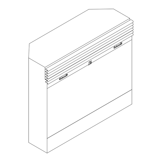
26" Fireplace
With 3-Stage Remote
Model Number:
DF2600
UL Part Number
6901170859
6901170959
6901181300
REV
PCN
DATE
00
-
21-SEP-11
7400430000R00
Advertisement
Table of Contents

Summary of Contents for Dimplex DF2600
- Page 1 Dimplex North America Limited 21-SEP-11 1367 Industrial Road Cambridge ON Canada N1R 7G8 1-888-346-7539 www.dimplex.com In keeping with our policy of continuous product development, we reserve the right to make changes without notice. © 2011 Dimplex North America Limited 7400430000R00...
-
Page 2: Table Of Contents
NOTE: Procedures and techniques that are considered important enough to emphasize. CAUTION: Procedures and techniques which, if not carefully followed, will result in damage to the equipment. WARNINg: Procedures and techniques which, if not carefully followed, will expose the user to the risk of fire, serious injury, or death. www.dimplex.com... -
Page 3: Operation
To locate controls see Figure 2. CAUTION: If you need to continuously reset the heater, disconnect power and call Dimplex customer service at A. ON/OFF SWITCH 1-888-DIMPLEX (1-888-346-7539). The ON/OFF SWITCH supplies power to all fireplace Remote Control functions (Heater/Flame). -
Page 4: Maintenance
Close the battery cover top. Battery must be recycled or disposed of properly. Examine the bulbs to determine which bulbs require Check with your Local Authority or Retailer for replacement. recycling advice in your area. Hold the socket while unscrewing the bulb www.dimplex.com... -
Page 5: Glass Cleaning
Figure 4 Figure 5 Hold the socket while screwing in the new bulb. Figure 6 UPPER LIgHT BULB REQUIREMENTS: Quantity of 2 clear chandelier or candelabra bulbs with an E-12 (small) socket base, 15 watt rating. Please refer to the label adjacent to the upper lamps for the correct wattage for your model. -
Page 6: Exploded Parts Diagram
....3000250100RP REMOTE CONTROL ....3000370600RP PARTIALLY REFLECTIVE GLASS ..6900100200RP www.dimplex.com... -
Page 7: Wiring Diagram
WIRINg DIAgRAM... -
Page 8: On/Off Switch Replacement
Remove the firebox from the mantel. grille section, grasping the sides of the trim and pulling Lower the grille covering the controls. forward, away from the firebox, releasing the retainer clips. Remove the 6 retaining screws on the edges along the www.dimplex.com... -
Page 9: Flicker Motor/Flicker Rod Replacement
top cover: 2 on the left; 2 on the right; 2 on the back. ember-bed, not the logs themselves. Remove the top, placing it upside down on the top of NOTE: Log-set fits tightly into firebox. Some force the unit being careful not to damage any of the wiring. may be necessary to remove. -
Page 10: 3-Position Switch Replacement
Remove the firebox from the mantel. Remove the 6 retaining screws on the edges along the top cover: 2 on the left; 2 on the right; 2 on the back. www.dimplex.com... -
Page 11: Power Cord Replacement
POWER CORD REPLACEMENT Remove the top, placing it upside down on the top of the unit being careful not to damage any of the wiring. Tools Required: Phillips head screwdriver Locate the Remote Control Receiver, next to the ther- Needle nosed pliers mostat control, and disconnect the wiring connections WARNINg: If the fireplace was operating prior to noting their original locations. -
Page 12: Assembly Component Pictures
ASSEMBLY COMPONENT PICTURES EXTERIOR VIEW OF MANUAL CONTROLS Flame Speed Control 3-Position Switch Knob Interior Light Control LED Indicator Lights On/Off Switch Thermostat Control Knob Front Grille Open INTERIOR VIEW FROM THE BOTTOM Light Sockets Flicker Rod Flicker Motor www.dimplex.com... - Page 13 INTERIOR VIEW OF RIgHT SIDE, TOP & FRONT PANEL Potentiometers (Flame Speed & Dimmer Con- Heater Assembly (blower trols) motor; fan; elements) ON/OFF Switch Flame Speed Control Board Dimmer Control Board Terminal Block INTERIOR VIEW OF LEFT SIDE, TOP & FRONT PANEL 3-Position Switch Thermostat Control Remote Control Receiver...
-
Page 14: Troubleshooting Guide
Burnt light bulbs Replace light bulbs Flame Shutter Defective Flicker motor Replace Flicker motor Defective Flame Speed Control Board Replace Flame Speed Control Board Light leaking around the log set Log set not positioned properly Check log set for proper fit www.dimplex.com... - Page 15 PROBLEM CAUSE SOLUTION Heater Heater is not turning off Improper operation Refer to Operation Section Defective Thermostat Replace Thermostat Heater is not turning on, but Improper operation Refer to Operation Section flame effect is still functioning Loose wiring Trace wiring in unit. Defective Thermostat Replace Thermostat Defective Heater Assembly...


Need help?
Do you have a question about the DF2600 and is the answer not in the manual?
Questions and answers