Table of Contents
Advertisement
Quick Links
Service Manual
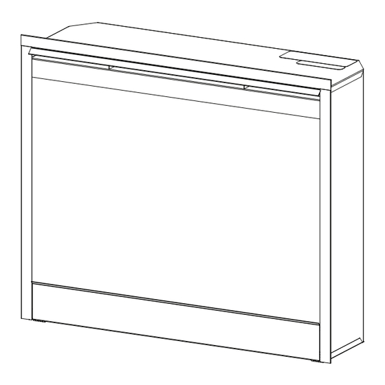
26" Self Trimming Export Fireplace with 3 Stage On/Off
Remote
Model Numbers:
DF2608-EU
DF2608-AU
Dimplex North America Limited
1367 Industrial Road
Cambridge ON Canada N1R 7G8
1-888-346-7539
www.dimplex.com
In keeping with our policy of continuous product development, we reserve the right to make changes without notice.
- MOD / to A
- MOD /
REV
PCN
DATE
00
11554
Aug 6, 09
7400230000rev00
Advertisement
Table of Contents

Related Manuals for Dimplex DF2608-AU


Summary of Contents for Dimplex DF2608-AU
- Page 1 DF2608-AU - MOD / DATE 11554 Aug 6, 09 Dimplex North America Limited 1367 Industrial Road Cambridge ON Canada N1R 7G8 1-888-346-7539 www.dimplex.com In keeping with our policy of continuous product development, we reserve the right to make changes without notice.
-
Page 2: Table Of Contents
Table Of Contents Page 3 Operation Page 5 Exploded Parts Diagram and Parts List - DF2608-EU/AU Page 6 Wiring Diagram and Schematic - DF2608-EU/AU Page 7 Front Glass Replacement Page 7 Light Bulb Replacement Page 8 Mirror Replacement Page 8 Main On/Off Switch Replacement Page 9 Flame/Heat Selection Switch Replacement... -
Page 3: Operation
Operation Resetting the Temperature Cutoff Switch This unit is equipped with a thermostat which controls the This section will explain the function of each convenient temperature of the room by turning the heater on and off. control (Figure 2). The heater is protected with a safety device to prevent To access the controls, flip open the control panel cover overheating. - Page 4 Battery Replacement Level : The flame effect remains on, the heater is activated to the low heat setting, and the first and second red To replace the battery: indicator lights flash momentarily. 1. Slide battery cover open on the hand held transmitter Level : The flame effect remains on, the heater is set to (Figure 3).
- Page 5 14. Remote Transmitter 3000550300RP 7. Flame Action Control 3000410100RP 15. Remote Receiver 3000550100RP 8. Light Dimmer Control 3000420100RP 16. Remote Daughter Board 3000550200RP 9. Cord Set (DF2608-EU) 4100080259RP 17. Terminal Block 4000070100RP Cord Set (DF2608-AU) 4100080159RP 18. Flicker Rod 5901250100RP...
- Page 6 Wiring Diagram - DF2608-EU/AU...
-
Page 7: Front Glass Replacement
Front Glass Replacement Upper Bulb Requirements: A quantity of two (2) chandelier or candelabra bulbs with an If unit was operating prior to servicing allow at least 10 E-14 (small) socket base, 25 Watt rating are required. minutes for light bulbs and heating element to cool off to avoid accidental burning of skin. -
Page 8: Mirror Replacement
! NOTE: Log set fits tightly into firebox, some force may be Figure 6 necessary to remove. 6. Disconnect LED harness. Mirror 7. Set log set in front of fireplace. 8. Remove flicker rod by sliding flicker rod to the left away from the flicker motor and lift out. -
Page 9: Flame/Heat Selection Switch Replacement
Figure 9 Figure 8 Main ON/OFF Mounting Studs (2) Switch Flame/Heat Selection On/Off Switch Retainer Clips (one top, one bottom) Wire Harness to 5. Depress the two (2) retainer clips on the top and bottom Remote Board of the switch and push the switch out of the cover. 6. -
Page 10: Flame Action Control Replacement
Figure 10 Figure 11 Retaining Retaining Potentiometer Flame Action Potentiometer Control Board Light Dimmer Control Board Mounting Studs (4) Mounting Studs (4) 6. Pull off the Flame Action Control knob and unscrew ! NOTE: If mounting studs are cut, replacement mounting the retaining nut (Figure 11). -
Page 11: Thermostat Control Replacement
(you may have to tip the bottom of the fireplace up 9. Remove the rubber bushing from the motor shaft by if it is laying on its back), four (4) screws in the front applying needle nose pliers to the motor shaft and twist directly under the control panel;... -
Page 12: Remote Control Board Replacement
Figure 15 Figure 14 Remote Control Receiver Screw Thermostat Mounting Studs (4) Remote Control Replacement Remote Control hand held transmitters require no replacement procedure however, a reinitialization procedure may need to be followed. Refer to Page 1 for the Remote Initialization procedure. -
Page 13: Heater Assembly Replacement
Figure 16 Figure 17 Screws to Remove Log Driver Control Board may be a snug fit inside the firebox. Orientate yourself with the placement of the Heater Assembly and wiring as shown in Figure 18. Mounting Studs (4) Figure 18 Heater Assembly Top Panel Heating Element... -
Page 14: Power Cord Replacement
Power Cord Replacement Figure 20 If the fireplace was operating prior to servicing allow at least 10 minutes for light bulbs and heating element to cool off to 3 Position avoid accidental burning of skin. Switch Disconnect power before attempting any maintenance or cleaning to reduce the risk of electric shock or damage to persons.
Need help?
Do you have a question about the DF2608-AU and is the answer not in the manual?
Questions and answers