Table of Contents
Advertisement
Quick Links
w
w
w
w
w
Duct Packaged Cooling System
Installation, Operation & Care Manual
WM-4500DS WM-6500DS WM-8500DS
w
w
w
w
R
e
a
d
a
n
d
s
a
R
e
a
d
a
n
d
s
a
.
w
i
n
e
m
a
t
e
.
c
o
m
w
.
w
i
n
e
m
a
t
e
.
c
o
m
w
.
v
i
n
o
t
e
m
p
.
c
o
m
w
.
v
i
n
o
t
e
m
p
.
c
o
m
v
e
t
h
e
s
e
i
n
s
t
r
v
e
t
h
e
s
e
i
n
s
t
r
u
c
t
i
o
n
s
u
c
t
i
o
n
s
Advertisement
Table of Contents

Related Manuals for Vinotemp WINE-MATE WM-4500DS


Summary of Contents for Vinotemp WINE-MATE WM-4500DS
- Page 1 Duct Packaged Cooling System Installation, Operation & Care Manual WM-4500DS WM-6500DS WM-8500DS...
-
Page 2: Important Safety Information
Important Safety Information WARNING: • Do not use a ground fault interrupter (GFI). • A dedicated 30 AMP circuit is required. - 1 -... -
Page 3: Table Of Contents
Table of Contents Cellar Construction.…………………………….……………..3 Features & Specifications…………………….….…………..4 Temperature & Humidity……….…………..………..……….6 Care Guide…………………………………………………….10 User’ Troubleshooting…….………………………………...11 Installer’s Instructions………….…..….……..…………….14 Service Instructions…………………………….……………18 Electrical Wirings..…………….…..….……..………………24 Customer Support……………………………………………28 Warranty……………………………………………………….29 - 2 -... -
Page 4: Cellar Construction
Cellar Construction This is only a guide and shall be considered as minimum requirements. All interior walls and floors shall have a vapor barrier and a minimum of R13 insulation. All exterior walls and ceiling shall have a vapor barrier and a minimum of R19 insulation. -
Page 5: Features & Specifications
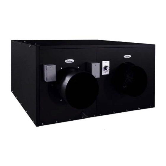
Features and Specifications • Wine-Mate duct packaged cooling systems WM-4500~8500DS are designed and used to provide a cold temperature between 50~65 °F for a properly insulated wine cellar. • The wine cellar will maintain humidity range within 50~70% RH. • These temperature and humidity ranges like in natural caves are optimized for long term storage of wine. - Page 6 NOTE: To prepare rough-in, leave minimum 4” clearances for electrical wiring and refrigeration piping. The specifications and dimensions are listed as follows: Dimension Btu/h Cellar Size Model No Refrigerant Electrical Rating Weight (lb) L”xW”xH” (cu ft) 4500 WM-4500DS 45x34x23 1000 R134a 115V-60HZ-8A 6500...
-
Page 7: Temperature & Humidity
Temperature and Humidity 1. Use of the controller Fig. 3 Temperature Controller 1) Keys SET: To display target set point; in programming mode it selects a parameter or confirm an operation. (DEF): To start a manual defrost. (UP): To see the maximum stored temperature; in programming mode it browses the parameter codes or increases the displayed value. - Page 8 4) Alarm Signals The alarm codes are described as follows. MESSAGE CAUSE FUNCTION Temperature probe faulty Compressor switching to Con and CoF Probe temperature ALU higher than the High temperature alarm setting temperature; Outputs unchanged Probe temperature ALL lower than the Low temperature alarm setting temperature;...
- Page 9 5. How to calibrate the air temperature probe If the actual cellar temperature differs from the displaying temperature, set ot = actual cellar temperature minus displaying temperature. 6. How to adjust defrost cycle In case there is excessive frost, the parameters FnC = C-y, idF = 6 and MdF = 20 can be used to avoid defrost.
- Page 10 3) Press up/down keys to scroll to the required parameter within 10 sec. 4) Press the “SET” key to display its value. 5) Use up/down keys to change its value within 10 sec. 6) Press “SET” to store the new value. 7) To exit: Press SET + or wait 15sec without pressing a key.
-
Page 11: Care Guide
Care Guide In general, always unplug system or disconnect power while doing care. 1. Coil Cleaning • Clean the condenser coil regularly. Coil may need to be cleaned at least every 6 months. • Use a vacuum cleaner with an extended attachment to clean the coil when it is dusty or dirty. -
Page 12: User' Troubleshooting
User’s Troubleshooting This Troubleshooting Chart is not prepared to replace the training required for a professional refrigeration service person, not is it comprehensive. Complaint Possible Causes Response a. Power cord not plugged a. Check power cord 1. Unit not b. No power from supply b. - Page 13 high or not b. Cellar too large b. Check for excessive size c. Ambient temperature too high c. Check installation location cooling and d. Exhaust restricted d. Leave minimum 3 feet clearance for running the hot air exhaust side and leave continually minimum 1 foot clearance for the ambient air intake side...
- Page 14 fan running b. Failed components b. Check start relay, start capacitor, overload protector, compressor. c. Low refrigerant c. Call service condensing unit not running a. Evaporator air flow restriction a. Check for fans and CFM 13.Evaporator b. Condenser air flow restriction b.
-
Page 15: Installer's Instructions
WINE-MATE packaged duct system is shipped ready for use only after a certified refrigeration technician has properly installed the system. Proper installation is critical. Vinotemp can only warrant the quality of the components. The installation of the system must be warranted by the installer. Installation of the system must be done in accordance with all state and local building and electrical codes. - Page 16 Fig. 5 Temperature Controller (4.25”L X 3.75D X 4.25”H) Parts included: Packaged Cooling system Temperature Controller (4.5”LX4.5”WX3.75”D) + Air Probe Parts not included: Insulated ducts CAUTION: Low ambient condition kit is required if the installation area will be below 50°F. 2.
- Page 17 3. Mounting • The unit must be mounted on a floor or slab that is level and strong enough to support up to 300lb. • There are six ½” bolts required to secure the unit base. • There is a gravity drain system used, so the unit shall be installed level or with a slight slope downward the drain connection and the drain line shall be installed slope down toward the drain.
- Page 18 • It is necessary to check the air flow to meet the specified CFM. It may use fan speed control to adjust the system refrigeration performance to achieve 8- 10°F differential between return air and supply air while wine room temperature is maintained 55°F.
-
Page 19: Service Instructions
Service Instructions 1. Service Valve Operations BACK POSITION FRONT POSITION MIDDLE POSITION Fig. 7 ROTALOCK Valve Operation BACK POSITION FRONT POSITION MIDDLE POSITION Fig. 8 Base Valve Operation 1 - Process & Manometer; 2 – Receiver Discharge or Compressor Suction 3 –... - Page 20 A. P70 Single/Dual Control B. PS2 Dual Control Fig. 9 Adjustable Pressure Control Low ambient condition kit (if applicable) Use of the condenser fan control Head pressure setting: Cut in=170 psig; Cut out=120 psig; Differential=50 psig It closes on rise of pressure. It may need to adjust the setting in the field to avoid fan short cycle.
- Page 21 Use of the crankcase heater The crankcase heater is installed around the lower part of the compressor and shall be turned on all the time. The heater is self-regulated. 3. Piping, Checking and Testing NOTES: • The line connection sizes of liquid filter & indicator, the valve connection sizes of condensing unit and the line connection sizes of evaporator unit are not necessary the same as the listed refrigeration line sizes.
- Page 22 • If the low ambient condition kit is used, turn off the compressor before power the condensing unit. Only turn on the compressor after the condensing unit has been powered for 12 hours. 1) Evacuate the system; both discharge and suction valves must be in the middle positions during evacuating.
- Page 23 Fig. 11 Fan Speed Control Fig. 12 Expansion Valve Fig. 13 Liquid Filter Fig. 14 Liquid Indicator 6. Pressure, Superheat and Subcooling Readings CAUTION: To read properly the service valves must be in the middle positions. Complaint Possible Causes 1) High suction pressure and low head pressure 1) Compressor may be bad Zero superheat and zero subcooling 2) High suction pressure and low head pressure...
- Page 24 10) Low suction pressure and low head pressure 10) Air restricted evaporator, Low superheat and low subcooling evaporator iced 11) Low suction pressure and low to normal head 11) Evaporator restricted pressure High superheat and normal to high subcooling 12) Low suction pressure and normal head pressure 12) Expansion valve restricted High superheat and normal subcooling 13) Low suction pressure and high head pressure...
-
Page 25: Electrical Wirings
Electrical Wiring Diagrams CAUTION: • Hidden lines are the field wirings • Use minimum 14 gauge wires for power lines. • If equipped with low ambient condition kit, use low ambient temperature wiring diagrams. • A safety switch is always recommended for the condensing unit. Fig. - Page 26 Fig. 16 WM-6500DS Electrical Wiring Diagram Fig. 17 WM-8500DS Electrical Wiring Diagram - 25 -...
- Page 27 Fig. 18 Low Ambient Temperature WM-4500DS-LA Electrical Wiring Diagram Fig. 19 Low Ambient Temperature WM-6500DS-LA Electrical Wiring Diagram - 26 -...
- Page 28 Fig. 20 Low Ambient Temperature WM-8500DS-LA Electrical Wiring Diagram - 27 -...
-
Page 29: Customer Support
Customer Support If you need further assistance, please contact us at: Vinotemp International 17631 South Susana Road Rancho Dominguez, CA 90221 Tel: (310) 886-3332 Fax: (310) 886-3310 Email: info@vinotemp.com - 28 -... -
Page 30: Warranty
BTU/H. While every effort has been made to provide accurate guidelines, VINOTEMP can not warranty its units to cool a particular enclosure. In case of failure, VINOTEMP cooling units must be repaired by the factory or its authorized agent. Repairs or modifications made by anyone else will void the warranty. - Page 31 VINOTEMP will, at its discretion, repair or replace the unit and return it free of charge to the original retail customer. If the unit is found to be in good working order, or beyond the initial twelve month period, it will be returned freight collect.
Need help?
Do you have a question about the WINE-MATE WM-4500DS and is the answer not in the manual?
Questions and answers