Table of Contents
Advertisement
Quick Links
Rack Split Cooling System
Installation, Operation & Care Manual
WM-2500SSVWC WM-4500SSVWC WM-6500SSVWC
R
e
a
d
a
n
R
e
a
d
a
n
w
w
w
.
w
i
n
e
m
a
t
e
.
c
o
w
w
w
.
w
i
n
e
m
a
t
e
.
c
o
w
w
w
.
v
i
n
o
t
e
m
p
.
c
o
w
w
w
.
v
i
n
o
t
e
m
p
.
c
o
d
s
a
v
e
t
h
e
s
e
i
n
d
s
a
v
e
t
h
e
s
e
i
n
m
m
m
m
s
t
r
u
c
t
i
o
n
s
s
t
r
u
c
t
i
o
n
s
Advertisement
Table of Contents

Subscribe to Our Youtube Channel
Related Manuals for Vinotemp Wine-Mate WM-2500SSVWC


Summary of Contents for Vinotemp Wine-Mate WM-2500SSVWC
- Page 1 Rack Split Cooling System Installation, Operation & Care Manual WM-2500SSVWC WM-4500SSVWC WM-6500SSVWC...
-
Page 2: Important Safety Information
Important Safety Information WARNING: • Do not use a ground fault interrupter (GFI). • A dedicated 20 AMP circuit for WM-2500SSVWC and 30 AMP for WM- 4500~6500SSVWC are required. - 1 -... -
Page 3: Table Of Contents
Table of Contents Cellar Construction.…………………………….……………..3 Features & Specifications…………………….….…………..4 Temperature & Humidity……….…………..………..……….6 Care Guide…………………………………………………….10 User’ Troubleshooting…….………………………………...11 Installer’s Instructions………….…..….……..…………….14 Electrical Wirings..…………….…..….……..………………24 Customer Support……………………………………………26 Warranty……………………………………………………….27 - 2 -... -
Page 4: Cellar Construction
Cellar Construction This is only a guide and shall be considered as minimum requirements. All interior walls and floors shall have a vapor barrier and a minimum of R13 insulation. All exterior walls and ceiling shall have a vapor barrier and a minimum of R19 insulation. -
Page 5: Features & Specifications
Features and Specifications • Wine-Mate rack split cooling systems WM-2500~6500SSVWC are designed and used to provide a cold temperature between 50~65 °F for a properly insulated wine cellar. • The wine cellar will maintain humidity range within 50~70% RH. • These temperature and humidity ranges like in natural caves are optimized for long term storage of wine. - Page 6 NOTE: To prepare rough-in, leave minimum 4” clearances for electrical wiring and refrigeration piping. The specifications and dimensions are listed as follows: Electrical Weight (lb) Cond Unit Btu/h Cellar Size Model No Evap Unit Refrigerant Evap Unit/ Evap Unit/ L”xD”xH” (cu ft) Cond Unit Cond Unit...
-
Page 7: Temperature & Humidity
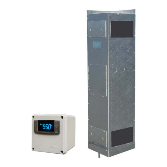
Temperature and Humidity 1. Use of the controller Fig. 2 Temperature Controller 1) Keys SET: To display target set point; in programming mode it selects a parameter or confirm an operation. (DEF): To start a manual defrost. (UP): To see the maximum stored temperature; in programming mode it browses the parameter codes or increases the displayed value. - Page 8 4) Alarm Signals The alarm codes are described as follows. MESSAGE CAUSE FUNCTION Temperature probe faulty Compressor switching to Con and CoF Probe temperature ALU higher than the High temperature alarm setting temperature; Outputs unchanged Probe temperature ALL lower than the Low temperature alarm setting temperature;...
- Page 9 5. How to calibrate the air temperature probe If the actual cellar temperature differs from the displaying temperature, set ot = actual cellar temperature minus displaying temperature. 6. How to adjust defrost cycle In case there is excessive frost, the parameters FnC = C-y, idF = 6 and MdF = 20 can be used to avoid defrost.
- Page 10 3) Press up/down keys to scroll to the required parameter within 10 sec. 4) Press the “SET” key to display its value. 5) Use up/down keys to change its value within 10 sec. 6) Press “SET” to store the new value. 7) To exit: Press SET + or wait 15sec without pressing a key.
-
Page 11: Care Guide
Care Guide In general, always unplug system or disconnect power while doing care. 1. Condenser Water Line Cleaning • To clear any sediment that may accumulate, the water regulating valve may be manually flushed. • Insert screwdrivers under both sides of the valve spring guide and lift upwards to flush. -
Page 12: User' Troubleshooting
User’s Troubleshooting This Troubleshooting Chart is not prepared to replace the training required for a professional refrigeration service person, not is it comprehensive. Complaint Possible Causes Response a. Power cord not plugged a. Check power cord 1. Unit not b. No power from supply b. - Page 13 high or not b. Cellar too large b. Check for excessive size c. Cellar ambient temperature too c. Check installation location cooling and high running d. Malfunctioning fans d. Check for evaporator fan continually e. Evaporator airflow e. Check for air restrictions, air short- circulation, grille directions Improper condenser cooling Check water flow...
- Page 14 inside ducts b. Continually running not stopping b. raise temperature setting increase defrost cycle c. Too cold supply air c. Increase flow raise temperature setting a. Duct not insulated a. Check for insulation 13.Condensate b. High humidity b. Use dehumidifier outside c.
-
Page 15: Installer's Instructions
WINE-MATE split system is shipped as components and is ready for use only after a certified refrigeration technician has properly installed the system. Proper installation is critical. Vinotemp can only warrant the quality of the components. The installation and proper operation of the system must be warranted by the installer. - Page 16 CAUTION: Liquid and suction line locations may differ from what are shown here, please check on the units for proper installation. Fig. 3 WM-25~65SFCV Evaporator Unit - 15 -...
- Page 17 Fig. 4 WM-250~850SCU-WC Condensing Unit Fig. 5 Liquid Filter Fig. 6 Liquid Indicator - 16 -...
- Page 18 Fig. 7 Temperature Controller (4.25”L X 3.75D X 4.25”H) 2. Evaporator Unit Installation 1) The WM-25~65SFCV evaporator units should be installed for corner mount with the supply air on the top and return air on the bottom. 2) Air supply shall be unobstructed minimum 12” for a direct blow installation; leave 2”...
- Page 19 Fig. 9 Base Valve Operation Water Flow Water-in Water-out Water Pressure Model No Condensing Unit (75°F inlet, gal/min) Connection Connection Drop (PSI) WM-2500SSVWC WM-250SCU-WC 3/8” FPT 1/2" ODF SOLDER WM-4500SSVWC WM-450SCU-WC 3/8” FPT 1/2" ODF SOLDER WM-6500SSVWC WM-650SCU-WC 3/8” FPT 1/2"...
- Page 20 3) Air probe can be pulled out of the temperature controller around 5 ft; if additional wires are needed, 18 gauge wires may be used to extend the air probe. Checking Control Settings Suction pressure setting: Cut out=10 psig; Cut in=25 psig; Differential=15 psig Head pressure setting: Cut out=230 psig;...
- Page 21 The line sizes and refrigerant charges are listed as follows. Equivalent Liquid Suction Recommended Model No Drain Line Line Set Line Line Charge WM-2500SSVWC <= 75 FT 1/4" OD 3/8” OD 7/8” OD R134a/19 OZ WM-4500SSVWC <= 75 FT 1/4" OD 1/2” OD 7/8” OD...
- Page 22 Fig. 11 Water Regulating Valve 2) It may use a fan speed control to adjust the air flow to achieve the specified CFM. The fan will run from the minimum speed to full speed with the control knob at the lowest and highest speed position. To adjust the minimum speed, turn control knob to the lowest speed position, then rotate the setting (located on the side or front) clockwise to decrease the minimum speed or counter- clockwise to increase the minimum speed.
- Page 23 8) If the superheat is high, check the subcooling first to know if the refrigerant charge is sufficient. If the charge is not sufficient, add more refrigerant. If the charge is good, then increase the evaporator suction pressure by turning the hex nut (5/16”) clockwise.
- Page 24 Low suction pressure and low to normal head pressure Evaporator restricted High superheat and normal to high subcooling u. Low suction pressure and normal head pressure u. Expansion valve restricted High superheat and normal subcooling v. Low suction pressure and high head pressure v.
-
Page 25: Electrical Wirings
Electrical Wiring Diagrams CAUTION: • Hidden lines are the field wirings. • Use minimum 14 gauge wires for power lines. • A safety switch is always recommended for the condensing unit. Fig. 14 WM-2500~4500SSVWC Wiring Diagram - 24 -... - Page 26 Fig. 15 WM-6500SSVWC Electrical Wiring Diagram - 25 -...
-
Page 27: Customer Support
Customer Support If you need further assistance, please contact us at: Vinotemp International 17631 South Susana Road Rancho Dominguez, CA 90221 Tel: (310) 886-3332 Fax: (310) 886-3310 Email: info@vinotemp.com - 26 -... -
Page 28: Warranty
BTU/H. While every effort has been made to provide accurate guidelines, VINOTEMP can not warranty its units to cool a particular enclosure. In case of failure, VINOTEMP cooling units must be repaired by the factory or its authorized agent. Repairs or modifications made by anyone else will void the warranty. - Page 29 VINOTEMP will, at its discretion, repair or replace the unit and return it free of charge to the original retail customer. If the unit is found to be in good working order, or beyond the initial twelve month period, it will be returned freight collect.
Need help?
Do you have a question about the Wine-Mate WM-2500SSVWC and is the answer not in the manual?
Questions and answers