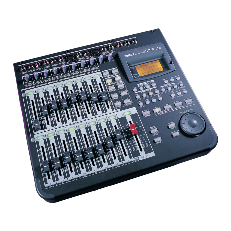
Fostex VF-16 Owner's Manual
Digital multitracker
Hide thumbs
Also See for VF-16:
- Supplement owner's manual (16 pages) ,
- Specifications (4 pages) ,
- Quick start (2 pages)
Table of Contents
Advertisement
Quick Links
1/9/A
2/10/B
3/11/C
4/12/D
5/13/E
6/14/F
TRIM
LINE
MIC
LINE
MIC
LINE
MIC
LINE
MIC
LINE
PEAK
PEAK
PEAK
PEAK
1/9/A
2/10/B
3/11/C
4/12/D
5/13/E
CH STATUS
ORANGE
INPUT
RED
REC
CH STATUS/CH SEL
+6
+6
+6
+6
+6
0
0
0
0
0
-10
-10
-10
-10
-10
-20
-20
-20
-20
-20
-30
-30
-30
-30
-30
-40
-40
-40
-40
-40
-
-
-
-
-
1
2
3
4
CH STATUS/CH SEL
+6
+6
+6
+6
+6
0
0
0
0
0
-10
-10
-10
-10
-10
-20
-20
-20
-20
-20
-30
-30
-30
-30
-30
-40
-40
-40
-40
-40
-
-
-
-
-
9
10
11
12
A
B
C
D
Owner's Manual
Digital Multitracker
INPUT
7/15/G
BAL
UNBAL
INSERT
BAL
MON OUT
MIC
LINE
MIC
LINE
MIC
LINE
MIC
0
10
PEAK
PEAK
PEAK
PEAK
6/14/F
7/15/G
8/16/H
GREEN
PLAY
OFF
MUTE
SCENE
RECALL
D I R E C T R C L
CLEAR
EFF EDIT
EFF1
+6
+6
+6
MUTE
CH PARAM EDIT
0
0
0
EFF1/EFF2
PRE/POST
-10
-10
-10
AUX1/AUX2
-20
-20
-20
PRE/POST
-30
-30
-30
-40
-40
-40
PAN
-
-
-
FADER
5
6
7
8
TRACK
+6
+6
+6
+6
0
0
0
0
-10
-10
-10
-10
-20
-20
-20
-20
-30
-30
-30
-30
-40
-40
-40
-40
-
-
-
-
13
14
15
16
TRACK
MASTER
E
F
G
H
INPUT
MON OUT
PHONES
8/16/H
L
R
UNBAL
INSERT
PHONES
DIGITAL
0
10
MULTITRACKER
STORE
OPTICAL
MAP
EFF2
ACCESS
MUTE
PHANTOM
EQ/COMP
HI-G/F/Q
COMP
REC ASSIGN
BUSS
DIRECT
INPUT SEL
SOURCE
REC TRK
REC TRK
MID-G/F/Q
AUTO RTN
AUTO PUNCH
START
IN
OUT
END
LO-G
1
2
3
4
MARK
CH VIEW
UNDO/
HOLD/
STORE
EDIT
REDO
RECORD
STOP
PLAY
CLIPBOARD PLAY
AUTO PUNCH
L O C AT E A B S
0
LOCATE REC END
FADER
ADJUST
EXIT/NO
EJECT
LEVEL
ADJUST
ENTER/YES
SHIFT
8288 451 100
DISP SEL
PGM SEL
SETUP
TIME BASE
CLIPBOARD
A RTN
IN
ALIGN SEL
OUT
A PLAY
5
6
7
SCENE SEQ.
VARI
PITCH
LOCATE
SCRUB
P .EDIT
EVT MEM
REWIND
F FWD
PREV
NEXT
JOG
SHUTTLE
Advertisement
Chapters
Table of Contents

Related Manuals for Fostex VF-16


Summary of Contents for Fostex VF-16
- Page 1 Owner’s Manual Digital Multitracker INPUT 1/9/A 2/10/B 3/11/C 4/12/D 5/13/E 6/14/F 7/15/G TRIM LINE LINE LINE LINE LINE LINE LINE PEAK PEAK PEAK PEAK PEAK PEAK 1/9/A 2/10/B 3/11/C 4/12/D 5/13/E 6/14/F CH STATUS ORANGE INPUT GREEN PLAY CH STATUS/CH SEL CH STATUS/CH SEL MON OUT 8/16/H...
-
Page 2: Safety Instructions
CAUTION RISK OF ELECTRIC SHOCK DO NOT OPEN CAUTION: TO REDUCE THE RISK OF ELECTRIC SHOCK, DO NOT REMOVE COVER (OR BACK). NO USER - SERVICEABLE PARTS INSIDE. REFER SERVICING TO QUALIFIED SERVICE PERSONNEL. "WARNING" "TO REDUCE THE RISK OF FIRE OR ELECTRIC SHOCK, DO NOT EXPOSE THIS APPLIANCE TO RAIN OR MOISTURE."... -
Page 3: Precautions
(such as an air conditioning system or large electric heater) are connected. * If you use the VF-16 in an area with a different power voltage, first consult your dealer or the nearest Fostex service station. You can use the VF-16 with a power frequency of 50Hz or 60Hz. -
Page 4: Table Of Contents
Safety Instructions ... 2 Precautions ... 3 Chapter 1 Basic Features of VF-16 Introduction ... 6 Product Features ... 6 Before Operating ... 7 Two RECORDING Modes ... 7 RECORDING System ... 9 PROGRAM ... 9 REMAIN Indicator ... 9 CHANNEL and TRACK ... - Page 5 Variable Pitch Control ON/OFF ... 59 Setting the Speed ... 59 Auto Function ... 60 Auto Play ... 60 Auto Return ... 60 Set (Store) Start/End Point ... 60 Auto Repeat ... 60 Program ... 61 Creating a New Program ... 61 Selecting a Program ...
-
Page 6: Chapter 1 Basic Features Of
Chapter 1 Basic Features of VF-16 Introduction Congratulations! You have chosen a truly unique multitracking device. The VF-16 Fostex Digital Multitracker features a myriad of high-tech functions. These include a digital mixer incorporates high-performance DSP multi- effect made possible using the Fostex-original A.S.P. -
Page 7: Before Operating
Before Operating This section defines the contents, names and terms the user should know prior to actually operating the VF-16. Please read the overview before going any farther with your new recorder as it will save you a lot of time in the long run. - Page 8 The keys below play important roles when executing DIRECT recording or BUSS recording. Please learn their functions before operating the VF-16. [INPUT SEL] key This key is used to determine whether signals to be input to tracks Ch1-Ch16 should be the recorder out- put (TRACK) or the input signal (INPUT).
-
Page 9: Recording System
ABS time. Note that it is also possible to move (locate) to any point within that time range, as well. Just think of the VF-16 as coming with a tape that is pre-programmed with a 24 hour counter. -
Page 10: Input Monitoring And Playback Monitoring
(procedures described later) in such case. The following are specific examples of the number of events. A. The VF-16 counts the silent portion of a silent track, which is counted as one file, but not recorded with any sound. Track 17 Therefore, this means that there will be one file on the track. -
Page 11: Fader
FADER The VF-16 features 16 channel faders and 1 master fader. Among the faders, the faders for channels 1 to 8 are always started up with output signals from the recorder of tracks 1 to 8 (PLAYBACK or INPUT Monitoring) to adjust this level. The master fader is always used to adjust the output level of the stereo output. -
Page 12: Time Base
BAR/BEAT/CLK indicate the “Bar, Beat, Clock” that are created with the tempo map (beat and tempo) of the VF-16. According to the following figure, the recorder is located at -002BAR (Bar 2) 1BEAT (Beat 1) of the BAR/ BEAT/CLK. -
Page 13: Names And Functions
Names and Functions 1/9/A 2/10/B 3/11/C 4/12/D 5/13/E TRIM LINE LINE LINE LINE PEAK PEAK PEAK PEAK 1/9/A 2/10/B 3/11/C 4/12/D CH STATUS ORANGE INPUT CH STATUS/CH SEL CH STATUS/CH SEL WARNING: CAUTION RISK OF ELECTRIC SHOCK TO REDUCE THE RISK OF FIRE OR ELECTRIC DO NOT OPEN SHOCK, DO NOT EXPOSE THIS EQUIPMENT AVIS:... -
Page 14: Top Panel
Top Panel Analog Input/Output Section 1/9/A 2/10/B 3/11/C 4/12/D 5/13/E LINE LINE LINE LINE PEAK PEAK PEAK PEAK 1/9/A 2/10/B 3/11/C 4/12/D 1. [INPUT] (Unbalanced) Jack: A to F * This adjusts the unbalanced output of the external sound source. * Standard Input Level: -50dBV to + 2dBV * Connector: Phones jack 2. -
Page 15: Mixer Section
Mixer Section CH STATUS ORANGE 11. [CH STATUS/CH SEL] Key: channels 1-16 * ON/OFF key for each channel during normal display (explained later). * Select the channel to CHECK/CHANGE the setting with ([CH PARAM EDIT] Key (No. 17-22) when CHECKING/ CHANGING various PAN, equalizer and other mixer parameters. - Page 16 15. [EFF EDIT-EFF1/MUTE] Key * This is used to CHECK/CHANGE the EFFECT type and parameter settings of EFFECT 1. * Press this key while the [SHIFT] key is depressed to turn ON/OFF the mute feature of EFFECT 1. 16. [EFF EDIT-EFF2/MUTE] Key * This is used to CHECK/CHANGE the effect type and parameter settings of EFFECT 2.
-
Page 17: Recorder Section
Recorder Section 25 26 27 28 INPUT SEL HOLD/ 25. [INPUT SEL] Key * Set whether to send the A to H input signals [INPUT] or track 9-16 play [TRACK] sounds to the faders of channel faders 9 to 16. 26. - Page 18 32. [AUTO RTN-START/MARK1] Key * This key is used to CHECK/CHANGE the parameters saved at the start point (AUTO RETURN START POINT) when executing auto return or auto repeat. * Press this key while the [SHIFT] key is depressed to CHECK/CHANGE the parameters saved in [MARK1].
- Page 19 46. [SCRUB] Key * This is used to digitally scrub sounds in the FWD and REV direction without any change in pitch. 47. [RECORD/AUTO PUNCH] Key * Press the [PLAY] key while this key is depressed (or press this key while the [PLAY] key is depressed) to start recording the READY track.
-
Page 20: Display Section
* Connector: Half pitch D-sub, 50-pin, female 69. [POWER] switch * This turns ON/OFF the power of the VF-16. 70. [AC IN] Jack * This is where the accessory power cable is inserted. For more details, refer to the respective instructions of each item. -
Page 21: About The Hard Disk Storage Device
About the hard disk storage device The VF-16 is complete with a 3.5-inch E-IDE hard disk (storage device) which is formatted in the Master 16 mode. Therefore, there is no need to newly assemble a hard disk or to format the hard disk. The user can immediately start recording with the VF-16. -
Page 22: Replacing A Hard Disk
<Precautions Upon Replacement> * Always turn OFF the power of the VF-16 and unplug the power plug from the electric outlet when replacing the hard disk. - Page 23 1. Unscrew the four screws from the bottom of the main unit that are fixing the panel. 2. Turn over the panel that the hard disk is fixed according to the instructions shown in the figure below. Note that hard disk cables will be connected. Be careful not to apply excessive force when turning over the panel.
-
Page 24: Formatting The New Hard Disk
Formatting the Hard disk Carefully follow the instructions below to newly format the hard disk properly. 1. Turn ON the VF-16 after plugging the power cable in the electric outlet. The VF-16 will startup. “Unformat!” will appear on the LCD. The menu will automatically go to the SETUP mode. -
Page 25: Chapter 2 Basic Recording And Playback
Chapter 2 Basic Recording and Playback Connections of Peripheral Equipment The VF-16 is equipped with input/output jacks to connect the following sound sources and external equipment. Always turn the [MASTER] fader, [MON OUT] knob and [PHONES] knob to “0” when connecting the external equipment to the input/output jacks. -
Page 26: Menu Shown When Turning Power On
The follwing describes the contents shown on the LCD and their operations. Menu shown when turning power ON When the VF-16 is turned ON with a hard disk already formatted, the following menu will appear in order: [Initial... (Initializing)] & [Version] -> [Current Dr] ->... -
Page 27: Switching With [Disp Sel] Key
The icon shown here is indicating that it is presently set “Off” and thus recording is possible. This is indicating the VF-16 sampling frequency (Fixed to 44.1kHz). This indicates the drive setup by the “Drive Sel” menu. The icon here is indicating that it is set to an “E-IDE... -
Page 28: Instructions To Direct Record
Hints and tips to successfully operate the VF-16 are included according to the workflow, ranging from the actual recording to mix down process. Both experienced and novice users of multitracker should try this process so as to learn the VF- 16 operations. -
Page 29: Preparing To Record
3. Press the [STOP] key to stop the recording operations. The LCD will show a “Please Wait” message and then return to the Normal Display. This completes the process to record on track 1. Check the sound recorded using the following procedures. PLAY 1. -
Page 30: Direct Recording
DIRECT Recording After reading the instructions up to this point, you are probably aware that the track recorded varies according to the input channel. With DIRECT Recording, the relationship between the channel input and track recorded are as follows. Connect to [INPUT] 1/9/A: Recordable on track 1/9. Connect to [INPUT] 2/10/B: Recordable on track 2/10. -
Page 31: Saving On The Memory Key And Mark Key
Saving on the Memory key and Mark key 1. Ensure the system is in the PLAY or STOP status. Press the [HOLD/>] key at the time to save. The time is held on the LCD at the point the [HOLD/>] key is pressed. -
Page 32: Locating An Event Memory
Scene event map described later in “Chapter 3. Advanced mixer operations.” Creating an event memory 1. At the desired position while the VF-16 is stopped or during playback, press the [HOLD/>] key. The time when pressing the [HOLD/>] key is held on the screen. -
Page 33: Punch In/Out
REC to PLAY. The time to punch in is called the PUNCH IN point, and the time to punch out is called the PUNCH OUT point. The VF-16 features the following 3 types of PUNCH IN/OUT modes. -
Page 34: Track Exchange
This feature is convenient to use when recording with all G and H [INPUT] jacks that can be connected with a condenser mic or balanced output, for example. Note that the VF-16 comes with 16 tracks, plus 8 additional tracks. The Track Exchange feature makes it possible to exchange these tracks with any unneeded tracks 1-16. -
Page 35: Equalizer Adjustment
2. Press the [CH STATUS/CH SEL] key of the channel intended for PAN adjustment. The channel selected flashes, then the input signal and the current setting of the channel selected appears on the LCD. 3. Turn the [JOG] dial to set the PAN level. A graphic display of the PAN parameter appears on the LCD in real-time. -
Page 36: Mix Down
Create the master tape after adjusting all tracks. Start recording the piece with a master recorder (cassette tape, DAT, MD, etc.). The VF-16 can output S/P DIF (optical) digital signals making it is possible to directly mix down digital signals if the master recorder can input S/P DIF (optical) digital signals. -
Page 37: Instructions To Record With Buss Record
Instructions for recording with BUSS RECORD This section will discuss the basic procedures to REC/PLAY with "BUSS" RECORD, which is another recording option. With DIRECT RECORD, the track recorded was determined according to the input of channel A to H. However, with BUSS RECORD, recording is possible regardless of the channel input. - Page 38 4. Press the [BUSS-SOURCE] key (GREEN: Flashing). The display to select the source channel sent to REC BUSS appears. 5. Press the [CH STATUS/CH SEL] key of ch16 (ORANGE: Flashing). The signals of input H started with the fader of ch16 is sent to REC BUSS.
-
Page 39: Recording 8 Inputs To Tracks 7 And 8
The source channel PAN can be optionally set ONLY when there are two REC tracks set. Recording 1. Locate the time to start recording on the VF-16. 2. Press the [PLAY] key while the [RECORD] key is depressed to start recording. - Page 40 The system is ready to record after you have com- pleted the above procedures. Record 1. Locate the time to record on the VF-16. 2. Press the [PLAY] key while the [RECORD] key is depressed to start recording. The [CH STATUS/CH SEL] key and the [RECORD] key of ch7&8 lights up RED, indicating that recording is taking...
-
Page 41: Chapter 3 Advanced Mixer Operations
Initial condition when the power is turned on When you turn the power on, the VF-16 shows the start-up display ("FOSTEX" -> "Initial.." -> "Current DR", "IDE" -> "Format Type" ["Standard" or "Quick"]), and then becomes ready. In this condition, only the [CH STATUS/CH SEL] key, [STOP] key, [EFF 1] key, and [EFF 2] key light on the panel, while the display looks as shown below. -
Page 42: Channel Parameter Edit
[JOG] dial. 4. To set another channel's pan, repeat steps 2 and 3 above. flashing 5. After completing pan editing, press the [EXIT/NO] key. The VF-16 exits the channel edit mode and the display returns to the Normal display. EQ/COMP HI-G/F/Q... -
Page 43: Adjusting Eq
ON/OFF: 4. To edit the EQ for another channel, repeat step 1 through 5. After completing EQ editing, press the [EXIT/NO] key. The VF-16 exits the EQ edit mode and the display returns to the Normal display. curve -18 dB to FLAT to +18 dB (default: FLAT) 500 Hz to 20.2 kHz (default: 4.00... -
Page 44: Controlling Effect Send Level
3 above. 5. After completing send level editing, press the [EXIT/NO] key. The VF-16 exits the channel edit mode and the display returns to the Normal display. Selecting pre/post of Effect sends You can select whether the pre-fader or post-fader signal is sent from each channel (1 to 16) to the effect processor. -
Page 45: Controlling Aux Send Level
2 and 3 above. 5. After completing the pre/post selection, press the [EXIT/ NO] key. The VF-16 exits the channel edit mode and the display returns to the Normal display. Controlling AUX SEND level You can control send levels of channels 1 through 16 (pre- or post-fader) from the AUX SEND jack on the rear panel. -
Page 46: Controlling Fader Levels
5. After completing the pre/post selection, press the [EXIT/ NO] key. The VF-16 exits the channel edit mode and the display returns to the Normal display. Controlling fader levels You can control fader levels for channels 1 through 16 and the master channel while viewing the numeric values. -
Page 47: Channel View
The screen example above shows the following status. 3. To turn off the channel view screen, press the [EXIT/NO] key. The VF-16 exits the channel edit mode and the display returns to the Normal display. Channel 1 is currently selected. -
Page 48: Effect Edit Mode
Effect Edit Mode The VF-16 offers high quality ambient effects by employing the A. S. P. (Fostex Advanced Signal Processing Technology), which is exclusively developed by Fostex. With the A. S. P., you can obtain an incomparably clean and high density Hall Reverb, overwhelmingly clear Room Reverb and wonderfully hi-fidelity Plate Reverb. -
Page 49: About The Effect Types
About the effect types The VF-16 contains two independent DSP multi-effect units; EFF 1 and EFF 2. A variety of effect types are preset for each effect unit. By selecting a suitable effect type, you can process the sound as you wish. You can also edit the parameters of the selected effect type to create your own effect sounds. -
Page 50: Selecting The Effect Type
Effect types preset for EFF 2 Name Parameter type 1~28 are the same effect types as the EFF 1 presets listed on the preceding page. (For details refer to the preceding page.) L29 MonoDELAY DELAY L30 PanDELAY DELAY L31 MonoBpmDL BPM DELAY L32 PanBpmDL BPM DELAY... -
Page 51: Effect Parameter Settings
Effect parameter settings Here's how to set the effect parameters. 1. If the effect parameter that you wish to adjust is not displayed, press the [EFF 1] key (or the [EFF 2] key) twice. One of the parameters of that effect type will appear. 2. - Page 52 BPM delay effect parameters (parameter type: BPM DELAY) For effect types 31 and 32 of the preceding "Effect type" table, the following four parameters can be adjusted. 1. Eff Level Adjust the effect return level: 0~99 2. BPM Adjust the BPM. Range: 30--250 bpm 3.
-
Page 53: Scene Memory
Scene memory The VF-16 provides 100 scene memories (Scene numbers 00 to 99). You can store a set of desired parameter settings to each memory. Items to be stored include all parameters set by the channel parameter edit and effect edit modes, as well as all channel fader levels. -
Page 54: Level Adjust
Level adjust When recalling a scene memory, if the recalled fader level does not match the current physical fader posi- tion (the red indicator of the [FADER ADJUST] key flashes), you can adjust the level to match the current fader position. 1. -
Page 55: Direct Recall Of A Scene Memory
You can create up to 99 event memories (01 to 99). Creating an event memory on the fly 1. At the desired position while the VF-16 is stopped or during playback, press the [HOLD/>] key. The time when pressing the [HOLD/>] key is held. -
Page 56: Creating The Scene Event Map
The event memories created in real-time by the proce- dure described above can be viewed by the operation below. 1. While the VF-16 is stopped, press the [SCENE STORE/ MAP] key while holding down the [SHIFT] key. The screen shows the event memory list as below, in which you can view and check the event memories created in real-time. -
Page 57: Deleting An Event Memory
1. While the VF-16 is stopped, press the [A RTN A PLAY/ SCENE SEQ] key while holding down the [SHIFT] key. After "SCENE SQ: ON" is briefly shown on the screen, the Normal display appears. -
Page 58: Chapter 4 Recorder Functions
Chapter 4 Recorder Functions Cueing This section describes the cueing feature for cueing sound during the F FWD or REWIND process. Cueing with the [F FWD]/[REWIND] key The user can cue at 3x speed by pressing the [F FWD]/ [REWIND] key while the recorder is playing. 1. -
Page 59: Variable Pitch Control
This section describes the Variable Pitch Control feature to play or record programs at variable recorder speeds. The VF-16 can change the speed in 0.1% units within a +/-6.0% range. Note that the key changes when changing the variable pitch speed. -
Page 60: Auto Function
Auto Function The VF-16 is equipped with 3 Auto Functions. One is the “Auto Play”, which automatically starts playing a track after locating it. Another is the “Auto Return”, which locates a predetermined time during playback. The third, “Auto Repeat”, combines the former two features to repeat playing a certain segment. -
Page 61: Program
Program With the VF-16, the music is managed according to programs numbered 01-99 (99 programs). These programs are independent of each other and can be recorded or played separately. This section describes the instructions of how to operate the program. -
Page 62: Selecting A Program
If there are several programs set on the disk, there may be a need to select a target program. The following instructions are based on the VF-16 in the STOP status in the Normal Display. 1. Press the [PGM SEL] key in the STOP state. -
Page 63: Editing The Track
Editing the Track The VF-16 features a 3.5 inch E-IDE hard disk as a storage media. This allows speedy voice editing in a nonlinear and nondestructive manner in track units. There are four track editing options as described below. -
Page 64: Copy & Paste And Move & Paste
Copy & Paste and Move & Paste This section describes the Copy & Paste (or Move & Paste) details. <Precaution> * The data copied (or moved) on the clipboard is replaced with new data every time data is copied (or moved). -
Page 65: Undo/Redo Paste
To align the head of the measure for pasting together with sound data in front of the measure, the “ALIGN SEL” function of VF-16 can be utilized. To use this function, the head of the measure data in the clip data must be registered in the [ALIGN SEL] key as shown in Figure 3. -
Page 66: Erase
Erase The VF-16 provides the following “ERASE” options. Please read the instructions in its entirety prior to actual operations, to prevent any erroneous understanding of the description. First, start the desired program if there are several programs set. DO NOT change a program in the middle of the erase procedure. -
Page 67: Undo/Redo Erase
4. Press the [ENTER/YES] key. “Sure?” flashes. 5. Press the [ENTER/YES] key once again. The erase process will takes place. “Wait Erasing!” flashes on the display while data is being erased. “Completed!” lights up on the display when the data is successfully erased. - Page 68 3. Press the [ENTER/YES] key. The tracks are instantly exchanged. “Completed!” appears on the display when the tracks are successfully exchanged. Then the LCD returns to the original time base display. When exchanging mono tracks. 1. Turn the [JOG] dial while “1-8” is flashing. By turning the [JOG] dial to the left and right it is possible to select the mono track numbers “1”, “2”, “3”, “4”...”24"...
-
Page 69: Chapter 5 Features Application
Chapter 5 Features Application Applications of DIRECT RECORD This section describes applications of the DIRECT RECORD feature. DIRECT RECORD while listening to the input signal DIRECT RECORD basically takes place with the play [TRACK] started for all the channel faders. However, it is also possible to start [INPUT] signals A to H. -
Page 70: Applications Of Buss Record
Applications of BUSS RECORD BUSS RECORD makes it possible to record all the source channel signals sent to REC BUSS L/R on either 2 tracks or 1 track. The source channel is selectable with the “INPUT” channel and “TRACK” channel, therefore, it is pos- sible to record the input signals along with signals that are already recorded. -
Page 71: Ping-Pong Record
Ping-Pong RECORD By using BUSS RECORD, it is possible to select a maximum of 15 source channels when recording to 1 track and a maximum of 14 source channels when recording to 2 tracks. Here we will ping-pong record the sound recorded on tracks 1-14 onto tracks 15 and 16 for temporary mix down. -
Page 72: Metronome Function
Metronome Function The VF-16 incorporates a tempo map to set a desired bar/beat (4/4, 3/4, etc.) and tempo (30-250). It is possible to output a metronome sound, according to the setting of the tempo map. This allows for recording in sync with the rhythm output from the VF-16 without having to use an external metronome or rhythm box. -
Page 73: Digital Recording
Digital Recording This section will describe digitally recording from the VF-16 to external digital devices or to digitally record from external digital devices that are connected to the [DATA IN]/[DATA OUT] jack of the VF-16. Digital signals recorded are either S/P DIF or adat digital signals. -
Page 74: Selecting A Track To Record
"0". 2. Press the [PLAY] key while the [RECORD] key is depressed to start recording with VF-16, as well as start playing the external digital device. The level meter of the digital signal level that is currently input will appear. -
Page 75: Midi Clock Sync System
MIDI clock and song position pointer according to the setting, a hardware type MIDI sequencer can be synchronized as a MIDI clock slave. Consequently, in this system, the VF-16 will be the master and the MIDI sequencer the slave. -
Page 76: Connecting External Equipment
(absolute time) and output it as MTC in any desired frame rate. It can also carry out the proper operation upon receiving an MMC from outside. In this case, because the VF-16 can setup a DEVICE ID number by the SETUP mode “MIDI Device ID Setting”... -
Page 77: Connecting To External Equipment
For details, refer to Owners Manual of the external equipment. Setup of the VF-16 1. Because MTC will be output from the VF-16, set to “MTC” the SETUP mode “MIDI sync signal output setting.” Refer to page “103”, SETUP mode “MIDI sync signal output setting”... -
Page 78: External Midi Equipment Sync System By The Slave Mode
External MIDI equipment sync system by the slave mode Up to this point, synchronization with external MIDI equipment has been explained with the VF-16 as the master and MIDI equipment as the slave but depending on the slave mode setting, the MIDI equipment can be set as the master and the VF-16 as the slave. -
Page 79: Confirming Chase Lock
<One Point Advice> Sync signal “Vari” of the “Slave mode setting” menu: When the VF-16 is made to chase lock by MTC only, variable pitch will be constantly applied by external MTC. If a digital signal is output to an external digital... -
Page 80: Chapter 6 Save/Load Of Song Data
VF-16 via the adat digital signal, data is also transferred with eight- track data blocks, as with the same way as saving data from the VF-16 to an adat machine. (See also <Notes> on the next page.) - Page 81 <Notes for DAT and adat machines to be used> The VF-16 song data only can be saved to or loaded from a digital machine that can record 16 bit, 44.1 kHz linear digital data with S/PDIF or adat format (such as DAT and adat machines).
-
Page 82: Saving Data Using The S/Pdif Or Adat Digital Signal
• Do not connect digital signals for both directions between the VF-16 and the external device (i.e. the digital output of the VF-16 to the digital input of the external device and the digital output of the external device to the digital input of the VF-16), which may form a digital loop and cause feedback. - Page 83 After a few seconds, the unit starts saving the data and "Wait time" starts counting down. For the first several seconds, the VF-16 transmits the pilot signal that will a reference for locating the tape position during the load operation, and the actual data saving starts from the position at which "Wait time"...
-
Page 84: Loading Data Using The S/Pdif Or Adat Digital Signal
• Do not connect digital signals for both directions between the VF-16 and the external device (i.e. the digital output of the VF-16 to the digital input of the external device and the digital output of the external device to the digital input of the VF-16), which may form a digital loop and cause feedback. - Page 85 "Sure?" flashes. <Note> In the above step, if the VF-16 does not lock to the digital signal from the external digital device, the following warning message appears on the display.
-
Page 86: Saving/Loading Data Using Scsi
WEV file on a SCSI disk formatted by the DOS format (for computer use). Since song data written in a WAV file can be read by a computer, as well as can be loaded to the VF-16, you can use the data with a music software. - Page 87 Saving data to a SCSI disk You can save data via the "Save PGM" menu in the SETUP mode. When saving to a SCSI disk, you can save data for each specified program like saving to a DAT/adat. <Details about "Save PGM" menu> •Output signal options: adat, S/PDIF and SCSI •Program options: P01 to P99 (an individual Program)
- Page 88 [ENTER/YES] key. The disk will be ejected and "Insert Disk" will flash on the display. The screen above shows that the VF-16 is saving the song data of program 01 to B01 on the backup disk. The remaining data size shown on the screen counts down while the data save goes on.
- Page 89 • In the saving operation using more than one disk, if you use a disk in which save data is already recorded: When carrying out step 6 above, an existing program number is shown. In this condition, by using the [JOG] dial, you can select "Eject", as well as existing programs.
- Page 90 <Note> If Disk-2 (the second disk when saving) is inserted in mistake, the VF-16 automatically recognized that the wrong disk is set. The display shows "Wrong Disk", followed by "Illegal No!", and the disk is automatically ejected. Then, as the display shows "Insert Disk", insert Disk-1.
- Page 91 5. Insert Disk-2 (the second disk) to the SCSI device according to the display message. In a while after inserting the disk, the VF-16 automatically starts loading data from Disk-2. The screen looks similar to the one when loading Disk- 1.
-
Page 92: Save/Load A Wav File
Save/load a WAV file Song data can be saved to or load from a SCSI disk by the FDMS-3 (Fostex Disk Management System-3) format, as well as by the WAV file format (RIFF WAVE file format) using a DOS-formatted disk. As you can handle song... - Page 93 Saving a WAV file You can save a WAV file. Make sure that the DOS-formatted disk with FAT16 is set. The following procedure assumes that the newly formatted "clean" disk is used for backup. 1. Press the [SETUP] key to enter the Setup mode. The display shows the screen for selecting the Setup menu.
- Page 94 flashing <Hints> If the backup disk contains any existing program(s) previously saved, the display may show following screens after carrying out the previous step, depending on the available space of the backup disk. •Showing the title and "New File": There is enough space for creating a new WAV file in addition to the existing WAV files on...
- Page 95 "clean" disk for backup. • If any other file but "******##.WAV" or folder, which cannot be recognized by the VF-16, is created on the backup disk using a personal computer, the VF-16 cannot calculate the available backup disk space accurately.
- Page 96 5. After selecting the desired WAV file, press the [ENTER/ YES] key. The display shows the screen for selecting a track to be loaded. "All" flashes initially. Besides "All", you can select any one of tracks (01 through 24) by rotating the [JOG] dial. 6.
-
Page 97: Special Loading Method When Using A Computer
<< Special loading method when using a computer >> < Note> WAV files which can be saved/loaded by this recorder must have file names written as “******##.WAV.” Other file names cannot be acknowledged by this recorder. Unknown file names will not be acknowledged and could cause malfunction. Extreme care should be taken when changing file names and making folders on a computer. -
Page 98: Chapter 7 Setup Mode
The SETUP mode of the VF-16 offers the “Changing the initial settings” menus, which configure the operating environment of the VF-16, a “Check” menu that enables you to check the number of events for each track, and an “Execution” menu that executes certain operations, such as save and load and disk formatting. The “Changing the initial settings”... -
Page 99: To Enter The Setup Mode
For example, you can specify 4/4 for the first and second measures, and 2/2 from the third measure.” Setting a time signature and tempo will create a Tempo Map, which allows the VF-16 to manage a song using the BAR/BEAT/CLK Time Base. You can also use the Metronome function. -
Page 100: Correcting The Registered Time Signature
The following bar numbers and time signatures can be entered via the [JOG] dial. You can enter are from 001 to 999. Time 1/4, 2/4, 3/4, 4/4, 5/4, 1/8, 3/8, 5/8, 6/8, 7/8, 8/8 Signature or DEL “DEL” is used to deleted time signature data. 6. -
Page 101: Setting A Tempo
For example, you can specify a tempo of 150 to the third beat of the 12th measure. Time signature and tempo settings make a Tempo Map, which is used by the VF-16 to manage the song using the BAR/BEAT/CLK time base, and enable the metronome function. -
Page 102: Correction Of The Registered Tempo
(or [STOP] key) to exit from the SETUP mode. Setting the Metronome function [“Click”] “Setting the Metronome function” menu allows you to determine whether or not the VF-16 outputs a metronome sound from track 16 during playback or recording. Turning the Metronome function on enables you to record your performance while playing the instrument accompanying the metronome sound. -
Page 103: Setting A Preroll Value
Setting a preroll value [“Preroll Time”] The VF-16 features a Preroll function that enables you to locate a position a few seconds prior to a specified locate point. The “Setting a preroll value” menu enables you to set the preroll time (in seconds). -
Page 104: Setting An Mtc Frame Rate
The “Setting an MTC offset value” menu enables you to specify an offset time value - the difference between the time of MTC output from the VF-16 and the ABS 00m 00s 00f 00sf time. You need to specify this value if you have selected [MTC] for the “Setting MIDI sync output signal”... -
Page 105: Setting Mtc Offset Mode
* If you set Offset mode to “BAR“ and use MTC to synchronize sequence software on the computer, the tempo of the sequencer may sometimes slip gradually. This is because the tempo of the VF-16 and the tempo of the software are slightly different even if both use the same tempo. -
Page 106: Setting The Slave Type
If you have set Slave Mode to “On” in the previous section “Slave Mode Setting,” you can choose what type of external sync signal that the VF-16 synchronizes to. This mode allows you to choose the external sync signal type. -
Page 107: Setting Digital Input
If “S/P DIF” is selected for input of digital, the S/P DIF signal (L, R) applied to DIGITAL/DATA INPUT of VF-16, it will be assigned to any two tracks, and if “adat” is selected, the adat signals will be assigned to tracks 1 through 8. -
Page 108: Setting Digital Output
CLIPBOARD IN/OUT points and other points in real-time. (Press the [STORE] key, then the corresponding memory key while playing the VF-16.) Therefore, it is very convenient when you perform the Copy & Paste or Move & Paste operation in beat-resolution. -
Page 109: Setting The Midi Device Number
The transmit device ID links to this setting. You can set the device ID from 00 to 99. However, if the device ID number of the message the VF-16 receives is [7F], the VF-16 will recognizes it to perform the corresponding operation, regardless of its device ID setting. -
Page 110: The Drive Format Information
* Editing a title If power to the VF-16 is switched again, the drive will automatically switch to current drive (E-IDE). In order to take out the removable disk when set to backup drive, press the [EXIT/NO] key while holding down the [SHIFT] key. -
Page 111: Fader Fix Mode Setting
* The settings cannot be saved and loaded as part of the song data. * The settings are maintained after you turn off the power to the VF-16. 1. Select “Fader Fix” in the menu selection display and press the [ENTER/YES] key. -
Page 112: On/Off Of Phantom Power Setting
Compressor Channel Setting [“Comp. Channel”] In the "Setup of the compressor channel" menu, the channel in which the VF-16 internal compressor function should be activated can be setup. The compressor can be made to function in channels 13-14 or 15-16. - Page 113 <Important> EQ cannot be applied to the channel (Except the mas- ter channel) setup for the compressor. With the compressor channel setup, if the EQ editing mode is entered, this condition will be indicated by the [CH STATUS/CH SEL] key LED. The channel in which the LED (green) is blinking is an indication that EQ editing is possible in this channel and the channel in which the LED is not lit is an indi-...
-
Page 114: Trouble Shooting
A breakdown? If you suspect so, please read the fpllowing explanations before requesting repairs. * Input signal not indicated by the level meter ? Level meter does not light up even though recording track is set and channel fader/master fader is raised to the "0" position. Set the recorder to input monitor Press the [RECORD] key only. -
Page 115: Having Trouble Editing
Record digital signals of sampling frequency iden- tical to that of the VF-16 The VF-16 sampling frequency is 44.1kHz/16 bit. In a sampling frequency other than 44.1kHz/16 bit, it will be recorded with the wrong pitch. Time count will also be incorrect. -
Page 116: Midi Implementation Chart
(Digital Multitracker) Model VF-16 Function... Basic Default Channel Changed Default Mode Message Altered Note Number: True Voice Velocity Note ON Note OFF After Key’s Touch Channel’s Pitch Bend Control Change Program Change True # System Exclusive : Quarter Frame : Song Position... -
Page 117: Mmc Command List
IDENTITY REPLY: F0, 7E, <channel>, 06, 02, 51, 01, 00, 13, 00, **, **, **, **, F7 :Fostex ID 01, 00 :Device family code 13, 00 :Device family number VF-16 **, **, **, ** :Software version Movement (Recorder) STOP PLAY... -
Page 118: Maintenance
Cleaning the exterior * For normal cleaning, use a soft dry cloth. For stubborn dirt, moisten a cloth in diluted detergent, wring it out firmly, and wipe the dirt off. Then polish with a dry cloth. Never use solvents such as alcohol, thinner or benzene, since these will damage the printing and finish of the exterior. - Page 119 General Connector Weight Power Supply Power Consumption Accessories * Fostex Disk Management System-3 ** Fostex Data In Out-1 Specifications and appearance are subject to change without notice for product improvement. “Adat” an the symbol are trademarks of Alesis Corporation. -10dBV...
-
Page 120: Block Diagram
PEAK INPUT A (+4 ~ -50dBV) PEAK TRIM INPUT B (+4 ~ -50dBV) TRIM PEAK INPUT C (+4 ~ -50dBV) PEAK TRIM INPUT D (+4 ~ -50dBV) TRIM PEAK INPUT E (+4 ~ -50dBV) PEAK TRIM INPUT F (+4 ~ -50dBV) +48V TRIM PHANTOM... -
Page 121: Declaration Of Ec Directive
FOSTEX DISTRIBUTORS LIST IN EUROPE * Including non-EU countries. * underlined: contracted distributors (as of April, 1999) <AUSTRIA>... - Page 122 FOSTEX CORPORATION 3-2-35, Musashino, Akishima-shi, Tokyo, Japan 196-0021 FOSTEX CORPORATION OF AMERICA 15431, Blackburn Ave., Norwalk, CA 90650, U. S. A. © PRINTED IN JAPAN MAY 2000 8288 451 100 FX...
Need help?
Do you have a question about the VF-16 and is the answer not in the manual?
Questions and answers