Table of Contents
Advertisement
Owner's Manual
Model
Digital Multitrack Recorder
OPTICAL
ACCESS
OL
0
6
12
24
1
2
3
4
5
6
7
8
RECORD TRACK
1
2
3
4
AUTO RTN
AUTO PUNCH
START
IN
OUT
END
PREVIEW
HOLD/
EDIT
STORE
UNDO / REDO
PGM SEL
AUTO RTN
VARI PITCH
AUTO PLAY
LOCATE
SHIFT
P.EDIT
LOC MEM
RECORD
STOP
PLAY
CLIPBOARD PLAY
AUTO
PUNCH
LOCATE
ABS
0
LOCATE REC END
A SYNC
5
6
7
8
CLIPBOARD
EXIT
EXECUTE
/ NO
/ YES
IN
OUT
EJECT
DISP SEL
SETUP
JOG
TIME BASE SEL
SCRUB
SHUTTLE
REW
F FWD
8288 429 000
Advertisement
Table of Contents

Related Manuals for Fostex VR800


Summary of Contents for Fostex VR800
- Page 1 Owner’s Manual Model Digital Multitrack Recorder OPTICAL ACCESS A SYNC RECORD TRACK AUTO RTN CLIPBOARD AUTO PUNCH START PREVIEW HOLD/ EDIT DISP SEL SETUP STORE UNDO / REDO PGM SEL AUTO RTN VARI PITCH AUTO PLAY LOCATE TIME BASE SEL SCRUB SHIFT P.EDIT...
-
Page 2: Safety Instructions
CAUTION RISK OF ELECTRIC SHOCK DO NOT OPEN CAUTION: TO REDUCE THE RISK OF ELECTRIC SHOCK, DO NOT REMOVE COVER (OR BACK). NO USER - SERVICEABLE PARTS INSIDE. REFER SERVICING TO QUALIFIED SERVICE PERSONNEL. "WARNING" "TO REDUCE THE RISK OF FIRE OR ELECTRIC SHOCK, DO NOT EXPOSE THIS APPLIANCE TO RAIN OR MOISTURE."... -
Page 3: Table Of Contents
Introduction...5 Main features...5 Precautions...6 Note on repair...6 About copyrights...6 About damage...6 Names and Functions...7 Top panel...8 Rear panel...14 Side panel...15 Display section...16 Display when the power is turned on...16 Preset display...16 Display examples for time base selected via the TIME BASE SEL key...17 Selecting time base using the DISP SEL key...17 The REMAIN display...18 Warning message...19... - Page 4 Setting BAR/BEAT resolution mode...103 Setting the MIDI device number...104 Checking the number of each track events...105 MIDI Implementation Chart...106 MMC Command List/Inquiry Message List...107 Fostex System Exclusive Message...108 Status Request...109 Data Type...111 Explanation on the command/mode list...113 The status request command...115 Explanation on the status reply...116...
-
Page 5: Introduction
You can set up a synchronization system with a sequencer or a rhythm machine without wasting a track. • You can use the VR800 as a sync slave machine by sending MTC from a connected device. • The VR800 supports MTC, MMC, and Fostex System Exclusive Message, which allows for advanced control and high- precision synchronization from external sequencing software. -
Page 6: Precautions
Specifications section of this Owner’s Manual. Do not use an AC outlet of any other voltage. • Do not connect the VR800 to the same AC outlet to which devices that could generate noise (such as a large motor or... -
Page 7: Names And Functions
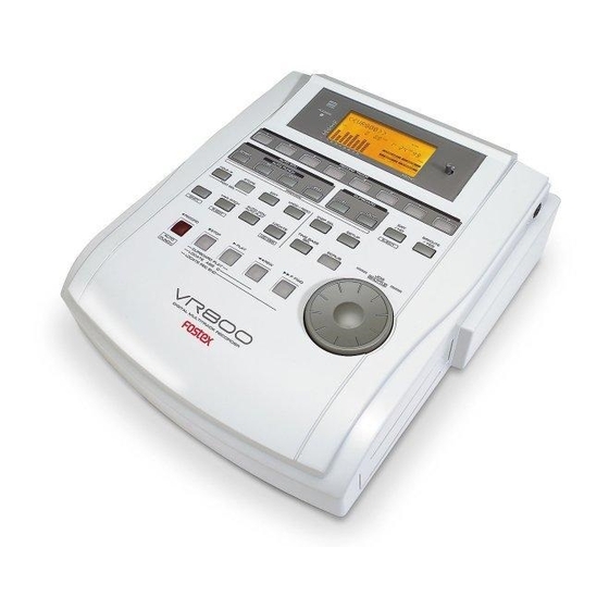
Names and Functions Rear panel DATA MIDI WORD OUT SCSI OPTICAL Top panel OPTICAL ACCESS RECORD TRACK AUTO RTN AUTO PUNCH START PREVIEW HOLD/ EDIT UNDO / REDO DISP SEL STORE PGM SEL AUTO RTN VARI PITCH AUTO PLAY LOCATE TIME BASE SEL SHIFT P.EDIT... -
Page 8: Top Panel
Refer to page 24 for more information on playback monitoring and input monitoring. Note: Do not turn off the power to the VR800 when this LED lights up or flashes. Otherwise you may lose data on the hard disk connected to the VR800. - Page 9 (ABS, MTC, or BAR/BEAT/CLK). The space indication uses MB (Megabyte). (The values are based on mono track recording.) *3 MTC being input from an external MIDI device to the VR800 appears. If no MTC is input, the display will show “00H 00M 00S 00F.”...
- Page 10 * Refer to page 66 for more information on Track Exchange. 13. JOG dial [JOG/ SHUTTLE When the VR800 is stopped, use the JOG dial to perform a jog operation (forward or reverse) for audio scrubbing without pitch change. You can also use this dial to increase and decrease the numeric values or input alphabetical characters in edit mode.
- Page 11 This mode is effective only when auto play mode and auto return mode are turned on. The VR800 will play the part between the AUTO RTN START point and the AUTO RTN END point repeatedly. This mode is also effective only if the AUTO RTN START point and the AUTO RTN END point have already been specified.
-
Page 12: Record Button
26. Hold/> key [HOLD/>] Pressing the HOLD/> key while the recorder is operating will cause the VR800 to capture the time when you pressed it (or bar/beat/clock value), display it, and then enter edit mode. (If you press the HOLD/> key while the recorder section is stopped, the VR800 enter edit mode directly.) - Page 13 -> CLK -> BAR. If you press the HOLD/> key and the STORE key simultaneously while the recorder is stopped, the VR800 will enter the program select mode, in which you can select a program or set up a new one.
-
Page 14: Rear Panel
This is also connected to the OPTICAL digital input (or adat in) of the external digital equipment in use when digital recording in external digital equipment (MD, DAT, CD-R, etc.) from the VR800 or when saving song data in external DAT or adat. DATA * Refer to the “Quick Operation Guide”... -
Page 15: Power Switch [Power]
7. AC IN connector The power cable packaged with this recorder ia connected here. 8. Power switch [POWER] This switch turns power on and off to the VR800. Side Panel (Connector: phone) Note: Always plug the power cable to the recorder before... -
Page 16: Display Section
The VR800 uses a liquid crystal display which integrates a 9-digit/35-dot message section, 7-segment display section, and level meters. The level meters indicate the output level of tracks 1-8. The time display shows various information in different units, such as ABS time (absolute time), MTC (MIDI timecode), BAR/ BEAT/CLK (bar/beat/clock), and makes it easy to check the recorder’s current time. -
Page 17: Display Examples For Time Base Selected Via The Time Base Sel Key
The default setting is [ASYnC] (indicator on). Note: If only a SCSI drive is connected to the VR800, [SCSI] lights up. If an 3.5-inch internal E-IDE hard disk has been installed but no external SCSI device is connected as the current drive, [IDE] lights up. -
Page 18: The Remain Display
Time base is BAR/BEAT/CLK. DIGITAL SYNC OUT AUTO DIGITAL REMAIN SYNC OUT AUTO DIGITAL MTC IN SYNC OUT AUTO Time base is MTC. DIGITAL SYNC OUT AUTO DIGITAL REMAIN SYNC OUT AUTO DIGITAL MTC IN SYNC OUT AUTO The REMAIN display The REMAIN display usually shows available recording space 44.1kHz and time on the disk, calculated based on mono track recording. -
Page 19: Warning Message
1. Leave the disk inside the SCSI drive and turn off the power to the VR800 and all connected devices. 2. Turn on the power to the SCSI drive. 3. Make sure that the orange LED on the SCSI drive lights up in green and that the disk is not being accessed. -
Page 20: Before Starting
(the current position). The VR800 offers three types of Time Base: ABS (Absolute type), MTC (MIDI time code), and BAR/BEAT/CLK (bar/ beat/clock). ABS indicates an absolute time on the disk. MTC indicates a relative time that is obtained by adding a certain value (MTC offset value) to the ABS value. -
Page 21: Recording Method And Remain Indicator
Recording method The VR800 uses a E-IDE hard disk, SCSI removable disk (such as an MO disk, zip disk etc.), or fixed disk instead of a cassette tape. You can start recording sound sources from any point on a formatted disk as long as the point is within the range of 24 hours in ABS time, as described in the previous “Time Base”... -
Page 22: Managing Songs By Program Change Function
As described in “Managing the song by Program,” the VR800 can set up as many as 99 Programs on the disk. Setting up a Program requires a small amount of disk space. In other words, disk space is used not only for storing recorded data but also for storing all setup data. -
Page 23: Real Tracks And Additional Tracks
Real tracks and Additional tracks The VR800 features eight Real tracks (1-8) and sixteen Additional tracks (9-24), for a total of twenty-four tracks. Real tracks are used to record sound sources in real-time. Additional tracks are used to temporarily store the sound recorded in the Real tracks. This is useful since you can move data from Real tracks to Additional tracks to clear tracks for fresh recording. -
Page 24: Input Monitoring And Playback Monitoring
Input monitoring means to monitor via track output the recording signal sent to the Real tracks of the recorder. That is, you are monitoring a post-recorder signal, not a pre-recorder signal. The VR800 enters input monitoring status when you perform one of the following operations. -
Page 25: Audio File And Event
During S/P DIF and adat digital recording, the VR800 records “data 0” (this is called “mute recording”). When one second of consecutive data 0 is input to the VR800, it creates a “0 file” and limits the consumption of disk space. However, repeating this operation will eventually increase the number of events, leading to “event number overflow.”... - Page 26 VR800 Owner’s Manual (Before Starting) Recorded Area 0 File Audio File 1 Audio File 2 Audio File 4 Audio File 6 0 File Audio File 3 Audio File 5 Event Number This is because when you perform a copy & paste, move & paste, or Auto Punch In/Out, the event is split at the edit point.
-
Page 27: Formatting A Disk
Set the ID number of a SCSI drive (fixed or removable) that will be used as a back-up disk to “6.” When you use the [Format ?] menu in SETUP mode, the VR800 recognizes SCSI drives or 3.5-inch E-IDE hard disks with any ID number other than “6.”... -
Page 28: Formatting A New Disk
Formatting a current drive disk (SCSI disk) The VR800 supports SCSI removable and fixed disks and 3.5-inch E-IDE hard disks as the current drive. This section explains how to format a SCSI removable (or fixed) disk. To format a SCSI disk, the [SCSI] indicator in the [DRIVE] section of the display should be lit. - Page 29 You need to use the [Format ?] menu in SETUP mode to reformat a disk. In the following procedure, we assume that a SCSI drive is connected to the VR800 and that the power to the VR800 and the SCSI drive is turned on. (The same procedure also applies to a fixed disk or 3.5-inch E-IDE hard disk.)
-
Page 30: Formatting The Current Drive (E-Ide Hard Disk)
SCSI ID number of the backup drive to “6” and format it in backup recording mode. The VR800 does not indicate the connected backup disk on the display (unlike the current drive). You need to use [Bk Format?] menu in SETUP mode to format a backup disk while the current drive is on. However, if the disk has not yet been formatted, you may format it during the save/load operation. -
Page 31: Formatting A Backup Disk (Fixed Disk)
However, you cannot perform another operation using the backup disk at this time. Attempting to do so will cause the VR800 to display [Viod Cmd! (Void Command!)] and ignore your operation. To eject the disk from the backup drive or the current drive after the format operation, follow the procedure below: * To eject a disk from the backup drive: Press the Eject button on the drive. -
Page 32: Handling Programs
AUTO PUNCH LOCATE LOCATE REC END 1. Turn on the power to the VR800 and a connected SCSI drive. 2. Insert a formatted disk into the SCSI drive. The VR800 will display [Initial..], [(SCSI drive name and ID number)], [(Recording mode, such as [ADAC 8ch])], then the top of ABS time base (ABS 0). -
Page 33: Using A Program Change Function
If multiple programs exist on the disk, you need to select a program to record, play, or edit. This section describes how to select a program. Note: You cannot use the program change function if the VR800 is in SETUP mode. OPTICAL... -
Page 34: Deleting A Program
To cancel the delete operation, press the EXIT/NO key while [SURE ?] is flashing. Each time you press the button or key, the VR800 will return to a higher level in the hierarchy, and finally exit the SETUP mode. When the VR800 displays [Deleting...] and finishes deleting the program, the data of the next program number moves in, and its ABS time appears. -
Page 35: Editing A Program Title
Note: You can edit the title of the selected program before you select SETUP mode. You cannot select a program after the VR800 enters SETUP mode. Be sure to select the desired program using the steps explained in the “Using the program change function”... -
Page 36: Punch In/Out Recording
For example, using the Punch In/Out function allows you to change an unsatisfactory guitar solo. The VR800 offers two types of Punch In/Out functions. One is called Auto Punch In/Out, in which you automatically re-record a specified part. The other is called Manual Punch In/Out, in which you record data manually (using your foot to operate an optional foot switch, model 8051). - Page 37 1-8. Prior to proceeding with this operation, check to see that an external digiral mixer is connected to VR800 as shown in the figure. then confirm that the guitar to record on track 3 is connected to the input jack of the digital mixer.
-
Page 38: Rehearsing Auto Punch In/Out Recording
<Tips for rehearsal> Set the preroll value while referring to the “Changing the Initial Settings (SETUP Mode)” chapter. In this way, the VR800 can locate a point that precedes the Auto Punch In point by the specified preroll value. This enables you to start playback slightly before the Punch In point. -
Page 39: Auto Punch In/Out Take
Press the UNDO/REDO key again to restore the conditions that existed after the recording. Follow the notes below: Note-1: The Undo/Redo function is effective only when the VR800 is stopped. Note-2: The Undo/Redo is not effective if you perform one of the following operations after you finish recording: •... -
Page 40: Manual Punch In/Out Recording
Manual Punch In/Out also offers rehearsal and actual takes. You can repeat rehearsal until you are ready. As an example, replace a part of the recorded guitar solo on track 3. • Initialize the VR800. • Select a desired Program for Punch In/Out. -
Page 41: Manual Punch In/Out Take
Note: You cannot record a second take during the Manual Punch In/Out operation without stopping the VR800. That is, the VR800 will continue playing after you finish recording a take, but you cannot record another take by pressing the foot switch. -
Page 42: Undo/Redo Manual Punch In/Out Recording
<Hint> You can use the PLAY button and the RECORD button, instead of using the foot switch. Follow the steps below. This method also does not allow you to record another take unless you stop the VR800 first. Procedure: 1. Press the PLAY button to start playback from a point slightly before the Punch In point. -
Page 43: Recording To A Metronome Sound
Tempo Map. The metronome sound is output from track 8. • Initialize the VR800 before the operation. • If multiple Programs exist, first select the desired Program. <Notes>... -
Page 44: Starting Recording
2. Start playback from the beginning of the Program. Even if the selected Program does not have any recorded data, track 8 outputs the metronome sound and the VR800 counts time. 3. Adjust the system so the sound output from track 8 can be monitored with the mixer. -
Page 45: Digital Recording
OPTICAL OUT (or adat OUT) Connecting an external digital device * Connect the DATA IN jack of the VR800 with the OPTICAL OUT jack of an external digital device using an optical cable. If the digital device has only the COAXIAL (RCA pin) jack as a digital output, use a Fostex COP-1 (an optional optical/coaxial converter). -
Page 46: Selecting A Recording Track
Caution: Do not connect or disconnect an optical cable to or from the DATA IN jack of the VR800 while a track is assigned as digital input. Otherwise, noise may be induced to the VR800, affecting the connected digital device. - Page 47 OPTICAL IN (or adat IN) Connecting an external digital device * Connect the DATA OUT jack of the VR800 with the OPTICAL IN jack of an external digital device using an optical cable. If the digital device has only the COAXIAL (RCA pin) jack as a digital output, use an optional COP-1 (optical - coaxial converter).
-
Page 48: Storing A Locate Point (Edit Point)
* The data can be also saved or loaded even after the Song data is saved or loaded. * All locate points stored in the memory keys will be maintained after you turn off the VR800. * Locating the AUTO PUNCH IN point. -
Page 49: Storing And Editing The Locate Points To The Memory Keys
• The stored or edited locate points are used only in the currently-selected Program. Storing in real-time You can store the locate point (in the ABS, MTC, or BAR/BEAT/CLK Time Base) in real-time while the VR800 is playing. 1. Press the PLAY button to play back data. -
Page 50: Editing And Storing Locate Data
If you know the position of the desired locate point, follow the steps below. 1, 2 1. Press the HOLD/> key while the VR800 is stopped. The currently-displayed time value (or bar/beat/clock value) is captured and the VR800 enters data edit mode. -
Page 51: Storing And Editing Locate Key
* Any editing or storing of data for the LOCATE point is valid only for the program that is currently started up. Storing in real-time You can store the locate point (in the ABS, MTC, or BAR/BEAT/CLK Time Base) in real-time while the VR800 is playing. -
Page 52: Editing And Storing Locate Data
A.PUNCH • If you set “BAR/BEAT Resolution mode” in SETUP mode to ON, the VR800 will round off the CLK value of the captured bar/beat/clock value. That is, the locate point will be at the beginning of the beat (00). Refer to page 103 for more information. -
Page 53: Edit And Re-Store Data That Is Already Stored
RECALL the desired time data already stored in the LOCATE key, edit that data and re-store it. 1, 2 1. Press the LOCATE key, while holding down the SHIFT key, while the VR800 is stopped. The menu to select the LOCATE number will appear. DIGITAL... -
Page 54: Locate Function
The VR800 swiftly locates (it moves the current location of the recorder section) the desired point when necessary. Locate include edit points (in ABS time, MTC time, or in bar/beat/clock) that are stored for the Copy, Move, Paste, Erase, or Auto Punch In/Out operations. -
Page 55: Auto Play
This function is effective within 24 ABS hours. Therefore, if playback continues over the recording end point, the VR800 will still continue counting the time. Also, when the VR800 locates ABS REC END, it will continue counting the time from the recording end point. (However, the VR800 does not access the disk after reaching the recording end point.) <Example: Operation at locating to the AUTO PUNCH IN point.>... -
Page 56: Auto Repeat
PUNCH OUT point. The recorder will repeat the operation automatically so you can concentrate on your rehearsal. Cancel Auto Repeat mode before you record a take. The VR800 will play this range repeatedly for rehearsal, which makes it easy for you to check the recording level and practice your performance. -
Page 57: Cue & Review Function
You may cue & review the audio data at three-times speed while the recorder is playing. 1. Press the PLAY button to play the audio data. 2. Press the F FWD button during playback. [FWD>] appears on the display, and the VR800 cues in the forward direction at three-times speed. DIGITAL 3. -
Page 58: Digital Scrubbing Using The Scrub Function
Digital scrubbing using the SCRUB function You may perform digital scrubbing using the “SCRUB Function” of the VR800 while the recorder section is stopped. The scrub function allows digital scrubbing for each track recorded. The display will show the envelope indication of the track selected. -
Page 59: Preview Function
IN/OUT key. This is also called “point rehearsal.” With this function, you can check the locate points in real- time. You can also use this function to fine-tune the position of the locate points while previewing the sound. This function is effective only when the VR800 is stopped. Previewing the rise of the sound (fade in) 1. -
Page 60: Trimming The Sound While Previewing
2. To adjust the monitor sound of the selected track so that it can be monitored on the mixer. Note: If data stored in each memory key is in the initial state, all memory keys will be in ABS time 00H 00M 00S. In other words, the program head value is in the memory. -
Page 61: Editing Tracks
The VR800 features speedy, non-linear, non-destructive editing of independent audio tracks and uses a zip, MO disk, fixed hard disk or 3.5-inch E-IDE hard disk as the recording media. The following edit functions enable you to edit tracks. Press the EDIT key on the control panel to access the edit menu. -
Page 62: Storing The Edit Points
The copy or move operation will complete immediately. The display briefly indicates [COMPLETED !], then flashes the [Copy Paste] message (or the [Move Paste] message). The VR800 enters standby mode for the paste operation. The lamps of the selected RECORD TRACK select keys continue to flash. -
Page 63: Executing Paste
“Erase,” and to “Deleting a Program” on page 34 for more information on erasing. 8. Press the STOP button or the EXIT/NO key. The VR800 exits edit mode and displays the previous Time Base indication. 9. Turn off the RECORD TRACK select key of the copy (or move) source track. -
Page 64: Erase
VR800 Owner’s Manual (Editing Tracks) There are two methods for erasing data. Understand the difference between these methods before you use the Erase function. * If multiple Programs are set on the disk, first select the desired Program. Do not select another Program until you finish the erase operation. -
Page 65: Storing The Edit Points
• To restore the data after you undo the Erase operation, press the UNDO/REDO key again. When you press the UNDO/REDO key, the VR800 will undo or redo the operation immediately, and display [Undo!] or [Redo !] and [COMPLETED !]. -
Page 66: Track Exchange
VR800 Owner’s Manual (Editing Tracks) The Track Exchange function enables you to swap mono track data or multiple track data of the current Program between Real tracks and Additional tracks in units of single or multiple tracks. You can swap mono track data between Real tracks, Additional tracks, or between a Real track and an Additional track. -
Page 67: Executing Track Exchange
Executing Track Exchange 1. While the VR800 is stopped, press the EDIT key repeatedly until [TRK Exchg] flashes on the display. Alternatively, you can press the EDIT key, then use the JOG dial. Flashing 2. Press the EXECUTE/YES key. The display shows the track selection. -
Page 68: Midi Sync Function
The following are examples concerning general types of systems using MIDI related functions contained in the VR800. By setting any desired meter at any desired point of the programmable tempo map contained in the VR800, and by output of a MIDI clock and song position pointer according to the setting, a hardware type MIDI sequencer can be synchronized as a MIDI clock slave. -
Page 69: Confirming The Midi Clock Sync
Setup of VR800 1.Because the MIDI clock and song position pointer will be output from the VR800, set the SETUP mode "MIDI sync signal output setting" to "cLK." * Initial setting: cLK * Permissible setting: cLK (MIDI clock and song position pointer:"CLK") Mtc (MIDI time code: "MTC") -
Page 70: Execution Of Recording
This setting is made in consideration of the time required (it will not sync immediately) for a MIDI sequencer, etc. to enter into sync. As a result, if the VR800 is played back from ABS 0 (LOCATE ABS 0), sync will be completed by the time it reaches the first bar, and will thus synchronize from the head of the tune. -
Page 71: Connecting To External Equipment
# For details, refer to Owners Manual of the external equipment. Setup of VR800 1.Because MTC will be output from VR800, set to "MTC" the SETUP mode "MIDI sync signal output setting." # Refer to page "95", SETUP mode "MIDI sync signal output setting" for operating procedure. -
Page 72: Confirming Mtc Sync/Mmc
Check that the VR800 traveling position (MTC) and the traveling position of the sequence software in sync are matched. 2.Send MMC commands such as PLAY, STOP and LOCATE from the sequence software to see that the VR800 will be properly controlled. -
Page 73: External Midi Equipment Sync System By The Slave Mode
External MIDI equipment sync system by the slave mode Up to this point, synchronization with external MIDI equipment has been explained with the VR800 as the master and MIDI equipment as the slave but depending on the slave mode setting, the MIDI equipment can be set as the master and VR800 as the slave. -
Page 74: Confirming Chase Lock
Sync signal "Free" of the "Slave mode setting" menu: When the VR800 is made to chase lock by MTC only, variable pitch will be constantly applied by external MTC. If a digital signal is output to an external digital equipment from the VR800, it will not be able to follow the speed difference (MTC speed difference of the master) of the VR800 and the external digital equipment, in some cases, may not be able to input a continuous digital signal. -
Page 75: Saving And Loading Song Data
In this case, set the sync mode of the DAT to INTERNAL, or disconnect the optical cable from the DATA OUT of the VR800 before loading data. This type of problem will not occur during the save operation since the DATA IN connector of the VR800 is not effective. - Page 76 SCMS (Serial Copy Management System) if it satisfies the requirements described above. The following DAT models have been confirmed to operate with the VR800. Basically, any DAT machine that has digital in/out connectors in S/P DIF format will work for the save and load operation. However, some models (except those listed below) may cause errors.
- Page 77 Although the VR800 digital-in clock may be set in its initial state of [ASYnC] (asynchronous mode), when loading from DAT or adat, the digital-in clock of the VR800 will temporarily operate in the same way as if it is in [SYnC] (synchronous mode). In this case, because it will operate even though the [ASYnC] setting indicator “...
-
Page 78: Saving And Loading Data Using A Scsi Drive As The Current Drive
VR800 Owner’s Manual (Saving and Loading Song Data) * The following items can be saved and loaded as song data: Memory data (CLIPBOARD IN/OUT, AUTO RTN START/END, AUTO PUNCH IN/OUT points) Time base (ABS, MTC, or BAR/BEAT/CLK) SETUP mode: * Time signature setting (BAR BEAT), * Tempo setting, * Preroll time setting, * MIDI sync out setting,... -
Page 79: Saving Data
[dAT] or [AdAt] is selected if either DAT or adat are used for saving. 4. Press the EXECUTE/YES key. The VR800 recognizes that a disk in the backup drive is unformatted, and displays [Unformat ?], then proceeds to the [Bk Format?] menu (backup disk format) in SETUP mode, then displays the following. -
Page 80: Loading Data
VR800 Owner’s Manual (Saving and Loading Song Data) <Memo> If Program data to be saved is larger than the space available on one backup disk, the VR800 tells you how many backup disks you need when you select a Program in Step 6 of the previous procedure. -
Page 81: Saving/Loading Via A Dat Or Adat
<Memo> If the load destination disk contains multiple Programs, the VR800 asks whether you wish to set up a new Pro- gram in Step 6 of the procedure above. ([03] and [SURE ?] flash.) This is because the existing Programs may already 44.1kHz... -
Page 82: Saving And Loading Data Using An 3.5-Inch E-Ide Hard Disk As The Current Drive
Before saving or loading data to/from the connected 3.5-inch E-IDE hard disk, make sure that the [IDE] indicator is lit in the current drive section of the display. If a SCSI drive is also connected to the VR800 as the current drive, disconnect the SCSI drive, or turn off the SCSI drive, then turn on the VR800. -
Page 83: Saving Data
Program to load later. 11. Press the EXECUTE/YES key. The VR800 starts saving data and displays the total time required for the save operation. The time value starts counting down a few seconds later. -
Page 84: Loading Song Data Via A Dat Or Adat
VR800 with a 3.5-inch E-IDE hard disk. DAT (or adat) connection and preparation * Connect the DATA IN on the VR800 to the OPTICAL OUT on a DAT or to “adat out” on an adat using an optical cable. If you are using S/P DIF digital signal (DAT), use an optional Fostex COP-1 (optical–coaxial... -
Page 85: Loading Data
Note: Althoogh the [ASYnC] (Asynchronous mode) indicator may be kit in the display, during loading, the VR800 will operate in the [SYnC] (Synchronous mode). Be careful of making a digi- tal loop which can be created by the digital in clock. -
Page 86: Saving And Loading Song Data Via A Scsi Drive
Switch on power to VR800 only and not to the two SCSI drives connected. If save/load of song data is to be executed using the SCSI drive assigned for backup, switch on power to the VR800 and the SCSI drive assigned for backup. Do not switch on power to the SCSI drive assigned for the current drive. By utilizing either method, VR800 will always recognaize the 3.5-inch E-IDE hard disk as the current drive. -
Page 87: Quick Troubleshooting
SYNC OUT AUTO The backup disk contains some data and does not have enough free space to record new data. The VR800 is asking you whether or not the existing data should be deleted. Take one of the following actions: * If you wish to delete the existing data: Press the EXECUTE/YES key twice. -
Page 88: Changing The Initial Settings (Setup Mode)
SETUP mode of the VR800 offers the “Changing the initial settings” menus that configure the operating environment of the VR800, a “Check” menu that enables you to check the number of events of each track, and the “Execution” menus that execute certain operations, such as save and load. -
Page 89: Selecting Setup Mode
(Refer to the next page for more information.) To exit SETUP mode, press the STOP button or the EXIT/ NO key. Each time you press one of these keys, the VR800 returns to the previous hierarchy level of the menu, and finally exits SETUP mode. -
Page 90: Setting A Time Signature
For example, you can specify “4/4 for the first and second measures, and 2/4 from the third measure.” Setting a time signature and tempo will create a Tempo Map, which allows the VR800 to manage a song using the BAR/ BEAT/CLK Time Base. -
Page 91: Modifying (Or Deleting) Stored Time Signatures
To cancel the setting operation, or to exit SETUP mode after storing data, press the STOP button or the EXIT/NO key. Each time you press one of these keys, the VR800 returns to the previous hierarchy level of the menu, and finally exits SETUP mode. -
Page 92: Setting A Tempo
For example, you can specify a tempo of 150 to the third beat of the 12th measure. Time signature and tempo settings make a Tempo Map, which is used by the VR800 to manage the song using the BAR/BEAT/CLK Time Base, and enable the Metronome function. -
Page 93: Setting The Metronome Function
Since Real track 8 outputs the metronome sound when this function is turned on, you cannot play the audio recorded on this track. Also, do not record any data on track 8. The VR800 can output the metronome sound even from an unrecorded area (outside of the range from ABS 0 to REC END) on track 8. Setting the Metronome function 1. -
Page 94: Setting A Preroll Value
Setting a preroll value (“Preroll ?” menu) The VR800 features the Preroll function that enables you to locate a position a few seconds prior to a specified locate point. The “Setting a preroll value” menu allows you to set the preroll time (in seconds). -
Page 95: Setting Midi Sync Output Signal
The “Setting MIDI sync output signal” menu enables you to select the type of MIDI sync signals output from the MIDI OUT connector on the rear panel of the VR800 to an external MIDI device. The options are MIDI clock & Song Position Pointer, or MTC (MIDI time code). Select an appropriate option depending on the type of signal supported by the connected MIDI device. -
Page 96: Setting An Mtc Frame Rate
The “Setting an MTC offset value” menu enables you to specify an offset time value - the difference between the time of MTC output from the VR800 and the ABS 00M 00S 00F 00SF time. You need to specify this value if you have selected [Mtc] for the “Setting MIDI sync output signal”... -
Page 97: Setting Mtc Offset Mode
If you set Offset mode to [BAR ] and use MTC to synchronize sequence software on the computer, the tempo of the sequencer may sometimes slip gradually. This is because the tempo of the VR800 and the tempo of the software are slightly different even if both use the same tempo. -
Page 98: Setting The Slave Mode
When Slave mode is turned on, the VR800 will lock to MTC input from the master device. With this menu setting, you can set up a system in which multiple VR800s operate in sync or an VR800 synchronizes to a Fostex digital multitrack recorder, as well as the VR800 locking to MTC output from the sequence software. -
Page 99: Setting The Slave Type
Setting the Slave type (“Slave Type ?” menu) The “Setting the Slave type” menu enables you to setup how VR800 should function after chase lock, when VR800 is set to sync externally in “slave mode ON” by the previously mentioned “Setting the slave mode.”... -
Page 100: Setting The Record Protect Function
Setting the Record Protect function (“Rec Protect ?” menu) The VR800 features the Record Protect function, which is similar to the function of record-protect tabs on cassette tapes. The “Setting the Record Protect function” menu allows you to turn the Record Protect function on and off. -
Page 101: Setting Digital Input Tracks
The “Setting a digital input track” menu enables you to assign digital signals (adat digital signal or S/P DIF digital signal) input at the DATA IN connector on the VR800 to tracks. It also enables you to make the digital-in clock setting. -
Page 102: Setting Digital Output Tracks
The “Setting digital output tracks” menu enables you to assign the track that outputs digital signals from the DATA OUT connector of the VR800 to an external digital device. You can send the recorded audio data on the VR800 to an external digital device (MD, DAT, adat, digital mixer, etc.) in digital form. Any two tracks selected from tracks [1]–[8] are assignable. -
Page 103: Setting Bar/Beat Resolution Mode
The initial setting is “off.” When you turn this mode on, the CLK (clock) digits will be always round off to 00 and be stored in the memory key while the VR800 is using the BAR/BEAT/CLK Time Base. That is, beat resolution is used. -
Page 104: Setting The Midi Device Number
The transmit device ID links to this setting. You can set the device ID from 00 to 99. However, if the device ID number of the message the VR800 receives is [7F], the VR800 will recognizes it to perform the corresponding operation, regardless of its device ID setting. -
Page 105: Checking The Number Of Each Track Events
(Exceeding this limit is called “event number overflow.”) Even a 20- minute song will not cause event number overflow. This is because the VR800 system always optimizes the data structure by keeping the number of events low. However, if a recording on a track is scattered in different areas of the disk, or if you have made a very long recording on a single track and performed many edits, you should be wary of “event number overflow.”... -
Page 106: Midi Implementation Chart
: All Notes OFF Aux. Message : Active Sense : Reset rem. 1: MMC (Device ID=00~99, 127), MTC, Identity reply, FOSTEX Exclusive Notes rem. 2: MMC (Device ID=00~99, 127), MTC, Inquiry, FOSTEX Exclusive rem. 3: START, STOP, CONTINUE Mode 1: OMNI ON, POLY... -
Page 107: Mmc Command List/Inquiry Message List
IDENTITY REPLY: F0, 7E, <channel>, 06, 02, 51, 01, 00, 0E, 00, 01, 00, 7F, 7F, F7 Command List 51: Fostex ID 01, 00: Device family code 0E, 00: Device family number VR800 01, 00, 7F, 7F: Software version Movement (Recorder) STOP... -
Page 108: Fostex System Exclusive Message
< N o t e > Following protocol is effective only in equipment which will reply by - Identity Reply=F0 7E<channel>06 02 51 01 00 0E 00 01 ** ** ** F7 (VR800) against the Inquiry Message=F0 7E<channel>06 01. Fostex System Exclusive Message General Structure=F0 51<device id><sub id 1>(<data>)F7... -
Page 109: Status Request
Status Request Status request command Controller to VR800 Loop op. status Loop status Post locate status Auto rec status Lock status Lock mode status Copy clip status Copy paste status Erase status Move clip status Move paste status Digital in ch. st. - Page 110 <Allocation of GP0~GP7> Edit point memory of this equipment is alloted to the response/information field of 08~0F (GP0~GP7) as shown below. GP7 however, will be used as the work memory for small adjusting of the registered figure (Refer to Examples 4 and 5). <Response/Information Field>...
-
Page 111: Data Type
Indicates the next operating mode following locating to the start point (GP3) upon arriving at the end point (GP6) by the play mode. In VR800, 12=stop only is effective. < p o s t l o c a t e m o d e >... - Page 112 < s i g n a t u r e m a p > < s i g n a t u r e m a p > < s i g n a t u r e m a p > bar2, bar1, bar0, sign, sigd <...
-
Page 113: Explanation On The Command/Mode List
12 28 (<post locate mode>): post locate command The command for setting the "post locate mode" (=ON/OFF of AUTO PLAY) of VR800. It will stop after locating if "post locate mode=12." It will enter play after locating if "post locate mode=15."... - Page 114 Normally, the first <channel> shown will be the SPDIF L chan- nel data, and the second <channel> the SPDIF R channel out- put. By FDMS-3 (VR800), any channel within "1 ~ 8" can be selected. "<channel=00> <channel =00>" indicates the adat output.
-
Page 115: The Status Request Command
22 45: copy clip status request The command inquiring the clipboard condition. If there is a copy paste data in the clipboard, VR800 will reply with "32 45 (<edit message=01>)." If data in the clipboard is for move paste or there is no valid data in it, it will reply will "32 45 (<edit message=14 (void data)>)."... -
Page 116: Explanation On The Status Reply
32 28 (<post locate mode>): post locate mode status reply This is the reply against "22 28" post locate status request. <post locate mode=12 or 15> is the only status data of VR800 and any other setting is not permissible. - Page 117 This is the reply against the "23 45" level status request and it indicates the present track 1-16 output level data. In VR800, as level data is updated 40msec., it will be effective if inquiry is made in 40msec. units.
-
Page 118: Maintenance/Specifications
* Specifications and appearance are subject to change without notice for product improvement. * "Adat" and the symbol are trademarks of Alesis OPTICAL Corporation. * FDMS-3: Fostex Disk Management System-3. * FDIO-1 Ver.2: Fostex Data In Out-1 Ver.2 : approx. 15W... -
Page 119: Declaration Of Ec Directive
* In the electrical fast transient/burst requirements, radiate electromagnetic field requirements and static electricity discharging environment, this could be affected by generation of noise in some cases. FOSTEX DISTRIBUTORS LIST IN EUROPE * Including non-EU countries. * underlined: contracted distributors (as of Nov, 1997) <AUSTRIA>... - Page 120 Event check...105 INDEX F FWD button...11 Formatting a current drive...28 Formatting a backup disk...30 Foot switch...40 Fade-in preview...59 Fade-out preview...59 Fostex System Exclusive message...108 HOLD/> key...12 [ I ] Input Monitoring...24 Illegal FM message...87 JOG dial...10 Load Err message...19 Locate point...48 Locate number...48...
- Page 121 PLAY button...11 POWER switch...15 PUNCH IN/OUT jack...15, 40 Preset display...16 Protected message...19 Program Change...22, 33 Playback Monitoring...24 Punch In/Out recording...36 Press LOC: message...52 Preview function...59 Play DAT message...85 Position of setup menu...89 Preroll time setting...94 Record track select key...8 REWIND button...11 RECORD button...12 Rec+Yes! message...19 Recording Method...21...
- Page 122 FOSTEX CORPORATION 3-2-35 Musashino, Akishima-shi, Tokyo 196 , Japan -0021 FOSTEX CORPORATION OF AMERICA 15431, Blackburn Ave., Norwalk, CA 90650, U. S. A. PRINTED IN JAPAN MAR.1999 8288 429 000 FX...
Need help?
Do you have a question about the VR800 and is the answer not in the manual?
Questions and answers