
Related Manuals for KOB KOB PYROT


Summary of Contents for KOB KOB PYROT
- Page 1 PYROT Wood boiler 100 to 540 kW Technical guide PYROT ROTATION COMBUSTION SYSTEM Fully automatic wood boiler for the combustion of dry woodchips and pellets 5822 516 GB 05/2010...
-
Page 2: Table Of Contents
Index Index Principles of wood combustion 1. 1 Principles of pellet combustion for generating heat ............ ■ What are wood pellets? ..................■ Fuel requirements ....................■ Forms of delivery ....................1. 2 Principles of woodchip combustion for generating heat ..........■... - Page 3 Index (cont.) Installation accessories 5. 1 Boiler safety equipment ....................32 ■ Thermally activated safety valve 100 °C ..............32 ■ Thermally activated extinguishing valve ½”, 50-90 °C ..........32 ■ Supply screw conveyor two-level ................32 ■ Insulation, flue gas recirculation line ............... 32 5.
- Page 4 Index (cont.) 6.13 Fuel discharge by means of funnel discharge ............59 ■ Funnel discharge ....................59 ■ Additional outlet flange .................... 60 ■ Funnel, large ......................60 6.14 Fuel discharge by means of push floor (sizing) ............60 ■ Number and length of the pushrods with a maximum dumping height ....60 ■...
- Page 5 Index (cont.) 7. 2 General information regarding low pressure hot water boilers with safety temperatures of up to 110 ºC ......................91 7. 3 Pipe connections ......................91 7. 4 Electrical installation ....................92 7. 5 Operating instructions ....................92 7.
-
Page 6: Principles Of Wood Combustion
Principles of wood combustion 1.1 Principles of pellet combustion for generating heat What are wood pellets? Wood pellets are made from 100% natural wood remnants. This raw material is waste matter created by the wood industry in large volumes through planing or sawing. Wood remnants are compressed under high pressure and formed into pellets, i.e. pressed into a cylindrical shape. The raw material is stored and transported in completely dry conditions. -
Page 7: Minimum Wood Fuel Requirements
Principles of wood combustion (cont.) 1.3 Minimum wood fuel requirements Content When procuring wood for combustion, it is important to ensure that The values must not exceed or fall below the following limits (per kg of foreign matter (e.g. stones, metal parts, brick fragments, plastics, etc.) dry fuel) for the non-combustible content (ash at an analysis temper- is avoided. -
Page 8: Pyrot Rotation Combustion 2. 1 Product Description
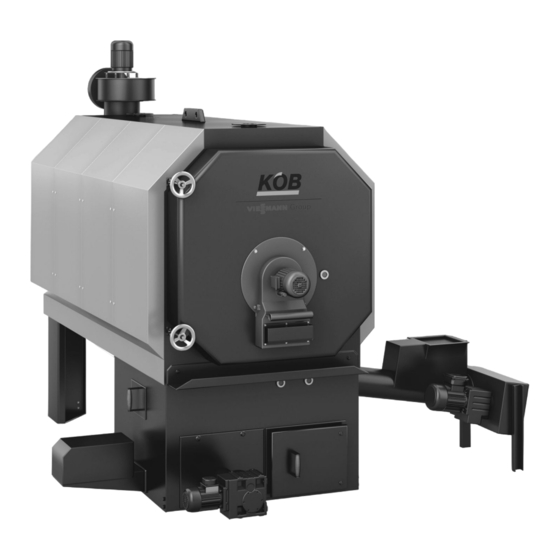
PYROT rotation combustion 2.1 Product description A Controlled secondary air with rotary fan B Rotary combustion chamber C Boiler heat exchanger D Safety heat exchanger E Flue gas fan with Lambda probe and temperature sensor F Pneumatic cleaning G Flue gas recirculation, controllable H Regulated primary air K Ignition fan L Fully moving grate... -
Page 9: Specification
PYROT rotation combustion (cont.) 2.2 Specification Specification Trade name Pyrot rotation combustion Rated output Part no.: 7423 656 7423 657 7423 658 7423 659 7423 660 7423 661 Output data Rated output Continuous output Minimum output Q Heating data – Content on hot gas side 1340 1613 –... - Page 10 PYROT rotation combustion (cont.) Trade name Pyrot rotation combustion Rated output Part no.: 7423 656 7423 657 7423 658 7423 659 7423 660 7423 661 Flue gas Average temperature (gross – Average flue gas temperature with Q °C – Average flue gas temperature with Q °C Mass flow rate –...
- Page 11 PYROT rotation combustion (cont.) Dimensions 8.22 mm 38.51 mm 23.53 mm 9.04 mm 2.67 mm 77.57 mm 23.03 mm 19.57 mm KR Boiler return KV Boiler flow Dimensions Rated output 1291 1541 1525 1875 1800 2030 1891 1908 2168 2182 2457 2527 1093...
- Page 12 PYROT rotation combustion (cont.) 5,30 mm 54,17 mm 6,68 mm 70,02 mm A Sensor well for TS F Boiler water temperature sensor B Boiler return G Boiler flow C Return temperature sensor H Safety heat exchanger D Safety heat exchanger K Ash removal, combustion block E High limit safety cut-out (STB) Dimensions...
- Page 13 PYROT rotation combustion (cont.) A Flue gas fan F Ash doors of the grate ash container (2 pce) B Boiler door with rotary fan G Drive, ash removal C Extinguishing water connection H Maintenance cover, combustion block D Supply screw conveyor K Ash removal, rising screw conveyor E Drive, infeed grate PYROT...
-
Page 14: Control Unit 3. 1 Specification For Ecotronic
Control unit 3.1 Specification for ECOTRONIC The Ecotronic system control unit is a decentralised microprocessor system (CAN BUS). To control the boiler system, the Ecotronic com- prises a module (PCB) integrated into the control panel, and the pro- gramming module. Controller modules can be added to the Ecotronic (modular structure). -
Page 15: Accessories For Ecotronic
Control unit (cont.) 3.2 Accessories for Ecotronic Modules and data cables The standard Ecotronic version can be customised with additional Controller module controller modules or controllers and data cables. Additional heat The controller module is supplied in a plastic casing (length 325 mm, sources, heat consumers or DHW cylinders can be incorporated into height 195 mm, depth 75 mm) incl. -
Page 16: Controller, Central Heating
Control unit (cont.) Controller, central heating Part no. 7379 402 Weather-compensated heating control unit with digital time switch for setback mode according to individual day and seven-day program, with pump control unit, frost protection function, eco mode and limited flow temperature. Standard delivery: ■... -
Page 17: Safety Thermostat Rak-Tw.1000B
Control unit (cont.) Safety thermostat RAK-TW.1000B Part no. 7387 940 For safe limitation of the flow temperature of a heating circuit. Standard delivery: ■ Safety thermostat RAK-TW.1000B A Safety thermostat RAK-TW.1000B Controller, long-distance line Part no. 7379 401 Via a long-distance line, a building is supplied with separate heat dis- tribution. -
Page 18: Controller, Space Heater
Control unit (cont.) Controller, space heater Part no. 7387 825 The space heaters are supplied with maximum flow temperature by the boiler cylinder system. The switching of the fan is carried out by on-site switches or controllers. The flow rate of the heating water is controlled via the return temper- ature and matched to the output of the space heater (flow control). -
Page 19: Controller, Dhw Cylinder B2
Control unit (cont.) Controller, DHW cylinder B2 Part no. 7379 400 When its temperature drops, the DHW is reheated via the integral heat exchanger directly by the boiler or by the buffer cylinder. This is dependent on a corresponding difference in temperature (either dif- ferential temperature or fixed temperature control unit). -
Page 20: Controller, Solar Dhw Cylinder
Control unit (cont.) Controller, solar DHW cylinder Part no. 7387 818 Use for single solar thermal system as a single circuit control unit for heating the DHW in the solar DHW cylinder. If the temperature of the DHW (in the lower section of the DHW cylin- der) falls below the collector temperature, the DHW is heated by the solar collector (adjustable differential temperature: 2 - 20 °C). - Page 21 Control unit (cont.) Flow Return --M6X.1-- --Y20-- --M20-- 2 2 4 --B28.1-- --B28.2-- --B6X.1-- --B28.3-- --B6X.2-- --Y6X.1-- --M6X.2-- KW Cold water Plate heat exchanger WW DHW Secondary pump Solar collector Charging valve, buffer cylinder front/back Solar station with solar circuit pump Boiler Thermostatic water mixer PYROT...
-
Page 22: Accessories For Ecotronic Output Management
Control unit (cont.) 3.3 Accessories for ECOTRONIC output management Cylinder management 3 sensors Part no. 7387 828 Standard delivery: Modulating output operation of the PYROT rotation combustion sys- ■ 2 additional sensors KTY with sensor well 1/2" x 280 mm tem is optimised with the use of a buffer cylinder. -
Page 23: Accessories For Ecotronic Remote Transfer
Control unit (cont.) 3.4 Accessories for ECOTRONIC remote transfer Fault message device, analogue with battery Part no. 7387 994 To be carried out on customer side: Four different text messages are possible, as the fault message ■ Electrical connection of the phone line to the modem modem has four independent digital inputs. -
Page 24: Visualisation, Externally Via Modem (Connected With Cable)
Control unit (cont.) Visualisation, externally via modem (connected with cable) Part no. 7387 792 Images on the screen: Package for the transmission of relevant data to an EDP workstation ■ Cross-section image of boiler, 3D with display fields (internal and/or external) for the visualisation, remote maintenance ■... -
Page 25: Mastercontrol For Two-Boiler Systems
Control unit (cont.) 3.5 Mastercontrol for two-boiler systems The Mastercontrol optimises the entire heat generation of two biomass boilers (PYROT dual system) incl. control of an oil, gas or electric boiler as a redundancy and/or as a peak load boiler. Information on the Mastercontrol Function: Operation:... -
Page 26: Schematic Diagram
Control unit (cont.) Schematic diagram ECOTRONIC ECOTRONIC MASTER- B28.1 CONTROL PYROT 1 PYROT 2 B28.2 B28.3 B28.4 B28.5 ECOTRONIC ECOTRONIC MASTER- CONTROL Schematic diagram of a two-boiler system with Mastercontrol A Additional heat source E Exclusively charging boiler 1 in control unit boiler 1 B Flow consumers F Exclusively charging boiler 2 in control unit boiler 2 C Buffer cylinder as low loss header... -
Page 27: Accessories For Mastercontrol
Control unit (cont.) 3.6 Accessories for Mastercontrol Heat meter signal Part no. 7387 975 Note Only for Mastercontrol. With this analogue input (0-10 V signal), the external heat meter can be read into the Mastercontrol. The current values can be displayed on the screen. -
Page 28: Fault Message Device, Analogue With Battery
Control unit (cont.) Fault message device, analogue with battery Part no. 7387 840 To be carried out on customer side: Transmits the boiler system fault messages as a phone message. The ■ Electrical connection of the phone line to the modem fault message must be acknowledged. -
Page 29: Heating Water Buffer Cylinder 4. 1 Specification, Buffer Cylinder
Heating water buffer cylinder 4.1 Specification, buffer cylinder Buffer cylinder HPM Buffer cylinder for integration in a wood combustion system with a Flexible foam insulation to HPM maximum boiler output of up to 150 kW. The insulation is made from 100 mm thick flexible PUR foam elements with polystyrene casing. -
Page 30: Buffer Cylinder Wdw 2000 L
Heating water buffer cylinder (cont.) Part no. buffer cylinder HPM 7424130 7424131 7424132 7424133 7424134 7424135 Part no. flexible foam insulation to 7424136 7424137 7424138 7424139 7424140 7424141 buffer cylinder HPM Female connection, 1¼ 1¼ 1¼ 1¼ 1¼ 1¼ Sensor pipe Ø14xL1400 Ø14xL1400 Ø14xL1400... -
Page 31: Buffer Cylinder Wdw 2900 L
Heating water buffer cylinder (cont.) Buffer cylinder WDW 2900 l Part no. 7439 106 Rigid foam insulation to WDW 2900 l Buffer cylinder for integration in a wood combustion system with a maximum boiler output of up to 540 kW. Part no. -
Page 32: Installation Accessories 5. 1 Boiler Safety Equipment
Installation accessories 5.1 Boiler safety equipment Thermally activated safety valve 100 °C Part no. 7387 405 Standard delivery: Standard version for response temperature approx. 100 °C, connec- ■ Thermally activated safety valve incl. sensor well tion R . ¾ Note We recommend the thermally activated safety valve even if there is no need to use it in accordance with the local safety regulations. -
Page 33: Accessories, Heat Distribution
Installation accessories (cont.) 5.2 Accessories, heat distribution Motor three-way valve for Pyrot 100 kW Designation Rated output Part no. Motor three-way valve, VXG 48.40/SQS 35.0 (ZV-3-40) 100 kW 7388 204 Precise control characteristics and an airtight seal without leaks. Type Servomotor Incl. -
Page 34: Accessories, Flue System
Installation accessories (cont.) 5.3 Accessories, flue system Flue gas dust extractor The flue gas dust extractor minimises dust emissions and is designed Note as a multi cyclone with axial function. The dust extractor is fully insu- The flue gas dust extractor is required for fuels with an increased per- lated and has three covers for cleaning. - Page 35 Installation accessories (cont.) 31,22 mm 4,07 mm 8,86 mm 14,12 mm 8,26 mm < 200 10,57 mm 6,02 mm 28,23 mm 90 l 28,23 mm Positioning in 4x 90° possible (removal, ash container) A Flue gas fan (with variable rotation) C Dust extractor (axial cyclone) ■...
-
Page 36: Metal Mesh Filter
Installation accessories (cont.) Metal mesh filter The metal mesh filter removes dust and fine dust from the flue gas. It Filter operation is controlled via the boiler control unit. Operation is is characterised by a particularly high degree of separation. This carried out via the control unit programming module. -
Page 37: Cleaning, Pneumatic
Installation accessories (cont.) Dimensions Rated output Dimensions 1413 1413 1413 1833 1833 1833 2097 2097 2097 1720 1720 1720 2230 2230 2230 2820 2820 2827 1270 1270 1400 1670 1670 1717 1730 1730 1770 2255 2255 2400 1192 1192 1040 1069 1069 1069... -
Page 38: Price Reduction Net Compressed Air On Site
Installation accessories (cont.) ■ Valves fully wired on terminal strip To be carried out on customer side: ■ Software module in the control unit ■ Provision of a socket 400 V / 16 A ■ Connector for compressor 400 V / 16 A Specification Rated output Part no.:... -
Page 39: Accessories, Ash Removal
Installation accessories (cont.) 5.4 Accessories, ash removal External container Complete screw conveyor ash removal from the ash chamber of the ■ Connection station with mobile ash container combustion block into an external, mobile and zinc-plated ash con- ■ Control of the screw conveyor drives tainer (standard 240 litres). - Page 40 Installation accessories (cont.) 14,61 mm 3,21 mm 10,42 mm 4,72 mm Ash removal in external container 240 l Dimensions Rated output Volume of ash container Part no.: 7387 918 7387 918 7387 918 7387 918 7387 918 7387 918 1023 1023 1193 1273...
-
Page 41: Ash Removal Into The Base Container
Installation accessories (cont.) Ash removal into the base container Complete screw conveyor ash removal from the combustion block ash Standard delivery: chamber into the base container located under the boiler with maxi- ■ Boiler ash trough with ash level control and ash removal screw con- mum capacity. -
Page 42: Safety Temperatures
Design information (cont.) Safety temperatures The boilers comply with EN 303 and DIN 4702, and are all CE-desig- ■ Permissible flow temperatures (= safety temperatures): nated and can be used in sealed heating systems as per EN 12828. up to 110 ºC To EN 12953: up to 120 ºC ■... -
Page 43: Requirements Of The Muster-Feuerungsverordnung [Germany]
Design information (cont.) ■ Avoid air contamination through halogenated hydrocarbons (e.g. as If these instructions are not observed, any consequential losses in sprays, paints, solvents and cleaning agents) directly related to any of these causes are excluded from our war- ■... -
Page 44: Safety Precautions
Design information (cont.) cm² A = 150 cm² + 2 x (Σ n – 35 kW) ² Σ² = total of all rated outputs in kW Never close or obstruct combustion air apertures and lines. Use spe- cial safety equipment to ensure that the combustion equipment can only be operated when the aperture is open. -
Page 45: Water Connection
Design information (cont.) 6.5 Water connection Heating connections Existing systems Connect all heat consumers and heating circuits to the boiler flow and Before connecting to an existing heating system, thoroughly flush the return connectors. Never make any connections to the safety flow or wood boiler to remove dirt and sludge. - Page 46 Design information (cont.) Sizing recommendation for systems with sealed expansion, buffer cylinder circuit if required B28.1 B28.2 B28.3 TS131 B28.1 PYROT B28.3 B28.2 B28.1 Example 1 A Additional heat source G Low loss header (version C) B Buffer cylinder as low loss header (version A) (possible with large water volume in mains) (3 sensors, optionally 5 sensors) H With additional heat source, dual mode - oil, gas, electric...
-
Page 47: Electrical Installation
Design information (cont.) K Additional heat source controlled with a directional control valve for oil/gas boiler L Additional heat source controlled with a directional control valve - Oil/gas boiler - Electric heater Sizing recommendation Trade name Pyrot rotation combustion Rated output Boiler circuit NW 40 NW 50... -
Page 48: Extinguishing Water Container
Design information (cont.) Extinguishing water container Part no. 7387 785 C Material supply D Combustion Note The extinguishing water container is part of the boiler. Note ■ Adjustment, valve, Danfoss AVTA 15 50–90 °C 3 corresponds to 80 °C. ■ Lines should be secured in metal pipes (½“). ■... -
Page 49: Prevention Of Combustion Chamber Overfilling
Design information (cont.) Prevention of combustion chamber overfilling In accordance with TRVB 118, a fill level monitor should be installed As a result, any prescribed protection device does not come into effect to prevent overfilling of the combustion chamber. The boiler has two and normal operation is maintained with regard to the greatest possible light barriers for incandescence monitoring. -
Page 50: Fire Protection
Design information (cont.) Replacement, expansion vessel An additional expansion vessel and discharge pipe are not required if a second high limit safety cut-out and a second maximum pressure limiter are installed. 6.8 Fire protection The fire safety regulations for wood combustion systems vary depend- The regulations valid for the relevant installation location must be ing on the country. -
Page 51: Fuel Discharge By Means Of Screw Conveyor
Design information (cont.) 6.11 Fuel discharge by means of screw conveyor Discharge screw conveyor, pellet, D = 120 mm As pellet transportation from a rectangular room with the possibility of Note filling from the top. The pellets trickle via a tilted intermediate floor into Price given per m;... -
Page 52: Drive, Discharge Screw Conveyor, Pellets
Design information (cont.) 5,92 mm 77,60 mm 24,36 mm <200 7,53 mm 5,15 mm 180x180 102,15 mm 14,79 mm 14,03 mm 4,96 mm ~ 500 166 1,48 mm C - C 9,79 mm 6,21 mm 10,20 mm 24,31 mm 40,28 mm A Possible outlet into a bunker C Intermediate floor B Optional drive, left or right... -
Page 53: Fuel Discharge By Means Of Agitators
Design information (cont.) ■ Control of spur geared motor 3 x 400 V according to boiler control unit ■ Inspection cover with safety limit switch and sealed outlet 6.12 Fuel discharge by means of agitators Spring core discharge AF Part no. 7387 846 for spring core discharge 3.5 m Part no. - Page 54 Design information (cont.) Sizing ø a 4,14 mm 52,24 mm ø 150 72,64 mm 11,89 mm < 6000 24,75 mm 8,80 mm 13,20 mm 22,00 mm A Second leaf spring D Shavings B Installation opening E Remnants (seal with fire-retardant panel) F Pellets C Rotational direction G Base (height adjustable)
-
Page 55: Discharge Screw Conveyor Af To Spring Core Discharge
Design information (cont.) Note 1. Installation position, horizontal: preferably in concrete with recess for screw conveyor and central gear. 2. Installation position, angled: exclusively with intermediate floor, preferably made from wood. 3. Suitable for woodchips up to G30/50; not suitable for wood bri- quettes and shredded matter from used or waste wood. - Page 56 Design information (cont.) 42,99 mm 4,33 mm 18,03 mm ø 1490 34,54 mm37,56 mm 14,59 mm < 200 7,29 mm > 10000 A Axis, agitator C Rotational direction B Screw conveyor axis D Centre, agitator Sizing the horizontal discharge AH with agitator and discharge screw conveyor Min.
- Page 57 Design information (cont.) 76,25 mm > 10000 3,65 mm < 200 < 170 < 600 1,52 mm 33,67 mm L1 + 200 1260 PYROT...
-
Page 58: Discharge Screw Conveyor Ah For Horizontal Discharge
Design information (cont.) Installation position, horizontal (version 1) D Axis, screw conveyor Installation position, sloping (version 2) E Axis, agitator Finished floor, concrete-lined (concrete block out for recessed F Sub-structure installation) G Building floor A Finished floor H Centre, agitator B Seal installation opening with fire-retardant panel K Concrete block out (for recessed installation) C Base (height adjustable) -
Page 59: Fuel Discharge By Means Of Funnel Discharge
Design information (cont.) 6.13 Fuel discharge by means of funnel discharge Funnel discharge Material discharge for round silos is carried out with an agitator inte- Standard delivery: grated in the discharge casing. In its centre, the discharge screw con- ■ Funnel discharge as per order data with drive unit 3 x 400 V veyor is driven via a solid universal joint. -
Page 60: Additional Outlet Flange
Design information (cont.) Version and drives Funnel discharge AP-11 AP-12 AP-Z02 Part no. 7837 794 7837 958 7388 042 2205 3005 3005 1030 1030 Additional outlet flange Part no. 7387 520 Additional connection option for conveyor devices to discharge casing for twin-boiler system. -
Page 61: Specification For The Pushrod Drives
Design information (cont.) Max. permissible dumping height and length of the pushrods in S650 Trade name Pushrod Type AS-2.50 AS-2.25 AS-2.0 AS-1.75 AS-1.5 Part no.: 7387 992 7387 995 7387 836 7387 956 7387 989 Dumping height with length: Specification for the pushrod drives Trade name Pushrod drive Type... -
Page 62: Slot Discharge, For Pulling
Design information (cont.) FZD Maximum pressure force on the weld base for pushrod drive FZZ Maximum tensile force on the weld base for pushrod drive Number of pushrods 1x FS1 1x FS1 2x FS1 1x FR1 1x FR1 Standard version 160 kN 130 kN 362 kN... -
Page 63: Centre Discharge
Design information (cont.) 10,29 mm 6,02 mm 0,89 mm 19,48 mm 9,50 mm 1230 27,72 mm > 1750 95,02 mm (4000 - 12000) 0,48 mm 50 - 150 A - A Required order data for the above example: Position Part no. Quantity Unit Designation... - Page 64 Design information (cont.) Specification Centre discharge Screw conveyor Screw conveyor D = 190 mm D = 250 mm For max. dumping height, see page 60 For max. dumping height, see page 60 In the middle third of the silo length In the middle third of the silo length >...
-
Page 65: Slot Discharge With Fill Function
Design information (cont.) Required order data for the above example: Position Quantity Unit Designation Pushrod drive AS individual with hydraulic cylinder type K Weld base, bunker Cover, centre discharge Push floor screw conveyor Pushrod (incl. stop wedges) Version and drive, AQ standard Hydraulic compartment Hydraulic drive, ASH individual Weld base, AS individual... - Page 66 Design information (cont.) 9,71 mm 5,86 mm 3,57 mm 16,78 mm 9,32 mm 1080 > 3000 46,60 mm 15,53 mm 0,50 mm A - A 50 - 150 46,60 mm 46,60 mm < 8000 < 12000 93,20 mm (< 20000) 3,03 mm 0,54 mm 50 - 150...
-
Page 67: Fuel Discharge By Means Of Push Floor (Accessory)
Design information (cont.) Required order data for the above example: Position Quantity Unit Designation Pushrod drive AS twin with hydraulic cylinder type K Cover for push floor screw conveyor (optional) Weld base, bunker Pushrod (incl. stop wedges) Push floor screw conveyor Version and drive, AQ standard Hydraulic drive, ASH twin Weld base, AS twin... -
Page 68: Pushrod
Design information (cont.) To be carried out on customer side: Note ■ Manufacturing the concrete floor Article price per m. ■ Installation of the profiles level with the concrete floor (max. deviation Total price is calculated as follows: of 5 mm to 10 m) for pushrod drive, individual: (pushrod drives in pce x length of bunker in m) + (1 x width of bunker in m) x article price. -
Page 69: Hydraulic Drive, As Twin
Design information (cont.) Hydraulic drive, AS twin Hydraulic drive to actuate twin pushrod drives with discharge and fill ■ Control of discharge function: function. When the required fill level of the push floor screw conveyor According to the boiler control unit, fuse protected with temperature is reached, the discharge function is switched off. -
Page 70: Drive, Push Floor Screw Conveyor, Standard
Design information (cont.) Drive, push floor screw conveyor, standard Part no. 7387 904 Standard delivery: Standard version for push floor screw conveyor with pulling drive and ■ Drive unit with spur geared motor 400 V and chain drive discharge into a drop section. The system is driven via spur geared ■... -
Page 71: Drive, Trough Screw Conveyor, Standard
Design information (cont.) A - A 7,54 mm 1,11 mm 6,40 mm > 30 5,51 mm 5,80 mm 6,38 mm 13,77 mm 4,82 mm 14,51 mm ~ 500 A Drive (optionally on the l.h. or r.h. side) B Inspection clearance Trade name Trough screw conveyor Type... - Page 72 Design information (cont.) The pipe screw conveyor is ideal for conveying pourable wood fuels Note and/or in the case of steep ascending inclines. Article price per m. Total price: length L in m x article price. Standard delivery: ■ Pipe screw conveyor according to the project drawing Trade name Pipe screw conveyor Part no.:...
-
Page 73: Drive, Pipe Screw Conveyor, Pellet
Design information (cont.) 13,90 mm 3,36 mm 10,55 mm 5,99 mm 2,56 mm 5,25 mm 4,60 mm A Drive (optionally on the l.h. or r.h. side) D Pipe screw conveyor, vertical, pushing B Distributing container E Pipe screw conveyor, horizontal, pushing C Distributing screw conveyor Drive, pipe screw conveyor, pellet Part no. -
Page 74: Drive, Pipe Screw Conveyor, Standard
Design information (cont.) Drive, pipe screw conveyor, standard Part no. 7387 814 Standard delivery: Standard version for pipe screw conveyor with pulling drive and dis- ■ Drive unit with spur geared motor 3 x 400 V and chain drive charge into a drop section. The system is driven via spur geared motor ■... -
Page 75: Pellet Storage Room Design And Required System Components
Design information (cont.) ≥ 500 mm 40° A Fill connector E Empty space B Return connector F Discharge system G Available volume = ⅔ of the room C Air space D Sloping floor Pellet storage room design and required system components ≥... -
Page 76: Additional Safety Instructions For Pellet Stores
Design information (cont.) ■ The pellet storage room must be dry, as pellets will swell up markedly ■ Avoid the installation of water pipes inside the storage room because if exposed to moisture. This leads to substantial difficulties in deliv- of condensation and the risk of burst pipes. - Page 77 Design information (cont.) Connector length and location If connectors must be located on the long side of the storage room, we The length of the fill connector is subject to the distance from the return recommend alternating the filling between the connectors. This connector.
- Page 78 Design information (cont.) Connector installation options Setting into brickwork The connector is bricked into the outlet without thermal insulation. A Fill connector B Wall outlet Ø 150 mm Wall installation with screws C Pipe clip for earthing The connector is secured to the outside wall with screws and is earthed D Wall outlet Ø...
-
Page 79: Fuel Storage In On-Site Pellet Store (Accessories)
Design information (cont.) Installation into a lighting duct C Extension pipe Connectors may be installed through a wall or through a window open- D Wall outlet Ø 110 mm ing. The shortened fill and return connectors are inserted in a 45º bend. The bend is inserted into an extension pipe routed through the wall or Outlet Ø... -
Page 80: Extension Of Fill Connector And Return Connector
Design information (cont.) Extension of fill connector and return connector Part no. 7388 056 Standard delivery: ■ Extension DN 100, length 700 mm, zinc-plated ■ Union nut for fitting ■ Clip for fastening 6.19 Fuel storage in on-site bunker (accessories) Silo cover, manual FDM 2.9/1.3 m Part no. -
Page 81: Bunker Cover Hydraulic Fdh
Design information (cont.) A All-round seal (not included in standard delivery) B Rod clearance, fall protection grille C 10x secured with screws Bunker cover hydraulic FDH Cover for secure sealing of openings for wood fuel delivery. The cover ■ Hydraulic cylinder with hinge lug connection, pipe break protection, is controlled manually using a hydraulic cylinder. - Page 82 Design information (cont.) 62,77 mm A Fall protection grille (optional) B Rubber apron C All-round seal, required, not included in standard delivery Recommendation: Kemperol combi roof seals Specification FDH 4.0/2.4 FDH 5.5/2.4 FDH 7.0/2.4 FDH 8.5/2.4 Type 7388 011 7387 903 7387 834 7387 884 Part no.
-
Page 83: Fall Protection Grille 120 For Fdh
Design information (cont.) Fall protection grille 120 for FDH Fall protection grille for corresponding bunker cover in several ele- Standard delivery: ments to prevent anyone falling in when the cover is open. Each ele- ■ Support profile for installation in ceiling recess ment is prepared for installation of a shaker motor (shaker motor for ■... - Page 84 Design information (cont.) 1,90 mm ø102 37,68 mm 56,10 mm 1,87 mm 58,53 mm 1,87 mm ±0,0 A Filling on customer side (concrete or asphalt) E Filling level B Channel for rainwater F Fall protection grille (optional) C Rainwater drain (on site) G All-round seal (required) (on site) D Threaded fitting H Drain channel, running water (on site)
-
Page 85: Fall Protection Grille, 120 For Fdb
Design information (cont.) Specification Bunker cover, movable FDB FDB 3.0/2.0 m FDH 3.8/2.4 m FDH 3.2/3.2 m Part no. 7387 850 7387 793 7387 974 3000 3800 3200 2110 2510 3310 2000 2400 3200 3150 3950 3350 2530 2930 3730 2150 2550 3310... -
Page 86: Cover Drives For Hydraulic Drive, Ash
Design information (cont.) – Hydraulic hoses – Wall mounting brackets ■ Control: – According to the boiler control unit, fuse protected with tempera- ture and level switch in the oil container ■ Key switch button OPEN/OFF/CLOSED for installation of a locking cylinder on the customer side (installation close to cover) Note Application in the case of silo discharge systems without hydraulic... -
Page 87: Back Burning Protection
Design information (cont.) 10,19 mm 1,54 mm 1300 13,51 mm < 1500 6.20 Back burning protection Rotary lock valve Rotary lock valve for fire protected separation of combustion system Note and fuel store with overpressure or underpressure, and with simulta- Rotary lock valve 190 for supply system D 120 mm. -
Page 88: Shut-Off Gate Valve Ma 220
Design information (cont.) Trade name Rotary lock valve Type MZ 190 MZ 260 Part no.: 7388 022 7387 888 7193 7264 d (Di) e (Da) e (Di) e (Da) Output, drive 0.75 0.75 Drive speed Shut-off gate valve MA 220 Part no. -
Page 89: Connection On The Flue Gas Side
Design information (cont.) 6.21 Connection on the flue gas side Chimney The system is equipped with a flue gas fan and therefore the combus- A chimney compliant with regulations relevant to the rated boiler output tion equipment does not require a draught. The stack sizing should be is required for efficient boiler operation. -
Page 90: Sound Insulation
Design information (cont.) Flue pipe, L = 1000 mm Flue pipe, L = 1000 mm Part no. Version: black, without insulation D = 200 mm 7388 233 D = 250 mm 7388 194 D = 300 mm 7388 148 D = 350 mm 7387 425 6.22 Sound insulation Braces... -
Page 91: Selection Example
Appendix (cont.) Selection example Datum: From the table: = 3 bar (response pressure of the safety valve) With p = 3 bar, p = 1.5 bar, V = 1153 l = 13 m (static ceiling of the system) = 250 l (for V max. -
Page 92: Electrical Installation
Appendix (cont.) 7.4 Electrical installation Carry out the electrical connection and installation in accordance with ■ DIN VDE 0100: Installation of HV systems with rated voltages up to VDE regulations (DIN VDE 0100 and DIN VDE 0116), local regulations 1000 V and the technical connection requirements laid down by your electricity ■... -
Page 93: Keyword Index
Keyword index Accessories Low water indicator................49 ■ For control unit............22, 23, 25, 27 ■ For the boiler.................32 ■ For the control unit................15 Mastercontrol................25, 27 Agitators Maximum pressure limiter..............49 ■ Discharge system.................53 Minimum pressure limiter..............49 Minimum wood fuel requirements............7 Boiler circuit pump................45 Boiler room..................42 Output management................22 Building Regulation approval process..........92... - Page 94 PYROT...
- Page 95 PYROT...
- Page 96 Subject to technical modifications. Viessmann Werke GmbH&Co KG Köb Holzheizsysteme GmbH D-35107 Allendorf Flotzbachstrasse 33 Telephone: +49 6452 70-0 A-6922 Wolfurt Fax: +49 6452 70-2780 Telefon: +43 (0)5574 6770-0 www.viessmann.com Telefax: +43 (0)5574 65707 www.koeb-holzfeuerungen.com PYROT...
Need help?
Do you have a question about the KOB PYROT and is the answer not in the manual?
Questions and answers