Table of Contents
Advertisement
Quick Links
Advertisement
Table of Contents

Related Manuals for KOB KOB PYROT SERIES


Summary of Contents for KOB KOB PYROT SERIES
- Page 1 Operation and Maintenance Instructions PYROT 100 to 540 ID: 106811-H English...
- Page 2 © by KÖB Holzfeuerungen GmbH Flotzbachstraße 33 A-6922 Wolfurt All rights reserved, including photomechanical reproduction and storage in electronic media. Viessmann Group...
-
Page 3: Table Of Contents
General Information_________________________________________________ 4 Foreword _______________________________________________________________________ 4 Technical standing _______________________________________________________________ 4 Intended use ____________________________________________________________________ 4 Technical data ___________________________________________________________________ 4 Information documented __________________________________________________________ 4 CE-certification __________________________________________________________________ 4 Important Information _______________________________________________ 5 Safety instructions _______________________________________________________________ 5 Excess temperature/power failure __________________________________________________ 5 Low water/excess water pressure___________________________________________________ 5 A fire hazard ____________________________________________________________________ 6 Wood fuels, minimum requirements _________________________________________________ 6 Filling the fuel storage unit ________________________________________________________ 6... -
Page 4: General Information
Any other use of the PYROT or use of it going be- 1 General Information yond this will be considered as unintended use unless written approval by the manufacturer has 1.1 Foreword been obtained. Dear System Owner, you have made a good se- Operation of the PYROT by unqualified per- lection in the PYROT. -
Page 5: Important Information
2.2 Excess temperature/power failure 2 Important Information 2.1 Safety instructions CAUTION DANGER OF THIS SUDDENLY GOING UP IN When carrying out work on the heating sys- FLAMES: tem, such as cleaning and maintenance, wear Do not open the doors or lids on the boiler appropriate protective equipping when re- plant! quired. -
Page 6: A Fire Hazard
2.4 A fire hazard Heating out of operation: With insertion-type firing systems, the conveying If the articulated arms or spring-mounted route creates a connection between the silo and plates are still covered by fuel, refilling can be the burning material in the boiler plant. carried out immediately. -
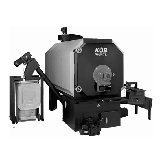
Page 7: How The Boiler Plant Is Strucured
3 How the Boiler Plant is Strucured (Illustration: PYROT 300) (1) Feed auger with isolating layer (8) Rotation combustion chamber (KÖB- (2) Drive for moving grate patented) (3) Automatic ignition device (9) Boiler heat exchanger (4) Controlled combustion air supply system (10) Boiler door (5) Moving grate (11) Heat exchanger for thermal run-off safety... -
Page 8: Commissioning/Operation
4 Commissioning/Operation 4.1 The initial start-up When the "System Temperature Setting" is The initial start-up is carried out either by KÖB fallen short of, the facility is automatically star- Holzfeuerungen GmbH or a competent individual ted back up. named by it. 4.2.3 Switching off Be absolutely sure to follow the instructions in Press the F1 key "PYROT Wood". -
Page 9: Oil Burners On A Pyrot
5 Oil burners on a Pyrot Be sure to note: The oil burner's firing power may amount to a maximum of 70% of the rated heat output in wood-burning operation. The selection of the oil burner as well as the actual nozzle length have to be determined by the supplier of the oil burner. -
Page 10: The Ecotronic Control System
F3 (PYROT Parameters) 6 The ECOTRONIC control system Setting parameters, set point values, the date and time F4 (PYROT Loader System) Setting of cycle switchover switching, advance- flow and post-flow times F5 (Group 1) Setting parameters and set point values (heat distribution, Group 1) F6 (Group 2) Setting parameters and set point values... -
Page 11: Boiler And Loader System (F3/F4)
6.3 Boiler and loader system (F3/F4) (16) Storage Unit Management, Temperature, Storage Unit Average (80°C): Set point value, average temperature, storage unit 6.3.1 The F3 KEY: "PYROT Parameters" boiler output is reduced according to loading of storage unit. (mask number) parameter (factory setting) (Indication only for storage unit option) (01) Storage unit temperatures ( - ): (17) Start boiler when the system temperature... -
Page 12: The F4 Key: "Pyrot Loader System
6.3.2 The F4 KEY: "PYROT Loader System" (mask number) parameter (factory setting) (01) Cleaning (NO): This activates the cleaning function. Exhaust fan at starting speed, and moving grate on. (05) Moving grate, pause (60 s): Cycle switching for the moving grate (adjustable pause time, impulse fixed, 2 seconds). -
Page 13: Extended Control Systems F5 - F8 (Optional)
6.4 Extended control systems F5 – F8 (op- tional) (04) Heating Period 1/Start (6:00) Time to switch from lowered temperature (or off) The F5 to F8 keys are assigned customer-specific to normal temperature. extended control systems as desired. Each ex- tended control system is assigned a separate key. - Page 14 The heating curve Room thermostat (ECO-ZR-QA): The correspondence of the flow temperature to The Model QAA 35 Room Thermostat can be the outdoor temperature can be set directly and used with or without influence by the room tem- read directly. The setting is carried out by two perature.
-
Page 15: Utility Water Heater
6.4.2 Utility water heater (mask number) parameter (factory setting) Function: ECO-B1 (01) Operating mode (timer) When the temperature of the utility water Select operating mode drops, it is reheated by the built-in heat ex- changer from the heat accumulator (hydraulic (02) Number of heating periods (1) switcher). -
Page 16: Air Heater
6.4.3 Air heater Function (ECO-L): (05) Heating Period 1/End (22:00) Time to switch off air heater. The air heaters are supplied at maximum flow temperature from the boiler plant storage system. (06-23) Heating Periods 2-7 The fans are connected by switches or controllers These depend on the number of heating periods provided by the customer. -
Page 17: Annex Buildings
6.4.4 Annex buildings Function (ECO-N): (04) Heating Period 1/Start (6:00) Time to switch from lowered temperature (or off) The pipeline is usually supplied with a lowered to normal temperature. temperature required by the weather-guided heat- ing control system. The utility water heater is (05) Heating Period 1/End (22:00) loaded at the maximum flow temperature set. -
Page 18: Pipelining
6.4.5 Pipelining The heating curve Function (ECO-F): See "Extended control system for room heating unit" This is for an annex building with a separate heat Room thermostat (ECO-ZR-QA): distribution system, which is supplied with heat via a pipeline. According to prompts by the heat dis- See "Extended control system for room heating tribution system, the temperature of the pipeline is unit"... -
Page 19: Additional Heat Generator
6.4.6 Additional heat generator Function (ECO-KP1): (10) Load storage unit to (70°C): To what temperature on the accumulator sensor The additional heat generator is automatically selected should the additional heat generator heat connected when required. This takes place after up the accumulator? the system temperature is fallen short of that is (Indication only with accumulator option) set for covering the entire heat requirement or a... -
Page 20: Solar
6.4.7 Solar Function (ECO-S1): Operating modes This is used in simple solar systems with a single Off: control circuit to heat the utility water in the solar Pump off; valve shut utility water heater (Art. No: WSS-___). Automatic: ECO-S1 controller is an additional component for Automatic heating of the solar utility water the ECO-B1(2) controller for the utility water heater and of the accumulator by means of dif-... -
Page 21: Cleaning/Maintenance
7 Cleaning/Maintenance 7.1 Boiler Regular cleaning and maintenance of the facility is the customer's most important job for years of trouble-free operation and to obtain the greatest possible output with the best efficiency. Here the cleaning intervals for chip material are listed as per ÖNORM M 7133 with clinging bark – 0.8% ash content. - Page 22 Exhaust gas deduster, detached (optional) Pneumatic tube-cleaning system (optional) After approx. 1000 operating hours: Unplug the plug, unscrew butterfly nuts, pull out motor with impeller and clean with broom or wire brush. CAUTION: DANGER OF INJURY – be abso- lutely sure to switch off master switch. After each cleaning of the set of tub- Open lid and clean the guide blades of the de-duster with hand-brush.
-
Page 23: Installing The Displacement Rods Into The Heat Exchanger
7.1 Installing the displacement rods into the heat exchanger The displacement rods improve the heat transmis- sion in the heat exchanger and reduce the tem- perature of the exhaust gas, thus improving the ef- ficiency of the heating system. They are taken out to clean the heat exchanger tubes and then put back in. -
Page 24: Feed Systems
7.2 Feed systems Why? The "intermittent control system" switches the All the geared motors on the feed systems are consumer pumps on for five seconds every 24 maintenance-free. hours. This prevents the pumps from jamming during long standstills. This saves on expensive A change of lubricant and/or oil is recom- repairs. - Page 25 Spec Sheet 1010/d-1 Wood Fuels Minimum Requirements / Information 2007-09-12_E A prerequisite for approval is the express permission for such by the public authority responsible. For claims to the warranty according to Section 11 of our General Terms and Conditions of Delivery, wood fuels have to meet the following conditions.
- Page 26 Spec Sheet 1010/d-2 Wood Fuels Minimum Requirements / Information 2007-09-12_E 4.2) Chips not from the forest; origin as per 3.2, 3.3, 3.4; briquettes, origin as per 3.3 Size essentially as per ÖNORM M 7133 G50, additionally, however: - Fraction of one-offs max. 5% with cross-section of max. 5 cm² up to a length of max. 16 cm - Frayed surface by chopping tools (shredders) or slow-running choppers - Briquettes, diameter max.
- Page 29 Leerseite für Notizen: Blank page for notes: Page en blanc pour des notationes:...
- Page 30 Leerseite für Notizen: Blank page for notes: Page en blanc pour des notationes:...
- Page 31 Leerseite für Notizen: Blank page for notes: Page en blanc pour des notationes:...
- Page 32 KÖB Holzfeuerungen GmbH, Flotzbachstrasse 33, A-6922 Wolfurt Tel +43 55 74 / 67 70-0, Fax +43 55 74 / 65 7 07 office@kob.cc, www.koeb-holzfeuerungen.com Viessmann Group Verkaufs-Niederlassungen und dazugehörige Service-Außenstellen: ZENTRALE: ÖSTERREICH – NORD / OST ÖSTERREICH – SÜD / OST...
Need help?
Do you have a question about the KOB PYROT SERIES and is the answer not in the manual?
Questions and answers