Table of Contents
Advertisement
Quick Links
PYROT
KRT 150 to KPT 1250
Wood Fired Boiler
Heating output: 150 to 540 kW / 512 to 1843 MBH
Min operation output: 45 to 140 kW / 154 to 478 MBH
Operation and Maintenance Instructions
KÖB IS A PART OF THE VIESSMANN GROUP.
Pyrot oi/ mi 11/2008
WARNING
If the information in this manual is not followed
exactly, a fire o r explosion may result causing
property damage, personal injury or loss of life.
Do not store or use gasoline or other flammable
uids in the vicinity of this or any other appliance.
WHAT TO DO IF YOU SMELL FLUE GAS
Deactivate heating equipment
Open windows and doors.
Inform your heating contractor
Installation and service must be performed by a
installer or service agency
WARNING
Improper installation, adjustment, and/or
operation
could cau se carbon monoxide poisoning
resulting
in injury or loss of life.
This product must be installed and serviced by
am
professional s ervice technician who i s
experienced
IMPORTANT
Read and save these instructions
For future reference.
Advertisement
Table of Contents

Related Manuals for KOB PYROT KRT 150


Summary of Contents for KOB PYROT KRT 150
- Page 1 PYROT KRT 150 to KPT 1250 Wood Fired Boiler Heating output: 150 to 540 kW / 512 to 1843 MBH Min operation output: 45 to 140 kW / 154 to 478 MBH Operation and Maintenance Instructions WARNING If the information in this manual is not followed exactly, a fire o r explosion may result causing property damage, personal injury or loss of life.
- Page 2 Safety, Installation and Warranty Requirements Please ensure that these instructions are read and understood before commencing installation. Failure to comply with the instructions listed be low and detail sprinted in t hi s manual can cause product / property / damage, severe personal injury’, and / or loss of life.
- Page 3 Safety, Installation and Warranty Requirement Fiberglass wool and ceramic fiber Materials from the eyeball to ensure thorough - Wash work clothes separately insing. Do not rub eyes. from - Skin irritation If skin becomes irritated, remove other clothing. Rinse washer soiled clothing.
- Page 4 Safety, Installation and Warranty Requirement Take note of all symbols and notations intended to draw attention to potential hazards or important product information. These include ”WARNING”, ”CAUTION”, and ”IMPORTANT”. See below im portant product information. Helpful hints for I nstallation, Warnings draw your operation or maintenance which pertain to the product.
-
Page 5: Table Of Contents
Contents General Information________________________________________________________7 Saftey Requirements ____________________________________________________________________7 Foreword_____________________________________________________________________________ 11 Technical standing _____________________________________________________________________ 11 Intended use __________________________________________________________________________ 11 Technical data _________________________________________________________________________ 11 Information documented________________________________________________________________ 11 _________________________________________________________ 11 CSA and ASME certification Important Information _____________________________________________________________12 Safety instructions _____________________________________________________________________ 12 Excess temperature/power failure _______________________________________________________ 12 Low water/excess water pressure _______________________________________________________ 12 A fire hazard __________________________________________________________________________ 13 Wood fuels, minimum requirements _____________________________________________________ 13... - Page 6 Cleaning/Maintenance ___________________________________________________ 27 Boiler _________________________________________________________________________________ 27 Installing the displacement rods into the heat exchanger __________________________________ 29 Feed systems__________________________________________________________________________ 30 Shutdown ______________________________________________________________ 30 Carrying out disposals ___________________________________________________ 30...
-
Page 8: General Information
1 General Information 1.1 Important Regulatory and Safety Requirements Operation Keep all literature in a safe place at the installation Before operating the boiler, make sure you fully un- site. Contact Viessmann for additional copies. derstand its method of operation. Your heating con- Incomplete combustion and tractor should always perform the initial start-up and explain the system. - Page 9 Carbon monoxide can cause severe personal injury Keep boiler and boiler room clear and free from or loss of life. combustible materials, gasoline and other flammable vapors and liquids. Do not obstruct the flow of Therefore, carbon monoxide detectors that are in combustion and ventilation air.
- Page 10 Shut off the water supply to the building, drain the water pipes and add antifreeze for potable water to drain traps and toilet tanks. Open faucets where appropriate. Or… Have someone check the building frequently dur- ing cold weather and call a qualified service agency if required.
- Page 11 Steel - wood fired hot water heating boiler. For operation with modulating boiler water tempera- tures in closed and open loop forced circulation hot water heating systems. Components, which are not tested with the heating system may damage the heating system, or affect The Pyrot KRT boilers are certified the CAN/CSA its functions.
-
Page 12: Foreword
Disabling the safety or monitoring devices on the PY- 1.1 Foreword ROT. Removal of any protective covers or cladding on the Dear System Owner, you have made a good selection in PYROT by unauthorised individuals. the PYROT. It will provide you with all the advantages of Making any conversions or alterations to the PYROT a modern, economically efficient heating system. -
Page 13: Important Information
2 Important Information RISK OF INJURY: If the doors are open during operation, sparks or flames could leap out. 2.1 Safety instructions When carrying out work on the heating system, such as Equipment for dissipating excess heat cleaning and maintenance, wear appropriate protective A competent specialist should examine the operational re- equipping when required. -
Page 14: A Fire Hazard
(30 cm) 1ft above the articulated arm or over the 2.4 A fire hazard spring-mounted plates. As soon as the articulated With insertion-type firing systems, the conveying route arms or spring-mounted plates have retracted through creates a connection between the silo and the burning ma- a request for material, the refilling can be continued. -
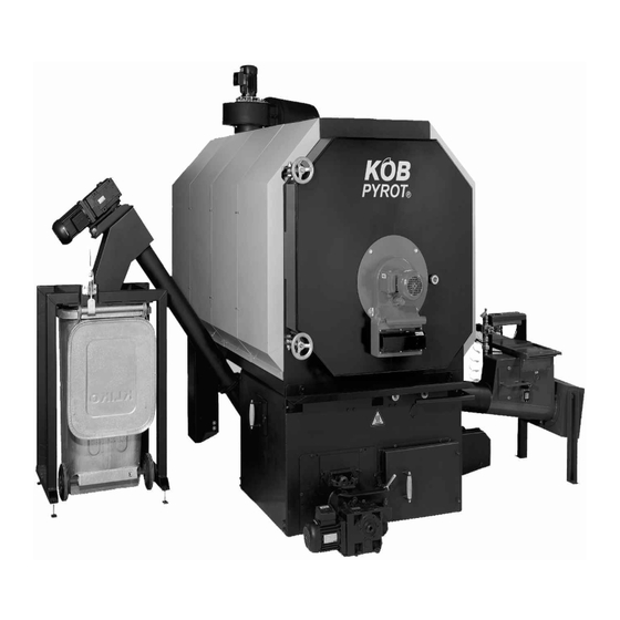
Page 15: How The Boiler Plant Is Strucured
3 How the Boiler Plant is Strucured (Illustration: PYROT 300) (1) Feed auger with isolating layer (8) Rotation combustion chamber (Viessmann-pat ented) (2) Drive for moving grate (9) Boiler heat exchanger (3) Automatic ignition device (10) Boiler door (4) Controlled combustion air supply system (11) Heat exchanger for thermal run-off safety valve (5) Moving grate (12) Speed-controlled exhaust fan... -
Page 16: Commissioning/Operation
4.2 Operation 4 Commissioning/Operation 4.2.1 Heating up 4.1 The initial start-up Press the F1 key "PYROT Wood". The loader modules Only Viessmann or another trained specialist may put a will be switched on in the appropriate order. When newly installed facility into operation for the first time. there is enough fuel in the combustion chamber, the entire loader system switches off. -
Page 17: The Ecotronic Control System
Factory settings (pre-settings) 5 The ECOTRONIC control system All the parameters in the ECOTRONIC, such as set point values and switching times, are pre-set and can be called back up at any time. The figures for the factory settings are given in brackets for the various parameters. 5.1.1 Replacing the battery There is a battery built in beneath the removable lid on the control module (type:... -
Page 18: Boiler And Loader System (F3/F4)
5.3 Boiler and loader system (F3/F4) (10) Load storage unit with oil/gas operation to (storage unit at bottom): 5.3.1 The F3 KEY: "PYROT Parameters" To which heat storage sensor should the storage unit be loaded with oil/gas operation? (screen number) parameter (factory setting) (Indication only with option of storage unit and oil/gas burner on PYROT ECO) (01) Storage unit temperatures ( - ):... -
Page 19: The F4 Key: "Pyrot Loader System
(e.g. spring-operated extraction system, inclined extraction (40) Enter permanent code (-): system, etc.) (41) Measurement operation (NO): This activates measurement operation for chimney sweep (39) Extraction System 1/Impulse (5 s): measurements. Impulse for the cycle switching for Extraction System 1 IMPORTANT: The control of output is then not function- (e.g. -
Page 20: Extended Control Systems F5 - F8 (Optional)
5.4 Extended control systems F5 – F8 (optional) (04) Heating Period 1/Start (6:00) The F5 to F8 keys are assigned customer-specific ex- Time to switch from lowered temperature (or off) to nor- tended control systems as desired. Each extended control mal temperature. - Page 21 The heating curve Room thermostat (ECO-ZR-QA): The correspondence of the flow temperature to the out- The Model QAA 35 Room Thermostat can be used with or door temperature can be set directly and read directly. The without influence by the room temperature. setting is carried out by two points: Switch positions possible: Point 1:...
-
Page 22: Utility Water Heater
5.4.2 Utility water heater (screen number) parameter (factory setting) Function: ECO-B1 (01) Operating mode (timer) When the temperature of the utility water drops, it is Select operating mode reheated by the built-in heat exchanger from the heat accumulator (hydraulic switcher). The condition for this (02) Number of heating periods (1) is a relevant difference in temperature (choice of con- The weekly programme has to be entered in the form of... -
Page 23: Air Heater
5.4.3 Air heater Function (ECO-L): (05) Heating Period 1/End (22:00) Time to switch off air heater. The air heaters are supplied at maximum flow temperature from the boiler plant storage system. The fans are con- (06-23) Heating Periods 2-7 nected by switches or controllers provided by the cus- These depend on the number of heating periods (see Mask tomer. -
Page 24: Annex Buildings
5.4.4 Annex buildings Function (ECO-N): (04) Heating Period 1/Start (6:00) Time to switch from lowered temperature (or off) to nor- The pipeline is usually supplied with a lowered tempera- mal temperature. ture required by the weather-guided heating control sys- tem. The utility water heater is loaded at the maximum (05) Heating Period 1/End (22:00) flow temperature set. -
Page 25: Pipelining
The heating curve 5.4.5 Pipelining See "Extended control system for room heating unit" Function (ECO-F): Room thermostat (ECO-ZR-QA): This is for an annex building with a separate heat distribu- See "Extended control system for room heating unit" tion system, which is supplied with heat via a pipeline. Operating modes of the utility water heater: According to prompts by the heat distribution system, the temperature of the pipeline is pre-adjusted for the lowest... -
Page 26: Additional Heat Generator
(10) Load storage unit to (70°C): 5.4.4 Additional heat generator To what temperature on the accumulator sensor selected Function (ECO-KP1): should the additional heat generator heat up the accumula- tor? The additional heat generator is automatically connected (Indication only with accumulator option) when required. -
Page 27: Solar
5.4.5 Solar Operating modes Function (ECO-S1): This is used in simple solar systems with a single control Off: Pump off; valve shut circuit to heat the utility water in the solar utility water Automatic: heater (Art. No: WSS-___). The ECO-S1 controller is an Automatic heating of the solar utility water heater and additional component for the ECO-B1(2) controller for the of the accumulator by means of difference-based con-... -
Page 28: Cleaning/Maintenance
Cleaning/Maintenance 6.1 Boiler The heat exchanger, flue pipe, and chimney must be cleaned regularly to remove accumulated creosote and ash. Ensure that the heating exchanger, flue pipe, and chimney are cleaned at the end of the heating season to minimize corrosion during the summer months. - Page 29 Pneumatic tube-cleaning system (optional) Exhaust gas deduster, detached (optional) After approx. 1000 operating hours: Unplug the plug, unscrew butterfly nuts, pull out motor with impeller and clean with broom or wire brush. CAUTION: DANGER OF INJURY – be abso- lutely sure to switch off master switch. After each cleaning of the set of tub- Open lid and clean the guide blades of the de-duster with hand-brush.
-
Page 30: Installing The Displacement Rods Into The Heat Exchanger
6.2 Installing the displacement rods into the heat exchanger The displacement rods improve the heat transmission in the heat exchanger and reduce the temperature of the exhaust gas, thus improving the efficiency of the heating system. They are taken out to clean the heat exchanger tubes and then put back Insert the displacement rods into the heat exchanger tube with the thick end first. -
Page 31: Feed Systems
6.3 Feed systems Control system When storage facilities for wood are required the wood Even when the PYROT is put out of operation for long pe- should be kept at least 1.5m (5ft) from the heating appli- riods, the power supply to the control system should not ance. - Page 32 vIESmAnn Spec Sheet Wood Fuels 1010-d-1 Minimum Requirements/ Information A prerequisite for approval is the express permission for such by the public authority responsible. For claims to the warranty according to Section 11 of our General Terms and Conditions of Delivery, wood fuels have to meet the following conditions. If those conditions are not met, then approval is possible with restrictions (warranty, maintenance, operational safety) with a written statement by the manufacturer in reference to the facility.
- Page 33 vIESmAnn Spec Sheet Wood Fuels 1010-d-2 Minimum Requirements/ Information 5) Bulk density S (kg/m³), water content W (%), size G (mm) Bulk density S in kg/m³ (lb/ft3), water content W in %, size C1, C3, C4, C5,P1, P2, P3 as per CAN/CSA-B366.1-M91 In biomass boiler plants, the wood fuels that will be used are to be individually listed as follows: S 130 (8.1) W10 to W20 C1 Sawdust, untreated (planing shop) S 200 (12.5) W20 to W35 C1 Sawdust, untreated (sawmill)
- Page 34 Malfunction report / malfunction remedy Heat Generation Text displayed for mal- Malfunction alarm Possible cause Check / Remedy function - Temperature-limiting safety switch N21 - In correct setting on the control module - Why could the heat not be dissipated? Excess temperature (F1, F2, F3 lights up red) (TLSS) up at the burner.
- Page 35 Malfunction report / malfunction remedy Loader System Text displayed for mal- Malfunction alarm Possible cause Check / Remedy function Material shortage - Light barrier in the metering container - Silo is empty - Fill silo (F4 lights up red) - Light barriers for the ember monitoring - Material clogged -Switch off master switch and undo material clogging system...
- Page 36 Viessmann Manufacturing Company Inc. Viessmann Manufacturing Company (U.S.) Inc. 750 McMurray Road 45 Access Road Waterloo, Ontario N2V 2G5 Canada Warwick, Rhode Island 02886 USA Tel. (519) 885-6300 Fax (519) 885-0887 Tel. (401) 732-0667 Fax (401) 732-0590 www.viessmann.ca info@viessmann.ca www.viessmann-us.com info@viessmann-us.com...
Need help?
Do you have a question about the PYROT KRT 150 and is the answer not in the manual?
Questions and answers