Table of Contents
Advertisement
VENSTAR
F
C
AN
OIL
T
HERMOSTAT
3 Occupied, 1 Unoccupied
Override capable
3 speed fan control
Auto 2-pipe changeover
when used with accessory
changeover sensor
Dry contact equipped
Backlit display
OWNER'S MANUAL
INSTALLATION INSTRUCTIONS
F
AN
T
HERMOSTAT
T1075
7 D
AY
P
ROGRAMMABLE
2
4
OR
PIPE
SYSTEMS
Works with most fan
coil systems - 24vac
Electric heat ready
Non-volatile memory
Dual or single setpoint
Remote sensor ready
Display F or C
AND
C
OIL
Advertisement
Table of Contents

Related Manuals for Venstar T1075


Summary of Contents for Venstar T1075
- Page 1 VENSTAR HERMOSTAT T1075 HERMOSTAT ROGRAMMABLE PIPE SYSTEMS 3 Occupied, 1 Unoccupied Works with most fan coil systems - 24vac Override capable 3 speed fan control Electric heat ready Auto 2-pipe changeover Non-volatile memory Dual or single setpoint when used with accessory...
- Page 2 ADVANCED SETUP TABLE ABOUT ADVANCED FEATURES & OPERATION SAMPLE WIRING DIAGRAMS WARRANTY CAUTION Disconnect Power to the Heater/Air Conditioner before removing the old therm- ostat and installing the new WARNING thermostat. Model T1075 Copyright 2012 Venstar, Inc All Rights Reserved Page 1...
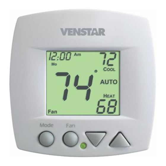
- Page 3 Front Panel I2:00 AUTO Mode Liquid Crystal Display Up/Down Buttons Mode Button Fan/Override Button Heat or Cool Indicator Heat = Red, Cool = Green Page 2...
- Page 4 Display UTSIDE Mode Indicators - Pages 7-10 Selects the operational mode of the equipment. HEAT - Indicates the heating mode. COOL - Indicates the cooling mode. AUTO - Indicates the system will automatically changeover between heat and cool modes as the temperature varies. PROGRAM ON - Indicates the time period program is enabled to run.
- Page 5 Display I2:00 Start Stop SuMoTuWeThFrSa Setup unoccupied Locked Override AUTO UTSIDE Override icon - Pages 12 & 22 Indicates the program is currently being overridden for up to six hours. Occupied & Unoccupied icons - Pages 13-16 Indicates the program number: Occupied 1,2,3 or Unoccupied.
- Page 6 Display I2:00 Start Stop SuMoTuWeThFrSa Setup unoccupied Locked Override AUTO UTSIDE Start & Stop icons - Pages 14-16 Appear when programming occupied time periods. Locked icon - Page 31 Indicates keypad has been locked. Outside icon - Page 32 Indicates the temperature displayed is from the optional outside sensor.
- Page 7 Quick Start Set the Clock and Go Press the MODE and FAN buttons MODE at the same time for two seconds to enter Setup screens. During Setup and Programming: Pressing the UP or Setting the Clock DOWN button will Tip: To change modify the flashing I2:00 hours quickly,...
- Page 8 Selecting the Heat or Cool Mode 4-Pipe Operation Select Mode by Pressing the MODE Button I2:00 Heating Only The HEAT setting indicates the temperature the room has to reach before the Press heating source will turn on to heat the room. MODE I2:00 Cooling Only...
- Page 9 Selecting the Heat or Cool Mode 2-Pipe Operation Heat Only Step #6 = 1 in the Advanced Setup section, page 19. I2:00 Heating Only The HEAT setting indicates the temperature the room has to reach before the heating source will turn on to heat the room.
- Page 10 Selecting the Heat or Cool Mode 2-Pipe Operation Cool Only Step #6 = 2 in the Advanced Setup section, page 19. I2:00 Cooling Only The COOL setting indicates the temperature the room has to reach before the cooling source will turn on to cool the room.
- Page 11 Selecting the Heat or Cool Mode 2-Pipe Operation Heating and/or Cooling Step #6 = 3 in Advanced Setup (page 19), and the accessory changeover sensor (ACC-SENFC) is used. Step #6 = 4 or 5 in Advanced Setup (page 19). Operation is the same as a 4-pipe system (page 7). I2:00 HEAT indicates the temperature the room has to reach before the...
- Page 12 Basic Operation Selecting Your Desired Temperature (adjusting the setpoints) AUTO OR PROGRAM MODE Pressing the UP or DOWN button when both Heat & Cool setpoints are visable will adjust both the heat and cool set temperatures simultaneously. I2:00 Adjust the desired set temperature with the AUTO buttons.
- Page 13 Basic Operation Overriding the Daily Schedule Pressing and holding the FAN button for 5 seconds may be used to interrupt the normal time schedule programming of the thermostat. The override feature may only be used when the thermostat is running the time schedule, in Program On mode.
- Page 14 Programming Occupied & Unoccupied Periods Press the MODE button. While holding MODE, press the UP button for two MODE seconds to enter time period programming. Select the maximum # of occupied periods to be occupied used on any one day. Typically, most installations use only Occupied 1.
- Page 15 Programming Occupied & Unoccupied Periods Adjust the heating set- unoccupied point for Unoccupied periods. (OF, 35 - 99 ) Press MODE Select day of the occupied week to program. (Mo - Su) Press MODE 7:00 Start occupied Adjust the start time for Occupied 1.
- Page 16 Programming Occupied & Unoccupied Periods The copy command becomes available after the maximum # of occupied periods are programmed in a day. This example uses 1 as the maximum occupied periods ever programmed in one day. Select Yes or No to copy t h e p r e v i o u s d a y ’s program to this day.
- Page 17 Programming Occupied & Unoccupied Periods 5:00 Stop occupied Adjust the stop time for occupied 1. Select Occupied 1 to occupied run on this day (On), or not to run this day (Off). Press MODE Select Yes or No to copy the previous day’s program to this day.
- Page 18 Programming Occupied & Unoccupied Periods PROGRAMMING NOTES You will be prompted to enter both heat and cool setpoints even if the thermostat is configured for heat only, or cool only. If only 1 Occupied period is selected, the Occupied 2 & 3 steps will be skipped.
- Page 19 Advanced Setup NOTE: Each step Press the MODE and MODE # is located at the FAN buttons at the top right corner of same time for 10 the display for easy seconds to enter reference. A d v a n c e d S e t u p screens.
- Page 20 Advanced Setup Select Display operation: Setup 1 = Single Setpoint 2 = Dual Setpoint See Page 33 Note: When Single Setpoint is selected, the heating or cooling setpoint will always be displayed. To display the room temperature, press and hold the MODE Press button for two seconds.
- Page 21 Advanced Setup Select operation when fan is in the Auto mode: On = continuous low speed fan AUTO Off = only energize during a heating or cooling cycle. Press See Page 29, Note #2 MODE Select Fan Coil Type On = Carrier or IEC fan coil using a 33ZCRLYBRD relay board.
- Page 22 Advanced Setup Step #10 will not appear if step #6 = 1 or 2. Adjust the minimum Setup difference between cooling & heating setpoints. (0 - 6 ) Press MODE Setup Select backlight operation: On - Light continuously Off - Light for 8 seconds after a button press Press MODE...
- Page 23 Advanced Setup 2 00 Adjust the amount of Setup time override will be a c t i v e d u r i n g t h e Override unoccupied time period. (0 - 6 hours) Press MODE Setup Dry Contact NO = Normally Open NC = Normally Closed Press...
- Page 24 Advanced Setup Unoccupied Setpoints Setup unoccupied Select Dry Contact Unoccupied operation: Unoccupied = when the Dry Contact is closed, the thermostat will con- trol to the Unoccupied setpoints. Off = when the Dry Contact is closed, the thermostat will turn off.
- Page 25 Advanced Setup Advanced Setups - Table Step Description Range Default Time of Day 24 Hour 12:00am Mo - Su Day of Week Display Blanking On / Off Single or Dual Setpoint 1 /2 2 or 4 Pipe System 2 / 4 2 Pipe System Operation 1 - 5 Fan Auto Operation...
- Page 26 About Advanced Features & Operation CALIBRATION - Under normal circumstances it will not be necessary to adjust the calibration of the temperature sensor. If calibration is required, please contact a trained HVAC technician to correctly perform the following procedure. I2:00 MODE Place the thermostat in the OFF mode.
- Page 27 About Advanced Features & Operation DEADBAND OPERATION - Controls one Heat and one Cool stage with a three speed fan (see below). The low speed fan for heat or cool is turned on when: The temperature spread from the setpoint is equal to or greater than: the setpoint plus the 1st stage dead- band (step #9, page 20).
- Page 28 Important Note: For control of multiple thermostats by 1 source, refer to page 37 ‘Potential Phasing Problems’ before installation. TERMINAL CONNECTIONS RS+5 Y1 G3 W1 H2O CK1 MODEL: T1075 X072500204 ENCLOSED ENERGY 4Z95 24V. 60HZ MANAGEMENT NEC CLASS 2 EQUPIMENT...
- Page 29 About Advanced Features & Operation FACTORY DEFAULTS - If, for any reason, you desire to return all the stored settings back to the factory default settings, follow the instructions below. WARNING: This will reset all Time Period and Ad- vanced Programming to the default settings. Any information entered prior to this reset will be permanently lost.
- Page 30 About Advanced Features & Operation FAN OPERATION - Fan operation is available in four different modes: Fan: When only the fan icon is displayed, this indicates that the fan is in the Auto mode, will only energize during a heating or cooling cycle, and will modulate fan speeds based on temperature demand (see page 26).
- Page 31 About Advanced Features & Operation ENERGY SAVING SMART FAN - This feature auto- matically de-energizes the fan during an Unoccupied time period, except when necessary to heat or cool (see page 29). I2:00 unoccupied Note: The fan will not de-energize during an Un- occupied time period if it has been programmed for continuous operation (step #7, page 20).
- Page 32 About Advanced Features & Operation KEYPAD LOCKOUT - To prevent unauthorized use of the thermostat, the front panel buttons may be disabled. To disable, or ‘lock’ the keypad, press and hold the MODE button. While holding the MODE button, press the UP and DOWN buttons together.
- Page 33 About Advanced Features & Operation OUTSIDE SENSOR - To view an Outside Sensor (step #13, page 21), enter the Advanced Setup by pressing and holding the MODE button. While holding MODE, press the FAN button for 5 seconds to enter Setup screens. Advance to setup step #13 by repeatedly pressing the MODE button.
- Page 34 About Advanced Features & Operation SINGLE SETPOINT BEHAVIOR - When configured for Single Setpoint operation (step #4, page 19), the degree icon will blink when the large number is display- ing room temperature and will remain solid when dis- playing the heating or cooling setpoint. In the Auto and Program On modes the deadband is enforced both above and below the setpoint.
- Page 35 Sample Wiring Diagram 2-Pipe, Low Voltage Valve, H2O Changeover Sensor Thermostat If 2-pipe with auxiliary electric heat 24vac 24 Volt Water Valve Generic Relay Board LO (L1) G2/(W) G3/(Y) L1 (N/A) HI (HI) MED (MED) H O Changeover Sensor ACC-SENFC Page 34...
- Page 36 Sample Wiring Diagram 4-Pipe, Low Voltage Valves, Duct Temperature Sensor & Dry Contact Duct Sensor Important Note: If a ACC0402 Duct sensor is conn- ected to this thermostat it is suggested that the fan be programmed for RS GND continuous operation (step #7, page 20 of the Owner’s Manual).
- Page 37 Sample Wiring Diagram Connection Diagram for Duct Sensor to T1075 Fan Coil Thermostat Digital Sensor High Temp. Heat Shrink Tubing 5’ Plenum Rated Cable White Black Note: It is important to connect the black wire from the Duct Sensor directly to the R terminal on the thermostat backplate.
- Page 38 Sample Time Clock Wiring Diagram Important Information About: Auxiliary Input Control and Multiple HVAC Control Potential Phasing Problems CAUTION WARNING When using the auxiliary input (CK1 & R) or controlling multiple HVAC units with a single thermostat, it is possible to encounter transformer phasing problems that will interfere with thermostat operation.
- Page 39 This warranty gives you specific legal rights and you may also have other rights which may vary from state to state. P/N 88-948 T1075 OWNERS & INSTALLATION MANUAL Rev. 1...
Need help?
Do you have a question about the T1075 and is the answer not in the manual?
Questions and answers