Advertisement
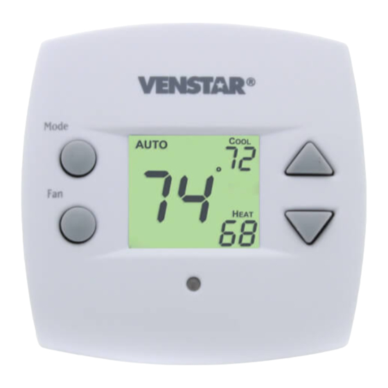
Digital
Digital
Thermostat
Thermostat
HEAT
HEAT
COOL
PUMP
Use with most Air Conditioning & Heating Systems including: 1 or 2 Stage
Electric Cooling & 2 Stage Gas Heating, Heat Pump, Electric or Hydronic Heat.
INSTALLATION
INSTALLATION
INSTRUCTIONS
INSTRUCTIONS
Venstar Inc. 08/07
residential
THERMOSTAT
T1010
Single Day
Single Day
PROGRAMMABLE
PROGRAMMABLE
up to
2-heat
up to
2-heat
& 2-cool
& 2-cool
Control up to 2 Heat &
2 Cool Stages
HP Stages: 2 Heat, 2 cool
Single Day Programmable
4 Settings Per Day
Auto Changeover
5 min. Built-In Compressor
Protection
Back-Lit Display
One For All Works with
Virtually All Equipment
'O' or 'B' Terminal
Non-Volatile Memory
Keypad Lockout
Display Either F or C
Advertisement

Related Manuals for Venstar T1010


Summary of Contents for Venstar T1010
- Page 1 Keypad Lockout Display Either F or C Use with most Air Conditioning & Heating Systems including: 1 or 2 Stage Electric Cooling & 2 Stage Gas Heating, Heat Pump, Electric or Hydronic Heat. INSTALLATION INSTALLATION INSTRUCTIONS INSTRUCTIONS Venstar Inc. 08/07...
-
Page 2: Table Of Contents
AIR CONDITIONER BEFORE REMOVING THE OLD THERMOSTAT AND INSTALLING WARNING THE NEW THERMOSTAT. Venstar Inc. 08/07 P/N T1010 This device complies with Part 15 of the FCC rules. Operation is subject to the following two conditions: (1) This device may not cause harmful interference, and (2) this device must accept any interference received, including interference that may cause undesired operation. -
Page 3: Step #1: Preparation
STEP #1 PREPARATION Proper installation of the thermostat will be AUTO accomplished by following these step by step instructions. If you are unsure about any of these steps, call a qualified technician for assistance. Assemble tools. AUTO Drill with 3/16 inch Drill Bit Flat Blade Wire cutter... -
Page 4: Step #2 Remove & Replace Old Thermostat
STEP #2 REMOVE & REPLACE OLD THERMOSTAT Remove the cover of the old thermostat. AUTO If it does not come off easily check for screws. Loosen the screws holding the thermostat AUTO base or subbase to the wall, and lift away. Disconnect the wires from the old AUTO thermostat. -
Page 5: Step #3 Wire Connections
STEP #3 WIRE CONNECTIONS If the terminal designations on your old AUTO thermostat do not match those on the new thermostat, refer to the chart below, or the wiring diagrams that follow. I n s t a l l t h e Wire from the thermostat thermos tat... -
Page 6: Sample Wiring Diagrams
Sample Wiring Diagrams Sample Wiring Diagrams Gas or Electric Heat 5 Wire, 1 Stage Cooling, 1 Stage Gas Heat Residential Gas or Electric Heat*, Electric Cool, split systems & package units Y1 W2 W1 POWER COMPRESSOR GAS VALVE STRIP HEAT COMMON * If using first stage electric heat, this option must be selected ON (see page 11, step #6 of Owner’s Manual). - Page 7 Sample Wiring Diagrams Gas or Electric Heat 4 Wire, 1 Stage Cooling, 1 Stage Gas Heat Residential Gas or Electric Heat*, Electric Cool, split systems & package units Y1 W2 W1 POWER COMPRESSOR GAS VALVE STRIP HEAT * If using first stage electric heat, this option must be selected ON (see page 11, step #6 of Owner’s Manual).
- Page 8 Sample Wiring Diagrams Gas or Electric Heat 6 Wire, 2 Stage Cooling, 1 Stage Gas Heat Residential two stage cooling with Gas or Electric Heat*. Y1 W2 W1 Y2 POWER COMPRESSOR GAS VALVE STRIP HEAT 2nd STAGE COOLING COMMON * If using first stage electric heat, this option must be selected ON (see page 11, step #6 of Owner’s Manual).
- Page 9 Sample Wiring Diagrams Gas or Electric Heat 6 Wire, 1 Stage Cooling, 2 Stage Heat Residential & commercial 1 Stage Cooling, with 2 Stage Gas or Electric Heat* Y1 W2 W1 Y2 POWER COMPRESSOR 2nd STAGE HEATING GAS VALVE STRIP HEAT COMMON * If using first stage electric heat, this option must be selected ON (see page 11, step #6 of Owner’s Manual).
- Page 10 Sample Wiring Diagrams Gas or Electric Heat Commercial Gas or Electric Heat *, 7 Wire, 2 Stage Cooling, 2 Stage Heat Electric Cool, split systems & package units including Commercial Heat Pumps ** Y1 W2 W1 Y2 POWER COMPRESSOR 2nd STAGE HEATING GAS VALVE STRIP HEAT...
-
Page 11: Heat Pump
Sample Wiring Diagrams Heat Pump 5 Wire, 1 Stage Cooling, 1 Stage Heat-Heat Pump* with O or b reversing valve**. Residential Heat Pumps, split systems & package units, with no auxiliary heat. Y1 W2 W1 POWER COMPRESSOR REVERSING VALVE** COMMON * This option must be selected ON during advanced setup (see page 11, step #4 of Owner’s Manual). - Page 12 Sample Wiring Diagrams Heat Pump 6 Wire, 1 Stage Cooling, 2 Stage Heat-Heat Pump* with O or b reversing valve**. Residential Heat Pumps, split systems & package units, with auxiliary heat. Y1 W2 W1 Y2 POWER COMPRESSOR 2nd STAGE HEATING REVERSING VALVE** COMMON * This option must be selected ON during advanced setup...
-
Page 13: Step #4: Test Operation
STEP #4 TEST OPERATION Turn the power on to the Heating/Air AUTO Conditioning system. Press the MODE button repeatedly until AUTO the HEAT icon appears on the display. Press the UP or DOWN buttons until the set temperature is 10 degrees above room temperature. -
Page 14: Troubleshooting
TROUBLESHOOTING SYMPTOM: When using 4 wires (R, G, W, Y), AUTO the air conditioning equipment tries repeatedly to turn on, but cannot. At times the display dims or disappears. CAUSE: There is not enough power available to "power share". REMEDY: Connect a 270 ohm, 10 watt power resistor at the furnace as shown below. - Page 15 "conventional" (non-heat pump) system. REMEDY: See page 11 of the Owner's Manual and set step #4 to OFF to enable gas electric operation. STAR T1010 Tested to Comply with FCC Standards FOR HOME OR OFFICE USE 4Z95 P/N 88-608 Rev.
Need help?
Do you have a question about the T1010 and is the answer not in the manual?
Questions and answers