Advertisement
Digital
Digital
Thermostat
Thermostat
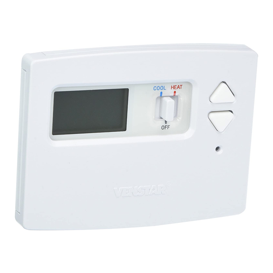
Stages: 1-Heat, 1-Cool
Battery or System Powered
Back-Lit Digital Display
Fahrenheit or Celsius
Service Filter Indicator
Bi-Color LED
(when system powered)
Use with most Air Conditioning & Heating Systems including: 1 Stage
Electric Cooling & 1 Stage Gas Heating, Heat Pump, Electric or Hydronic Heat.
INSTALLATION
INSTALLATION
INSTRUCTIONS
INSTRUCTIONS
Venstar Inc. 05/08
residential
THERMOSTAT
T1035
5+2 DAY
5+2 DAY
PROGRAMMABLE
PROGRAMMABLE
up to
1-heat
up to
1-heat
& 1-cool
& 1-cool
HEAT
HEAT
COOL
PUMP
Advertisement
Table of Contents
Troubleshooting

Related Manuals for Venstar T1035


Summary of Contents for Venstar T1035
- Page 1 Fahrenheit or Celsius Service Filter Indicator Bi-Color LED (when system powered) Use with most Air Conditioning & Heating Systems including: 1 Stage Electric Cooling & 1 Stage Gas Heating, Heat Pump, Electric or Hydronic Heat. INSTALLATION INSTALLATION INSTRUCTIONS INSTRUCTIONS Venstar Inc. 05/08...
-
Page 2: Table Of Contents
INSTALLATION INSTRUCTIONS T1035 Contents Page # Safety Warnings Preparation Remove Old Thermostat Battery Replacement Wire Connections Jumper Configuration Test Operation Troubleshooting Warranty Page 2... -
Page 3: Safety Warnings
INSTALLATION INSTRUCTIONS T1035 Safety Warnings P/N 1035 Follow Installation Instructions carefully. CAUTION DISCONNECT POWER TO THE HEATER - AIR CONDITIONER BEFORE REMOVING THE OLD THERMOSTAT AND INSTALLING WARNING THE NEW THERMOSTAT. CAUTION The two Alkaline “AA” batteries must be replaced at least once every 12 months to ensure proper operation. -
Page 4: Preparation
INSTALLATION INSTRUCTIONS T1035 Preparation Proper installation of the thermostat will be I2:00 accomplished by following these step by step instructions. If you are unsure about any of these steps, call a qualified technician for assistance. These tools will be required:... -
Page 5: Remove Old Thermostat
INSTALLATION INSTRUCTIONS T1035 Remove & Replace Old Thermostat Remove the cover of the old thermostat. I2:00 If it does not come off easily check for screws. Loosen the screws holding the thermostat I2:00 base or subbase to the wall, and lift away. -
Page 6: Battery Replacement
INSTALLATION INSTRUCTIONS T1035 Battery Replacement The batteries are easily accessible from the battery slot located on the front of the thermostat (fig. 1). To open the battery slot, press down on the battery cover (fig. 1) and pull out (fig. 2). -
Page 7: Wire Connections
INSTALLATION INSTRUCTIONS T1035 Wire Connections If the terminal designations on your old I2:00 thermostat do not match those on the new thermostat, refer to the chart below or the wiring diagrams that follow. Install on the Wire from the new thermostat... -
Page 8: Sample Wiring Diagrams
INSTALLATION INSTRUCTIONS T1035 Sample Wiring Diagrams Gas or Electric Heat 4 Wire, 1 Stage Cooling, 1 Stage Heating Residential Gas or Electric Heat, Electric Cool, split systems & package units. For jumper configuration see pages 14 and 15. Factory installed... - Page 9 INSTALLATION INSTRUCTIONS T1035 Sample Wiring Diagrams Gas or Electric Heat 4 Wire, 1 Stage Cooling, 1 Stage Heating-Heat Pump with O reversing valve. Residential Heat Pumps, split systems & package units, with no auxiliary heat. For jumper configuration see page 16.
- Page 10 INSTALLATION INSTRUCTIONS T1035 Sample Wiring Diagrams Gas or Electric Heat 4 Wire, 1 Stage Cooling, 1 Stage Heating-Heat Pump with B reversing valve. Residential Heat Pumps, split systems & package units, with no auxiliary heat. For jumper configuration see page 17.
- Page 11 INSTALLATION INSTRUCTIONS T1035 Sample Wiring Diagrams Gas or Electric Heat 3 Wire, 1 Stage Heating Residential Gas or Electric Heat units with a separately controlled fan. For jumper configuration see pages 14 and 15. Factory installed Common wire optional jumper between...
- Page 12 INSTALLATION INSTRUCTIONS T1035 Sample Wiring Diagrams Gas or Electric Heat 2 Wire, 1 Stage Gas Heat Residential Gas or Millivolt units. For jumper configuration see page 14. Factory installed Common wire optional jumper between RC and RH 2 Conductor 18 to 22 gauge unshielded cable from the thermostat to the equipment.
- Page 13 INSTALLATION INSTRUCTIONS T1035 Sample Wiring Diagrams Gas or Electric Heat Dual Transformer 5 Wire, 1 Stage Cooling, 1 Stage Heating Residential Gas or Electric Heat, Electric Cool, split systems & package units. For jumper configuration see pages 14 and 15.
-
Page 14: Jumper Configuration
T1035 Jumper Configuration Cooling and Gas Heating Residential Gas, Electric Cool, split systems & package units. PCB: 00597 Rev. AA PCA: 00569 Rev. 1000 1000 MODEL: T1035 082100009 1000 GAS/ELEC ELEC/HP BAT- BAT+ GAS/ELEC GAS/ELEC ELEC/HP Jumper #1 (J1) should be set for GAS and... - Page 15 INSTALLATION INSTRUCTIONS T1035 Jumper Configuration Cooling and Electric Heating Residential Electric Heat units with a separately controlled fan. PCB: 00597 Rev. AA PCA: 00569 Rev. 1000 1000 MODEL: T1035 082100009 1000 GAS/ELEC ELEC/HP BAT- BAT+ ELEC/HP GAS/ELEC GAS/ELEC ELEC/HP Jumper #1 (J1) should be set for ELEC/HP and...
- Page 16 Cooling and Heating - Heat Pump with O reversing valve. Residential Heat Pumps, split systems & package units, with no auxiliary heat. PCB: 00597 Rev. AA PCA: 00569 Rev. 1000 1000 MODEL: T1035 082100009 1000 GAS/ELEC ELEC/HP BAT- BAT+ ELEC/HP...
- Page 17 Cooling and Heating - Heat Pump with B reversing valve. Residential Heat Pumps, split systems & package units, with no auxiliary heat. PCB: 00597 Rev. AA PCA: 00569 Rev. 1000 1000 MODEL: T1035 082100009 1000 GAS/ELEC ELEC/HP BAT- BAT+ ELEC/HP...
-
Page 18: Test Operation
INSTALLATION INSTRUCTIONS T1035 Test Operation Turn on the power to the Heating/Air I2:00 Conditioning system. On the thermostat, slide the Mode Switch I2:00 to HEAT. Press the COOLER or WARMER button until the set temperature is 10 degrees above room temperature. The HVAC unit should energize in the heating mode. -
Page 19: Troubleshooting
INSTALLATION INSTRUCTIONS T1035 Trouble Shooting SYMPTOM: The slide switches on the thermostat I2:00 are very difficult to move. CAUSE: The backplate of the thermostat is screwed too tightly into a wall that is not perfectly flat. REMEDY: Loosen the screws holding the thermostat into the wall. - Page 20 INSTALLATION INSTRUCTIONS T1035 Trouble Shooting SYMPTOM: The Heating does not attempt I2:00 to turn on. CAUSE: The heating setpoint is set too high, the Mode Switch is not set for Heat, or the batteries are too weak. REMEDY: Consult the Normal Operation section in the Owner’s Manual to:...
-
Page 21: Warranty
INSTALLATION INSTRUCTIONS T1035 Warranty One-Year Warranty - This Product is warranted to be free from defects in material and workmanship. If it appears within one year from the date of original installation, whether or not actual use begins on that date, that the product does not meet this warranty, a new or remanufactured part, at the manufacturer’s sole option to replace any defective part, will be...
Need help?
Do you have a question about the T1035 and is the answer not in the manual?
Questions and answers