Advertisement
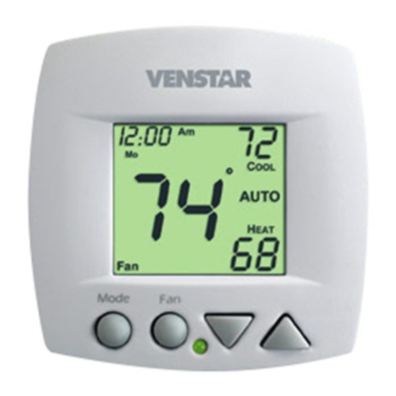
VENSTAR
F
C
AN
OIL
T
HERMOSTAT
Remote sensor ready
3 speed fan control
Self-prompting adjustment
Auto 2-pipe changeover
when used with
ACC-SENFC
changeover sensor
Dry contact equipped
Backlit display
OWNER'S MANUAL
INSTALLATION INSTRUCTIONS
F
AN
T
HERMOSTAT
T1070
N
-
ON
P
ROGRAMMABLE
2
4
OR
PIPE
SYSTEMS
Works with most fan
coil systems - 24vac
Electric heat ready
Non-volatile memory
Dual setpoint with
adjustable deadband
Keypad lockout
Configurable display
Display F or C
AND
C
OIL
Advertisement
Table of Contents

Related Manuals for Venstar T1070


Summary of Contents for Venstar T1070
- Page 1 VENSTAR HERMOSTAT T1070 HERMOSTAT ROGRAMMABLE PIPE SYSTEMS Works with most fan Remote sensor ready coil systems - 24vac Electric heat ready 3 speed fan control Self-prompting adjustment Non-volatile memory Auto 2-pipe changeover Dual setpoint with adjustable deadband when used with...
-
Page 2: Table Of Contents
ADVANCED SETUP TABLE ABOUT ADVANCED FEATURES & OPERATION SAMPLE WIRING DIAGRAMS WARRANTY CAUTION Disconnect Power to the Heater/Air Conditioner before removing the old therm- ostat and installing the new WARNING thermostat. Model T1070 Copyright 2012 Venstar, Inc All Rights Reserved Page 1... -
Page 3: Front Panel
Front Panel AUTO Mode Liquid Crystal Display Up/Down Buttons Mode Button Fan Button Heat or Cool Indicator Heat = Red, Cool = Green Page 2... -
Page 4: Display
Display unoccupied UTSIDE Mode Indicators - Page 5-8 Selects the operational mode of the equipment. HEAT - Indicates the heating mode. COOL - Indicates the cooling mode. AUTO - Indicates the system will automatically changeover between heat and cool modes as the temperature varies. - Page 5 Display unoccupied UTSIDE icon - Page 9 Indicates fan operation. = low speed = medium speed = high speed When only the Fan icon is displayed, the fan is in the Auto mode and will run only when necessary to heat or cool.
-
Page 6: Selecting The Heat Or Cool Mode
Selecting the Heat or Cool Mode 4-Pipe Operation Select Mode by Pressing the MODE Button Heating Only The HEAT setting indicates the temperature the room has to reach before the heating source will turn on to heat the room. Press MODE Cooling Only The COOL setting indicates... - Page 7 Selecting the Heat or Cool Mode 2-Pipe Operation Heat Only Step #4 = 1 in the Advanced Setup section, page 11. Heating Only The HEAT setting indicates the temperature the room has to reach before the heating source will turn on to heat the room.
- Page 8 Selecting the Heat or Cool Mode 2-Pipe Operation Cool Only Step #4 = 2 in the Advanced Setup section, page 11. Cooling Only The COOL setting indicates the temperature the room has to reach before the cooling source will turn on to cool the room.
- Page 9 Selecting the Heat or Cool Mode 2-Pipe Operation Heating and/or Cooling Step #4 = 3 in Advanced Setup (page 11), and the accessory changeover sensor (ACC-SENFC) is used. If step #4 = 4 or 5 in Advanced Setup (page 11). Operation is the same as a 4-pipe system (page 5).
-
Page 10: Basic Operation
Basic Operation Selecting Your Desired Temperature (adjusting the setpoints) AUTO OR PROGRAM MODE Pressing the UP or DOWN button in Auto or Program mode will adjust both the heat and cool set temperatures simultaneously. Adjust the desired set temperature with the AUTO buttons. -
Page 11: Advanced Setup
Advanced Setup NOTE: Each step Press the MODE and MODE # is located at the FAN buttons at the top right corner of same time for 10 the display for easy seconds to enter reference. A d v a n c e d S e t u p screens. - Page 12 Advanced Setup Select fan coil system Setup type: 2 = 2-pipe fan coil 4 = 4-pipe fan coil Step #4 only appears if step #3 = 2. Press 2-PIPE SYSTEM OPERATION MODE 1= Heat only system 2= Cool only system Setup 3= Heat/Cool Auto changeover...
- Page 13 Advanced Setup Select Fan Coil Type On = Carrier or IEC fan coil using a 33ZCRLYBRD relay board. Off = Conventional Press 3 speed fan coil system. MODE See Page 24 for further explanation of Fan Coil Type. Adjust the deadband Setup for the 1st stage.
- Page 14 Advanced Setup Setup Select thermostat operation in degrees Fahrenheit or Celsius. Press MODE Setup Select sensor operation: Yes = read only duct sensor UTSIDE No = control to duct sensor Setup Dry Contact NO = Normally Open NC = Normally Closed See Page 18 Press MODE...
- Page 15 Advanced Setup Unoccupied Setpoints Select Dry Contact Setup unoccupied Unoccupied operation: Unoccupied = when the Dry Contact is closed, the thermostat will con- trol to the Unoccupied setpoints. Press Off = when the Dry Contact is closed, the thermostat will be forced into the MODE Off mode.
-
Page 16: Advanced Setup Table
Advanced Setup Advanced Setups - Table Step Description Range Default Display Declutter On / Off Single / Dual Single or Dual Setpoint 2 or 4 Pipe System 2 / 4 2 Pipe System Operation 5 Choices Fan Auto Operation On / Off Fan Coil Type Operation On / Off 1st Stage Deadband... -
Page 17: About Advanced Features & Operation
About Advanced Features & Operation CALIBRATION - Under normal circumstances it will not be necessary to adjust the calibration of the temperature sensor. MODE Place the thermostat in the OFF mode. Press and hold the MODE button. Setup While holding the MODE button, MODE unoccupied Locked... - Page 18 About Advanced Features & Operation DEADBAND OPERATION - Controls one Heat and one Cool stage with a three speed fan (see below). The low speed fan for heat or cool is turned on when: The temperature spread from the setpoint is equal to or greater than: the setpoint plus the 1st stage dead- band (step #7, page 12).
- Page 19 Important Note: For control of multiple thermostats by 1 source, refer to page 28 ‘Potential Phasing Problems’ before installation. TERMINAL CONNECTIONS RS+5 Y1 G3 W1 H2O CK1 MODEL: T1070 X072500204 ENCLOSED ENERGY 4Z95 MANAGEMENT 24V. 60HZ NEC CLASS 2 EQUPIMENT...
- Page 20 About Advanced Features & Operation FACTORY DEFAULTS - If, for any reason, you desire to return all the stored settings back to the factory default settings, follow the instructions below. WARNING: This will reset all Advanced Program- ming to the default settings. Any information entered prior to this reset will be permanently lost.
- Page 21 About Advanced Features & Operation FAN OPERATION Fan: When only the fan icon is displayed, this indicates that the fan is in the Auto mode, will only energize during a heating or cooling cycle, and will modulate fan speeds based on temperature demand (see page 17).
- Page 22 About Advanced Features & Operation HEAT/COOL DIFFERENTIAL - The Heat and Cool set- points will not be allowed to come any closer to each other than the value set in Advanced Setup step #8, on page 12. This minimum difference is enforced during Auto-changeover operation.
- Page 23 About Advanced Features & Operation LOCKING COVER w/Tamper Proof Screws AUTO AUTO Mode OUTSIDE SENSOR - To view an Outside Sensor press and hold the FAN button for two seconds until the Outside icon appears. If an optional outside sensor is connected, the outside temperature will appear on the display.
- Page 24 About Advanced Features & Operation DUCT SENSOR (P/N ACC0402) - The thermostat is programmed from the factory to automatically recognize when a Duct Sensor is connected (step #11, page 13). Digital Sensor High Temp. Heat Shrink Tubing 5’ Plenum Rated Cable White Black...
- Page 25 About Advanced Features & Operation SINGLE SETPOINT BEHAVIOR - When configured for Single Setpoint operation (step #2, page 10), the degree icon will blink when the large number is display- ing room temperature and will remain solid when dis- playing the heating or cooling setpoint. In the Auto mode the deadband is enforced both above and below the setpoint.
-
Page 26: Sample Wiring Diagrams
Sample Wiring Diagram 2-Pipe, Low Voltage Valve, H2O Changeover Sensor Thermostat If 2-pipe with auxiliary electric heat 24vac 24 Volt Water Valve Generic Relay Board LO (L1) G2/(W) G3/(Y) L1 (N/A) HI (HI) MED (MED) H O Changeover Sensor ACC-SENFC Page 25... - Page 27 Sample Wiring Diagram 4-Pipe, Low Voltage Valves, Duct Temperature Sensor & Dry Contact Duct Sensor Important Note: If a ACC0402 Duct sensor is conn- ected to this thermostat it is suggested that the fan be programmed for RS GND continuous operation (step #5, page 11 of the Owner’s Manual).
- Page 28 Sample Wiring Diagram Connection Diagram for Duct Sensor to T1070 Fan Coil Thermostat Digital Sensor High Temp. Heat Shrink Tubing 5’ Plenum Rated Cable White Black Note: It is important to connect the black wire from the Duct Sensor directly to the R terminal on the thermostat backplate.
- Page 29 Sample Time Clock Wiring Diagram Important Information About: Auxiliary Input Control and Multiple HVAC Control Potential Phasing Problems CAUTION WARNING When using the auxiliary input (CK1 & R) or controlling multiple HVAC units with a single thermostat, it is possible to encounter transformer phasing problems that will interfere with thermostat operation.
-
Page 30: Warranty
This warranty gives you specific legal rights and you may also have other rights which may vary from state to state. P/N 88-947 T1070 OWNERS & INSTALLATION MANUAL Rev. 2...
Need help?
Do you have a question about the T1070 and is the answer not in the manual?
Questions and answers