Table of Contents
Advertisement
Quick Links
Advertisement
Table of Contents

Related Manuals for Triumph Adler LP 218


Summary of Contents for Triumph Adler LP 218
- Page 1 LP 218 Laser Printer 300 Series INSTRUCTION HANDBOOK...
-
Page 2: Safety Information
Foreword Safety Information Laser Safety This is a page printer which operates by means of a laser. There is no possibility of danger from the laser, provided the printer is operated according to the instructions in this manual. Since radiation emitted by the laser is completely confined within pro- tective housing, the laser beam cannot escape from the machine during any phase of user operation. -
Page 3: Cdrh Regulations
Foreword CDRH Regulations The Center for Devices and Radiological Health (CDRH) of the U.S. Food and Drug Administration implemented regulations for laser products on August 2, 1976. Compliance is mandatory for products marketed in the United States. The label shown below indicates com- pliance with the CDRH regulations and must be attached to laser prod- ucts marketed in the United States. -
Page 4: Laser Caution Label
Foreword Caution This is a semiconductor laser. The maximum power of the laser diode is 5 mW and the wavelength is 770–810 nm. Laser Caution Label... -
Page 5: User Instructions
Foreword User Instructions FCC Part 15 - Radio Frequency Devices Warning (for U.S.A. Users) FCC: Declaration of Conformity Product Type Laser Beam Printer Product Laser Printer 300 Series Name Options Second Paper Cassette Unit Third Paper Cassette Unit Duplex Unit Expansion memory (Maximum 96MB) This device complies with Part 15 of the FCC Rules. - Page 6 Foreword This equipment has been tested and found to comply with the limits for a Class B digital device, pursuant to Part 15 of the FCC Rules. These limits are designed to provide reasonable protection against harmful interference in a residential installation. This equipment generates, uses and can radiate radio frequency energy and, if not installed and used in accordance with the instructions, may cause harmful interfer- ence to radio communications.
-
Page 7: Ozone Release
Foreword Warning The design and production of this unit conform to FCC regulations, and any changes or modifications must be registered with the FCC and are subject to FCC control. Any changes made by the purchaser or user without first contacting the manufacturer will be subject to penalty under FCC regulations. -
Page 8: Trademark Acknowledgments
Foreword Welcome And thank you for selecting a Laser Printer 300 Series Printer! This User’s Manual explains the functions of the printer and how it operates. It also provides you with troubleshooting tips as well as gen- eral precautions you should observe when operating the printer. To ensure the top performance and effective use of your printer, read this manual carefully from cover to cover, and keep it at hand for later ref- erence. - Page 9 Foreword viii...
-
Page 10: Table Of Contents
Contents Laser Safety ............i Ozone Release ..........vi Trademark Acknowledgments......vii Introduction ............1--1 Operating System ........1-1 Indicators............1-5 Panel Button..........1-6 Setting-Up............. 2--1 Selecting a Location for the Printer ....2-1 Operating Environment ........ 2-5 Printer............2-5 Printer Supplies..........2-7 Unpacking the Printer........ - Page 11 Contents PCL Printer Driver..........4--1 Introduction............4-1 System Requirements........4-2 Installing the USB Device Driver for the Laser Printer 300 Series ..........4-3 To Install the USB Device Driver Under Windows 98 ..............4-3 To Install the USB Device Driver Under Windows Me ..............
- Page 12 Contents To Install the PCL Printer Driver Using the Add Printer Wizard ..........4-27 Installing the PCL Printer Driver Under Windows 2000..............4-30 To Install the PCL Printer Driver Using Plug-and- Play ............4-30 To Install the PCL Printer Driver Using the Add Printer Wizard ..........
- Page 13 Contents To Uninstall the PCL Printer Driver .... 4-72 Uninstalling the Laser Printer 300 Series Utilities 4-76 To Uninstall the Laser Printer 300 Series Utilities 4-76 Uninstalling the USB Device Driver ..... 4-80 To Uninstall the USB Device Driver.... 4-80 Maintenance ............
- Page 14 Contents Was the computer correctly set up?... 6-20 Indicator Lights (Printer Messages) .... 6-30 Indicator Light Patterns ......6-30 Specifications............7--1 Parallel Interface .......... 7-7...
- Page 15 Contents xiii...
- Page 16 MEMO...
- Page 17 Contents...
-
Page 18: Introduction
1Chapter Introduction... - Page 19 Introduction Chapter 1...
-
Page 20: Operating System
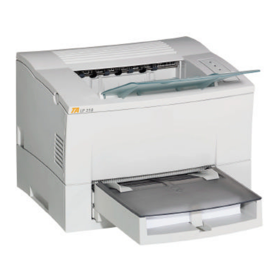
Features Features The various features listed below make the Laser Printer 300 Series the powerful printer for any size office. • Fast 18-page-per-minute print speed for quick output • 1200 600 dpi resolution for superior print quality • PCL 6 emulation for powerful printer language support •... - Page 21 Printer Parts and Accessories Printer Parts and Accessories Printer Control panel Face-down tray Paper guide Power switch Tray 1 (Multipurpose tray) Top cover release button USB interface connector Power cord socket Parallel interface connector...
- Page 22 Printer Parts and Accessories Fusing unit Top cover Paper guide Manual feed tray Image transfer roller Tray cover Imaging cartridge...
- Page 23 Printer Parts and Accessories Options Cassette cover Tray 2 (500-sheet second cassette) Cassette cover Tray 3 (500-sheet Second paper third cassette) Third paper cassette unit cassette unit Duplex unit...
-
Page 24: Indicators
Control Panel Control Panel The control panel has three indicators and one button. Ready (green) indicator Paper (amber) indicator Error (red) indicator Panel button Indicators The three indicators turn on, off, or blink in combination to let you know the current status of the printer. Note You can find out details of the printer’s status by checking the informa- tion that appears on your computer screen (see “Starting Up the Status... -
Page 25: Panel Button
Control Panel Panel Button The panel button can be used to perform various operations according to the status of the printer. • Print configuration page • Form feed For details, see “Using the Panel Button” on page 3-1. -
Page 26: Setting-Up
2Chapter Setting-Up... - Page 27 Setting-Up Chapter 2...
-
Page 28: Selecting A Location For The Printer
Installation Precautions Installation Precautions Note the following important precautions when selecting a location for the printer and when connecting it to a power source. Selecting a Location for the Printer A proper location helps to ensure that your printer provides you with the long service life for which it is designed. -
Page 29: Installation Precautions
Installation Precautions Space Requirements Be sure to provide space around the printer as indicated below, to ensure easier printer operation, paper and toner replacement, and main- tenance. 11-3/4 in. / 30 cm 6 in. / 15 cm 24-3/4 in. / 63 cm 40-1/2 in. -
Page 30: Power Source
Installation Precautions Power Source The following are the power source requirements for this printer. Power supply: 220-240 V at 50–60 Hz Voltage fluctuation: 220-240 V, Frequency fluctuation: Within 3 Hz Note Use a power source with minimal voltage and frequency fluctuation. Only use an outlet that is rated for the voltage capacity specified for this printer. - Page 31 Installation Precautions Grounding Always ground the printer to guard against the danger of electrical shock. To ground the printer, connect the grounding wire to the ground terminal of the electrical outlet you are plugging in to or to a grounding contact that complies with local electrical standards in your area.
-
Page 32: Operating Environment
Operational Precautions Operational Precautions Note the following important precautions whenever using the printer. Operating Environment The following describes the operating environment required when using the printer. Temperature: 10 to 35 C (50 F to 95 F) with fluctuation of 10 C 18 F) per hour Humidity: 15% to 85% with fluctuation of 20% per hour Printer... -
Page 33: Operational Precautions
Operational Precautions • Never place any heavy objects on the power cord, pull on it or bend it. Doing so creates the danger of fire or electrical shock. • Always make sure the printer is not placed on the electrical cord or the communications cables of any other electrical equipment. -
Page 34: Printer Supplies
Operational Precautions Attention Placer l’imprimante dans une pièce largement ventilée Une quantité d’ozone négligable est dégagée pendant le fonctionne- ment de l’imprimante quand celle-ci est utilisée normalement. Cependant, une odeur désagréable pent être ressentie dans les pièces dont l’aération est insuffisante et lorsqu’une utilisation prolongée de l’imprimante est effectuée. -
Page 35: Unpacking The Printer
Installing Installing Unpacking the Printer Take the items and accessories shown below out of the carton. 1. Face-down tray 2. Printer 3. Accessories Installation Guide CD-ROM Power cord 4. Tray 1 Caution After unpacking, keep all packing materials out of the reach of children. - Page 36 Installing Remove the plastic bag and peel off the shipping tape from the printer. Pull out the two cushions from the paper feed inlet. Pull out the plastic-lead strip from the paper feed inlet.
-
Page 37: Installing The Face-Down Tray
Installing Remove the tape strip from the back of the printer. For instructions on installing the optional item(s), see “Options” on page 2-20. Installing the Face-Down Tray With both hands, gently bend the face-down tray inwards and insert one of its tabs into its holder on the upper portion of the printer. Con- tinue to bend the face-down tray so that it curves enough for the sec- ond tab to fit into its holder and release the tray into position. -
Page 38: Installing Tray 1
Installing Installing Tray 1 Using the left and right slots in the printer as guides, gently push Tray 1 until it cannot be inserted any further (as shown in the illustration). Attach the tray cover onto Tray 1. 2-11... -
Page 39: Connecting The Power Cord
Setting-Up Setting-Up Set-up the printer according to the following instructions. Connecting the Power Cord Make sure that the power switch is in the (Off) position. Connect one end of the power cord that comes with the printer to the power cord socket. Plug the other end into a power outlet. 2-12... -
Page 40: Loading Paper
Setting-Up Loading Paper Remove the tray cover from Tray 1. Open all three paper guides. 2-13... - Page 41 Setting-Up Place a stack of paper in the center of Tray 1. Secure the stack by adjusting the paper guides. Replace the tray cover onto Tray 1. 2-14...
-
Page 42: Turning On The Printer
Setting-Up Turning On the Printer After connecting the printer to a power outlet, press the power switch to turn it on. Turning on the printer causes all the indicators on the control panel to light, which indicates that the printer is warming up. In about 23 seconds or less, only the Ready indicator remains lit, indicating that the printer is ready to print. -
Page 43: Testing The Printer
Setting-Up Testing the Printer Perform the following procedure to print a configuration page and see if the printer is working correctly. Note See “No Output” on page 6-17 for information on what to do if the con- figuration page does not print when you press the panel button. Place the Letter size paper onto Tray 1. - Page 44 Setting-Up Sample Configuration Page 2-17...
-
Page 45: Connecting To A Computer
Setting-Up Connecting to a Computer For Parallel Interface Caution Always use a shielded interface cable. Use of an unshielded cable can result in radio interference with data. Note You must purchase an IEEE 1284 type-B cable for connection between the printer and a computer. For detailed specifications of the interface cable, see “Interface Connector and Cable”... -
Page 46: For Usb Interface
Setting-Up For USB Interface Note This printer cannot be connected with a USB cable to a computer run- ning Windows 95 or Windows NT 4.0. Turn on your computer and start up Windows. Turn on the printer. Check that Windows has finished starting up and that the printer is ready. -
Page 47: Second/Third Paper Cassette Unit
Options Options This section describes the optional items that are available for this printer. Second/Third Paper Cassette Unit The second/third paper cassette unit comes equipped with a cassette that can hold up to 500 sheets of Letter size paper called Tray 2/Tray The same unit can accommodate a variety of other paper trays as well (A4, JIS B5, Legal, Executive). - Page 48 Options Space Requirements 30 cm/11- 3/4 in. 75 cm/29- 15 cm/ 1/2 in. 6 in. *87 cm/ 34-1/4 in. 10 cm/4 in. 103 cm/ 40-1/2 in. 60 cm/23- 1/2 in. 30 cm/11-3/4 in. 84 cm/33 in. * when equipped with the third paper cassette unit. 2-21...
- Page 49 Options Installing the Second/Third Paper Cassette Unit Turn off the printer and then disconnect the power cord and interface cable from the printer. Remove the paper cassette unit and the cassette from their packaging, including the protective tape used to hold the various components in place.
- Page 50 Options Place the printer on top of the base unit. Make sure to align the coupling pins of the base unit with the holes located underneath the printer. Second paper cassette unit Third paper cassette unit Note The printer weighs approximately 18 kg (39.7 lbs.) with the optional second paper cassette unit installed.
- Page 51 Options Replace the cassette cover and insert Tray 2 or Tray 3 into the paper cassette unit. Tray 2 Tray 3 2-24...
- Page 52 Options Note Be sure to use both hands whenever the cassette is removed from or inserted into the paper cassette unit. Connect the power cord to the printer and then turn on the printer. See “Connecting the Power Cord” on page 2-12. See “Turning On the Printer”...
-
Page 53: Duplex Unit
Options Duplex Unit Your printer supports double-sided printing if the optional duplex unit is installed. Double-sided documents can be generated for binding along either the short or long edges of the paper through the printer software. For more information, refer to “Duplex Printing” on page 3- •... -
Page 54: Installing The Duplex Unit
Options Installing the Duplex Unit Turn off the printer and then disconnect the power cord and interface cable from the printer. Remove the duplex unit from the packaging including the pro- tective tape used to hold the various components in place. With a screwdriver or similar instrument, remove the flat clip that is attached to the back of the main unit of the printer. - Page 55 Options Align the “L” shaped duplex unit to the back of the main unit of the printer so that the bottom of the “L” is inside of the opening at the bottom of the printer. Note Make sure that the connector of the unit is inserted into the printer securely.
- Page 56 Options With one hand holding the duplex unit in position, use a Phillips screwdriver to tighten the screws that are permanently attached to the back of the duplex unit. Note Hold up the duplex unit with your hand during installation until it is secured to the printer with the screws.
-
Page 57: Expansion Memory
Options Expansion Memory You can avoid many errors caused by data overload by installing suffi- cient memory into the printer. This printer comes with 8 MB of memory. You can increase memory capacity up to 104 MB by installing an optional 8, 16 or 32 MB expan- sion memory (SIMM) into the printer. - Page 58 Options Remove the two screws that hold the side cover of the printer in place with a screwdriver. Clips secure the exterior side cover from the inside of the printer. Gently maneuver the exterior side cover until the clips release (see illustration).
- Page 59 Options Remove the internal side cover to expose the main circuit. Caution Do not touch any part of the main circuit inside the printer. Being careful not to touch the connection points along the edge of the expansion memory, insert the expansion memory into one of the available sockets on the main circuit SIMM sockets 2-32...
- Page 60 Options • Insert the expansion memory at an angle as shown and gently swing it into the socket. • Apply pressure until the expansion memory locks into place. Replace the internal side cover using the four screws. 2-33...
- Page 61 Options Replace the external side cover using the two screws provided to secure it in place. Print a Configuration Page (see page 2-16) and check to confirm that the “Total Memory” item correctly shows the increase in memory capacity. If it does not, repeat the above steps making sure that the expansion memory is installed correctly.
-
Page 62: Using The Printer
3Chapter Using the Printer... - Page 63 Using the Printer Chapter 3...
-
Page 64: Print Configuration Page
Using the Panel Button Using the Panel Button The panel button can be used to perform various operations according to the status of the printer. Panel button Print Configuration Page Use the following procedure whenever you want to configuration for printer. -
Page 65: Type
Printing Paper Printing Paper Type Caution This printer is designed to print on only the following types of paper. Paper Source Manual Tray 2/ Feed Tray 1 Tray 3 Paper Type Tray Plain Paper weight: 60-90 g/m (16 - 24 lbs.) Recycled Paper weight: 60-90 g/m... -
Page 66: Standard Sizes
Printing Paper Size Caution This printer is designed to print on only the following sizes of paper. Standard sizes Paper Source Manual Tray 2/ Feed Tray 1 Tray 3 Paper Size Tray 210 mm 297 mm None 148 mm 210 mm JIS B5 182 mm 257 mm... - Page 67 Printing Paper Envelope and Custom Size Paper Source Manual Tray 2/ Feed Tray 1 Tray 3 Paper Size Tray Env. DL None 110 mm 220 mm Env. C5 None 162 mm 229 mm Env. B5 None 176 mm 250 mm Envelope and Cus- Env.
-
Page 68: Printing Paper
Printing Paper Note Do not use the following types of paper to avoid reduced print quality, a misfeed or print failure. • Paper already used in a thermal transfer printer or ink jet printer. • Paper that is too thin or too thick. •... -
Page 69: Printable Area
Printing Paper Printable Area This printer is designed to print on paper with a 4 mm (0.16 in.) margin on all sides. 4 mm 4 mm (0.16 in.) (0.16 in.) 4 mm (0.16 in.) Printable area 4 mm (0.16 in.) - Page 70 Loading Paper Loading Paper The following sources can be used to feed paper into the printer: • Tray 1 • Manual feed tray • Tray 2/Tray 3 (option) Tray 1 is the standard source for supplying paper to the printer. Various types and sizes of paper can be fed from this tray.
-
Page 71: Loading Paper Onto Tray 1
Loading Paper Loading Paper onto Tray 1 You can load up to 250 sheets of standard paper onto Tray 1. See “Printing Paper” on page 3-2 for details on paper sizes and types. Remove the tray cover from Tray 1. Open the paper guides. - Page 72 Loading Paper Place a stack of paper in the center of Tray 1. Adjust the paper guides so that both the left and the right sides of the paper stack are secure. Maximum level mark Note A maximum level mark on the paper guide shows how high you can stack paper on Tray 1.
- Page 73 Loading Paper Manual Loading (Manual Feed Tray) Make sure that the tray cover is properly attached to Tray 1. Open the paper guides. Insert the sheet of paper into the manual feed tray with the side to be printed facing up. Note Insert only one sheet of paper at a time when feeding manually.
-
Page 74: Printing On Envelopes
Loading Paper Adjust the paper guides so that both sides of the paper are secure. Printing on Envelopes The manual feed tray supports Commercial 10, Monarch, DL, C5, and B5 envelopes. Note Because there is great variation in the quality of paper used for enve- lopes, we suggest that you produce test prints of various types before purchasing any envelope in large quantities for use with this printer. - Page 75 Loading Paper Place the envelope with the side to be printed facing up on the tray. The flap of the envelope should be facing down and to the left. Note Insert only one envelope at a time when feeding manually. Make sure that the envelope is placed in the center of the tray and that it is secured by the paper guides.
- Page 76 Loading Paper Loading Paper onto Tray 2/Tray 3 (Option) You can load up to 500 sheets of standard paper onto Tray 2/Tray 3. See “Printing Paper” on page 3-2 for details on paper sizes and types. Note Make sure that the Tray 2/Tray 3 for the proper size of paper to be used for printing has been installed into the second/third paper cassette unit.
- Page 77 Loading Paper Remove the cassette cover from Tray 2/Tray 3. Press down on the paper lifting plate located inside of Tray 2/ Tray 3 until it locks. 3-14...
- Page 78 Loading Paper Place a stack of up to 500 sheets of paper into Tray 2/Tray 3 so that the side that was facing up when the paper was unwrapped is still facing up. Note A maximum level mark inside the inlet of Tray 2/Tray 3 shows how high you can stack paper on Tray 2/Tray 3.
- Page 79 Loading Paper Replace the cassette cover and insert Tray 2/Tray 3 into the second/third paper cassette unit. Tray 2 Tray 3 3-16...
-
Page 80: Duplex Printing
Duplex Printing Duplex Printing This feature prints document data on both sides of a sheet of paper. Installation of the optional duplex unit is required to perform duplex printing. You can choose either Bind Long Edge or Bind Short Edge when gen- erating duplex documents. -
Page 81: Paper Type
Duplex Printing The supported paper types and sizes for duplex printing are as follows. Paper Type Plain paper: 60-90 g/m (16 - 24 lbs.) Recycle paper: 60-90 g/m (16 - 24 lbs.) Note Do not use special paper (transparencies, labels, envelopes, letterhead and thick paper) for duplex printing. -
Page 82: Pcl Printer Driver
4Chapter PCL Printer Driver... - Page 83 PCL Printer Driver Chapter 4...
-
Page 84: Introduction
Introduction Introduction The Laser Printer 300 Series PCL Printer Driver was specially devel- oped to provide true Windows-based printing for users. The Laser Printer 300 Series PCL Printer Driver consists of three programs: the Laser Printer 300 Series PCL Printer Driver, the Printer Status Display and the Control Panel. -
Page 85: System Requirements
System Requirements System Requirements The following describes the minimum system requirements that are necessary to correctly run the Laser Printer 300 Series PCL Printer Driver. Operating System: Microsoft Windows 95, Windows 98, Windows Me, Windows NT 4.0 or Windows 2000 Personal Computer: IBM-compatible PC with at least a 486DX 16MHz CPU (Pentium processor recommended) CD-ROM drive... -
Page 86: Installing The Usb Device Driver For The Laser Printer 300 Series
Installing the USB Device Driver for the Laser Printer 300 Series Installing the USB Device Driver for the Laser Printer 300 Series When connecting the Laser Printer 300 Series printer to your computer with a USB cable, install the USB device driver according to the fol- lowing instructions before installing the printer driver. - Page 87 Installing the USB Device Driver for the Laser Printer 300 Series Connect the printer to the computer with the USB cable (For more details, refer to “Connecting to a Computer” on page 2- 18.) to display the Add New Hardware Wizard dialog.
- Page 88 Installing the USB Device Driver for the Laser Printer 300 Series When the following dialog appears, click to finish the Finish installation. This completes the installation of the USB device driver for the Laser Printer 300 Series printer. When the Add Printer Wizard dialog appears, continue with the procedure in “To Install the PCL Printer Driver Using the Add Printer Wizard”...
-
Page 89: To Install The Usb Device Driver Under Windows Me
Installing the USB Device Driver for the Laser Printer 300 Series To Install the USB Device Driver Under Windows Me Turn on your computer and start up Windows Me. Turn on the printer. Check that Windows Me has finished starting up and that the printer is ready. - Page 90 Installing the USB Device Driver for the Laser Printer 300 Series Check the Search for the best driver for your device. (Rec- option button, check the box, ommended) Specify a location and then click Browse Browse the CD-ROM and navigate to: .
- Page 91 Installing the USB Device Driver for the Laser Printer 300 Series When the following dialog appears, click to finish the Finish installation. This completes the installation of the USB device driver for the Laser Printer 300 Series. When the Add Printer Wizard dialog appears, continue with the procedure in “To Install the PCL Printer Driver Using the Add Printer Wizard”...
-
Page 92: To Install The Usb Device Driver Under Windows 2000
Installing the USB Device Driver for the Laser Printer 300 Series To Install the USB Device Driver Under Windows 2000 If the printer is connected to the computer using a USB cable, USB Printing Support may automatically be incorporated, depending on the operating system. - Page 93 Installing the USB Device Driver for the Laser Printer 300 Series Connect the printer to the computer with the USB cable (For more details, refer to “Connecting to a Computer” on page 2- 18.) to display the Found New Hardware Wizard dialog. Using the Found New Hardware Wizard, install the Laser Printer 300 Series PCL Printer Driver.
- Page 94 Installing the USB Device Driver for the Laser Printer 300 Series Click the tab of the USB Printing Support Properties dia- Driver log, and then click Update Driver 4-11...
- Page 95 Installing the USB Device Driver for the Laser Printer 300 Series Click to display the next dialog. Next Check the Search a suitable driver for my device (recom- mended) option button, and then click Next When the next dialog appears, check the Specify a location box, and then click Next...
- Page 96 Installing the USB Device Driver for the Laser Printer 300 Series When the following dialog appears, click Cancel Note Be sure to click to stop the Add Printer Wizard. Cancel 4-13...
- Page 97 Installing the USB Device Driver for the Laser Printer 300 Series When the following dialog appears, click to finish install- Finish ing the USB device driver. Continue with this procedure to set the printer port. Click , point to , and then click to display Start Settings...
- Page 98 Installing the USB Device Driver for the Laser Printer 300 Series Select from the menu. Properties File In the Properties dialog, click the Ports tab, and then select from the ports list. USB/001 Laser Printer 300 Series 4-15...
- Page 99 Installing the USB Device Driver for the Laser Printer 300 Series Note Remove the check for the port with “Virtual printer port for USB” listed under Description , and then select the port with “Laser Printer 300 Series” listed under Description Click Apply...
-
Page 100: Installing The Pcl Printer Driver Under Windows 95
Installing the PCL Printer Driver Under Windows 95 Installing the PCL Printer Driver Under Windows 95 This section provides information on installing the Laser Printer 300 Series PCL Printer Driver under Windows 95. To Install the PCL Printer Driver Using Plug- and-Play After connecting the printer to your computer with the parallel cable, turn on the printer. - Page 101 Installing the PCL Printer Driver Under Windows 95 Follow the instructions that appear on your computer screen to complete the installation. Note An opportunity to designate a name for the printer will be pro- vided during the installation procedure. Check that the printer icon is Laser Printer 300 Series PCL6 displayed in the Printers dialog.
-
Page 102: To Install The Pcl Printer Driver Using The Add Printer Wizard
Installing the PCL Printer Driver Under Windows 95 To Install the PCL Printer Driver Using the Add Printer Wizard Turn on your computer and start up Windows 95. Insert the CD-ROM that comes with your printer Printer Driver into your computer’s CD-ROM drive. Click , point to , and then click... - Page 103 Installing the PCL Printer Driver Under Windows 95 Check that the printer icon is Laser Printer 300 Series PCL6 displayed in the Printers dialog. Eject the CD-ROM from your computer’s CD-ROM drive. This completes the installation of printer driver. 4-20...
-
Page 104: Installing The Pcl Printer Driver Under Windows 98/Windows Me
Installing the PCL Printer Driver Under Windows 98/ Windows Me Installing the PCL Printer Driver Under Windows 98/Windows Me This section provides information on installing the Laser Printer 300 Series PCL Printer Driver under Windows 98 or Windows Me. To Install the PCL Printer Driver Using Plug- and-Play Under Windows 98 The Plug-and-Play installation with a parallel connection is described below. - Page 105 Installing the PCL Printer Driver Under Windows 98/ Windows Me Check the box, and then click Specify a location: Browse Browse the CD-ROM and navigate to: Printer Driver . Next, click English\PCL6Driver\W98Nt2K Click Next Follow the instructions that appear on your computer screen to complete the installation.
-
Page 106: To Install The Pcl Printer Driver Using Plug-And-Play Under Windows Me
Installing the PCL Printer Driver Under Windows 98/ Windows Me To Install the PCL Printer Driver Using Plug- and-Play Under Windows Me The Plug-and-Play installation with a parallel connection is described below. For details on the installation with a USB connection, see “To Install the USB Device Driver Under Windows Me”... - Page 107 Installing the PCL Printer Driver Under Windows 98/ Windows Me Follow the instructions that appear on your computer screen to complete the installation. Note An opportunity to designate a name for the printer will be pro- vided during the installation procedure. Check that the printer icon is Laser Printer 300 Series PCL6...
-
Page 108: To Install The Pcl Printer Driver Using The Add Printer Wizard
Installing the PCL Printer Driver Under Windows 98/ Windows Me To Install the PCL Printer Driver Using the Add Printer Wizard Turn on your computer and start up Windows 98 or Windows Insert the CD-ROM that comes with your printer Printer Driver into your computer’s CD-ROM drive. - Page 109 Installing the PCL Printer Driver Under Windows 98/ Windows Me Click Next Click , and then click Have Disk Browse Browse the CD-ROM and navigate to: Printer Driver . Next, click English\PCL6Driver\W98Nt2K Click , and then click Next If you selected in step 6, specify the desired port.
-
Page 110: Installing The Pcl Printer Driver Under Windows Nt 4.0
Installing the PCL Printer Driver Under Windows NT 4.0 Installing the PCL Printer Driver Under Windows NT 4.0 This section provides information on installing the Laser Printer 300 Series PCL printer driver on a computer running Windows NT 4.0. To Install the PCL Printer Driver Using the Add Printer Wizard Turn on your computer and start up Windows NT 4.0. - Page 111 Installing the PCL Printer Driver Under Windows NT 4.0 Select My Computer Click Next Specify the ports you want to use and the click Next Click Have Disk , and then click Browse Browse the Printer Driver CD-ROM and navigate to: .
- Page 112 Installing the PCL Printer Driver Under Windows NT 4.0 Check that the printer icon is Laser Printer 300 Series PCL6 displayed in the Printers dialog. Eject the CD-ROM from your computer’s CD-ROM drive. This completes the installation of printer driver. 4-29...
-
Page 113: Installing The Pcl Printer Driver Under Windows 2000
Installing the PCL Printer Driver Under Windows 2000 Installing the PCL Printer Driver Under Windows 2000 This section provides information on installing the Laser Printer 300 Series PCL printer driver on a computer running Windows 2000. To Install the PCL Printer Driver Using Plug- and-Play For a parallel connection: After connecting the printer to your computer, turn on the... - Page 114 Installing the PCL Printer Driver Under Windows 2000 For a USB connection: Turn on your computer and start up Windows 2000. Turn on the printer. Check that Windows 2000 has finished starting up and that the printer is ready. Connect the printer to the computer with the USB cable (For more details, refer to “Connecting to a Computer”...
- Page 115 Installing the PCL Printer Driver Under Windows 2000 Browse the CD-ROM and navigate to: Printer Driver . Next, click English\PCL6Driver\W98Nt2K Open Click , and then click Next Follow the instructions that appear on your computer screen to complete the installation. Check that the printer icon is Laser Printer 300 Series PCL6...
-
Page 116: To Install The Pcl Printer Driver Using The Add Printer Wizard
Installing the PCL Printer Driver Under Windows 2000 To Install the PCL Printer Driver Using the Add Printer Wizard Turn on your computer and start up Windows 2000. Insert the CD-ROM that comes with your printer Printer Driver into your computer’s CD-ROM drive. Click , point to , and then click... - Page 117 Installing the PCL Printer Driver Under Windows 2000 Select Local printer Note is selected, do not check the Local Printer Automatically box. detect and install my plug and play printer 4-34...
- Page 118 Installing the PCL Printer Driver Under Windows 2000 Click Next Click the button, and specify the ports Use the following port: you want to use and the click Next • If a parallel connection is being used, select LPTX: (X=1, 2, etc.).
-
Page 119: Installing The Laser Printer 300 Series Utilities4
Installing the Laser Printer 300 Series Utilities Installing the Laser Printer 300 Series Utilities This section provides information on installing the Laser Printer 300 Series Utilities. Insert the Printer Driver CD-ROM that comes with your printer into your computer’s CD-ROM drive. Double-click the My Computer icon on the desktop, and then... - Page 120 Installing the Laser Printer 300 Series Utilities In the following dialog that appears, you can select whether or not the Status Display starts up automatically when Windows is started. To start up Status Display automatically, check the box. Setup to Start Status Display automatically After the installation is completed, the following dialog appears on the desktop of the computer.
-
Page 121: Using The Pcl Printer Driver
Using the PCL Printer Driver Using the PCL Printer Driver The printer driver provides you with control over a wide variety of printer parameters from your computer. The following sections provide an overview of the seven tabs of the printer driver’s Properties dialog box. - Page 122 Using the PCL Printer Driver On the tab of the Properties dia- –> 32-bit SuperDriver Setup log, the following window appears. 4-39...
- Page 123 Using the PCL Printer Driver To Display the PCL Printer Driver Setup Dialog Under Windows NT 4.0/Windows 2000 Click Start , point to Settings , and then click Printers to display the Printers dialog. In the Printers dialog, click the Laser Printer 300 Series PLC6 printer icon.
- Page 124 Using the PCL Printer Driver For Windows NT 4.0, select from the Document Defaults… menu. For Windows 2000, select File Printing Preference… from the File menu. Windows 2000 Windows NT 4.0 The following window appears. 4-41...
-
Page 125: Common Buttons
Using the PCL Printer Driver Common Buttons The buttons described below appear at the bottom of each tab. Click to exit the Properties dialog box, saving any changes made. Cancel Click to exit the Properties dialog box without saving any changes made. -
Page 126: Setup
Using the PCL Printer Driver Setup tab contains settings concerning the paper source, a realtime Setup graphic mirror of most driver settings as well as the following features. N-up settings allow you to print multiple documents on a single N-up page. - Page 127 Using the PCL Printer Driver You can place a border between N-up documents by checking the Bor- box. der Line N-up Window Click on the N-up Style... to open a dialog that will allow you to spec- ify the order in which N-up documents are placed on the page. There are four patterns to choose from: horizontal ascending, horizontal descending, vertical ascending and vertical descending.
- Page 128 Using the PCL Printer Driver Watermark Watermarks are placed on a document to quickly alert the reader to the nature of its content. For example: CONFIDENTIAL, DRAFT, etc. Through the driver, you can specify several guidelines that effect the style, content and placement of watermarks. drop-down list catalogs the menu of watermarks that Watermark have been entered into the printer’s memory.
- Page 129 Using the PCL Printer Driver To Remove a Watermark from the List Select the watermark that you wish to remove from the list, click the Delete button and click To Add a Watermark Click the button to open the Watermark Edit dialog. Name The name that you wish to use to identify the watermark in the Watermark list is entered here.
- Page 130 Using the PCL Printer Driver Angle Select the angle of the watermark from the drop-down list. User Setting If User Setting was selected from the drop- down list, specify the angle of the watermark here. Position Center: Check here to position the watermark in the center of the document.
- Page 131 Using the PCL Printer Driver Duplex/Booklet feature enables your printer to support double-sided print- Duplex ing. The following orientation options for duplex printing are available from the drop-down list. Allows you to print portrait-oriented documents Short Edge Binding: in a calendar-style format. Allows you to print portrait-oriented documents Long Edge Binding: in a book-style format.
-
Page 132: Paper Source
Using the PCL Printer Driver Note Booklet feature of the printer driver cannot be used when printing documents (see page 4-44). settings cannot be enabled at the Fit to Paper Scaling Booklet same time (see page 4-53). Paper Source The Paper Source item specifies the tray from which paper is fed from the printer. - Page 133 Using the PCL Printer Driver Detail of Paper Source If the first page is to be supplied from a tray different from the tray sup- plying paper for the rest of the document, click this button. The Detail of Paper Source dialog appears. Check the Front Cover Page box, and then select the desired paper...
-
Page 134: Paper
Using the PCL Printer Driver Paper tab contains functions that effect the format and output of Paper your printed documents. Original Document Size The various sizes of paper that are supported by your printer are dis- played in the drop-down list. Select the appropriate size or add a cus- tom size (see Edit Custom…). -
Page 135: Edit Custom
Using the PCL Printer Driver Envelopes Env. Com-10 4-1/8 9-1/2 in. Env. Monarch 3-7/8 7-1/2 in. Env. C5 229 mm Env. DL 220 mm Env. B5 250 mm Edit Custom... Click this button to display the Custom Paper dialog box for defining the dimensions of custom paper sizes you want to add to the Paper list, and for editing existing custom paper sizes. -
Page 136: Output Paper Size
Using the PCL Printer Driver To delete a custom paper size from the list, select the desired paper name, and then click Delete Enter the name of the custom size into the field. Next, enter the Name dimensions for width and height into the appropriate boxes. Be sure to specify either inches or centimeters and click . - Page 137 Using the PCL Printer Driver Note Scaling of the printer driver cannot be used when printing N-up doc- uments (see page 4-44). settings cannot be enabled at the same time Scaling Booklet (see page 4-48). Copies This item specifies the number of copies to be printed. You can specify any value from Collate The Collate feature supports multi-document printing (when the num-...
-
Page 138: Quality
Using the PCL Printer Driver Quality tab allows you to make setting changes that enhance the Quality graphic quality of your printed documents. Resolution This setting specifies the number of dots per inch (dpi). 600dpi: Use this setting for normal resolution printing. Use this setting for high-resolution printing. - Page 139 Using the PCL Printer Driver Halftoning Halftoning can be used to improve the texture of graphics. Changing the Halftoning will affect the gray tones and shadows of an image. The Standard is recommended for all documents. This Standard: option provides fast printing. Documents that have been generated in the Standard may Photocopy: appear too dark when faxed or copied.
-
Page 140: Toner Save
Using the PCL Printer Driver Toner Save This option helps to reduce your printing costs by conserving toner when printing rough drafts or sample documents. Normal amounts of toner are consumed during printing. Off: Documents are printed using minimal amounts of toner. Lighter images and text may be noticed. -
Page 141: Device Options Setting
Using the PCL Printer Driver Device Options Setting The auxiliary accessories that are available for installation appear in this tab. To add an available option from the Installable Options list to the list, select the option and click the button. Installed Options Installed Options list catalogs the optional accessories that have... -
Page 142: Using The Status Display
Using the Status Display Using the Status Display The status display displays information about the current status of the computer’s local printer. Starting Up the Status Display This section describes how to start up the Status Display, which keeps you informed of the status of the printer at all times. Important! Before starting up the Status Display, make sure that the printer is con- nected to your computer and turned on. - Page 143 Using the Status Display To Start Up the Status Display Click the button, point to , then to Start Programs Laser Printer , and then click 300 Series Utilities Laser Printer 300 Series Sta- tus Display Note The screen images that appear in this section show the status display operating in a Windows 98-based environment.
-
Page 144: Using The Status Display
Using the Status Display Using the Status Display Printer Status This area displays text messages that describe the current operational status of the printer. How to recover This area provides you with explanations of what you need to do in order to correct problems and recover from error conditions. -
Page 145: Switching Between The Expanded And Reduced Views
Using the Status Display Switching Between the Expanded and Reduced Views You can use the following procedure to switch between the expanded and reduced views of the Printer Status Display. On the menu, click to reduce the size of the display, Display Reduce to expand it. -
Page 146: Using The Control Panel
Using the Control Panel Using the Control Panel This program displays the current settings of the computer’s local printer. You can also use Control Panel to change settings and to reset counters. Starting Up the Control Panel This section describes how to start up the Control Panel, which you can check and change the current settings of the printer. - Page 147 Using the Control Panel Click the button, point to , then to Start Programs Laser Printer and then click 300 Series Utilities Laser Printer 300 Series Con- trol Panel Note The screen images that appear in this section show the control panel operating in a Windows 98-based environment.
-
Page 148: Using The Control Panel
Using the Control Panel Using the Control Panel The Control Panel has 5 tabs, which you can use to control the follow- ing items. See online help for full details about using these tabs to make settings. Note The following information is common to Windows 95, Windows 98, Windows Me, Windows NT 4.0 and Windows 2000. - Page 149 Using the Control Panel Paper Paper Time Out During manual feeding of paper, the printer pauses during printing to wait for you to feed the next sheet. The “paper timer out” condition exists when the printer is paused and nothing happens for about 10 minutes.
-
Page 150: Printer Setting
Using the Control Panel Printer Setting Power Save These controls determine the power saving settings of your printer. Select the setting to enable the power saving mode. The mode will be disabled if you check . The setting deter- Power Save Interval mines the number of minutes that the printer will sit without receiving a command before entering the power save mode. - Page 151 Using the Control Panel Pre-Heat Select the setting to prewarm the printer’s fusing unit as soon as a print job is received from the host computer. The fusing unit will not warm up immediately after receiving a print job when is selected.
-
Page 152: Test Print
Using the Control Panel Test Print Demo Page Print Click this button to print a Demo Page. Configuration Print Click this button to print a page that shows the printer’s current config- uration. Print the List of PCL Resident Fonts Click this button to print a list of the PCL resident fonts that are installed on your printer. - Page 153 Using the Control Panel Counter Total Counter This value shows how many pages have been printed throughout the life of the printer. This value cannot be reset. Tray2 Counter This value shows how many pages have been printed from Tray 2. This value can be reset to zero by clicking the Reset button.
- Page 154 Using the Control Panel Configuration Printer Name This box shows the name assigned to the printer. Total Memory This box shows how much memory is installed on the printer. Additional Accessories This box shows any additional accessories installed on the printer. 4-71...
-
Page 155: Uninstalling The Pcl Printer Driver
Uninstalling the PCL Printer Driver Uninstalling the PCL Printer Driver This section describes how to uninstall the Laser Printer 300 Series Printer Driver when necessary. To Uninstall the PCL Printer Driver Note The screen images that appear in this section show the examples of unin- stallation under a Windows 98-based environment. - Page 156 Uninstalling the PCL Printer Driver For Windows 95, Windows 98, Windows Me or Windows NT 4.0, select , and then click Laser Printer 300 Series PCL6 Add/ Remove to uninstall the printer driver. 4-73...
- Page 157 Uninstalling the PCL Printer Driver For Windows 2000, select , and then Laser Printer 300 Series PCL6 click to uninstall the printer driver. Change/Remove Select Laser Printer 300 Series PCL6 in the Uninstall dialog. 4-74...
- Page 158 Uninstalling the PCL Printer Driver Click to proceed with the uninstallation or Uninstall Cancel abort. When the following dialog appears, click to restart the com- puter. Note It is recommended that you restart your computer after uninstalla- tion. If the Laser Printer 300 Series Utilities has been installed, also unin- stall it.
-
Page 159: Uninstalling The Laser Printer 300 Series Utilities
Uninstalling the Laser Printer 300 Series Utilities Uninstalling the Laser Printer 300 Series Utilities This section describes how to uninstall the Laser Printer 300 Series Utilities when necessary. To Uninstall the Laser Printer 300 Series Utilities Note The screen images that appear in this section show the examples of unin- stallation under a Windows 98-based environment. - Page 160 Uninstalling the Laser Printer 300 Series Utilities For Windows 95, Windows 98, Windows Me or Windows NT 4.0, select , and then click Laser Printer 300 Series Utilities Add/Remove to uninstall the utilities. 4-77...
- Page 161 Uninstalling the Laser Printer 300 Series Utilities For Windows 2000, select Laser Printer 300 Series Utilities and then click to uninstall the utilities. Change/Remove Click to begin the uninstallation. 4-78...
- Page 162 Uninstalling the Laser Printer 300 Series Utilities Click the appropriate button, and then continue the uninstalla- tion. When the following dialog appears, click to finish the unin- stallation. 4-79...
-
Page 163: Uninstalling The Usb Device Driver
Uninstalling the USB Device Driver Uninstalling the USB Device Driver This section descries how to uninstall the USB device driver when nec- essary. To Uninstall the USB Device Driver Click the button, point to , and then click Start Settings Control Panel Double-click the... - Page 164 Uninstalling the USB Device Driver For Windows 2000, select Laser Printer 300 Series USB , and then click to uninstall the USB Driver Change/Remove device driver. 4-81...
- Page 165 Uninstalling the USB Device Driver 4-82...
-
Page 166: Maintenance
5Chapter Maintenance... - Page 167 Maintenance Chapter 5...
-
Page 168: Replacing The Imaging Cartridge
Replacing the Imaging Cartridge Replacing the Imaging Cartridge The imaging cartridge contains the print drum and enough toner to produce about 9,000 A4/Letter-size prints. The imaging cartridge that comes with the printer is capable of producing approximately 5,000 A4/Letter-size prints. This is calculated based on an average image density equivalent to a black-to-white ratio of 5% or less. -
Page 169: To Replace The Imaging Cartridge
Replacing the Imaging Cartridge To Replace the Imaging Cartridge Turn off the printer and disconnect the power cord and interface cable from the printer. Close the face-down tray and press the top cover release but- ton to open the top cover. Note Be sure to close the face-down tray before opening the top cover to prevent injuries. - Page 170 Replacing the Imaging Cartridge ATTENTION The fusing unit inside the printer can become very hot during operation. Do not touch the area to avoid injury. Fusing unit...
- Page 171 Replacing the Imaging Cartridge Remove the old imaging cartridge. Note Do not touch the shutter of the imaging cartridge to avoid caus- ing damage to the drum unit. When handling the imaging car- tridge, always use the handle. Take a new imaging cartridge out of the box. Holding it firmly with both hands, shake it 4 or 5 times in the directions indicated by the arrows in the illustration to distribute the toner evenly.
- Page 172 Replacing the Imaging Cartridge Align the green labels on the imaging cartridge with the green labels that have been affixed to the cartridge guides inside of the printer. Install the imaging cartridge by sliding both pins (1) of the imaging cartridge along the grooves of the printer’s internal cartridge guides.
- Page 173 Replacing the Imaging Cartridge Note When installing the imaging cartridge, hold the handle so it is angled as shown in the illustration.
- Page 174 Replacing the Imaging Cartridge The cartridge will click into place when it is completely installed. Close the top cover and press it down gently but firmly until it locks into place.
-
Page 175: Cleaning The Outside Of The Printer
Cleaning the Printer Cleaning the Printer Dust, dirt, and paper debris on the outer surfaces and inside the printer can interfere with printer performance. Clean the printer regularly. ATTENTION The fusing unit inside the printer can become very hot during opera- tion. -
Page 176: Cleaning The Paper Feed Roller
Cleaning the Printer Cleaning the Paper Feed Roller Turn off the printer and unplug the power cord. Close the face-down tray and press the top cover release but- ton to open the top cover. Note Be sure to close the face-down tray before opening the top cover to prevent injuries. - Page 177 Cleaning the Printer Remove the imaging cartridge. Caution Whenever you remove the imaging cartridge from the printer, immediately wrap it with a cloth to protect it against overex- posure to light. 5-10...
- Page 178 Cleaning the Printer Pull back on the cover that protects the paper feed roller located at the bottom of the printer chamber. Use a soft cloth to wipe the paper feed roller. 5-11...
- Page 179 Cleaning the Printer Reinstall the imaging cartridge. See “Replacing the Imaging Cartridge” on page 5-1 for details. Close the top cover and press it down gently but firmly until it locks into place. 5-12...
-
Page 180: Troubleshooting
6Chapter Troubleshooting... - Page 181 Troubleshooting Chapter 6...
-
Page 182: Clearing A Paper Misfeed
Clearing a Paper Misfeed Clearing a Paper Misfeed Use the following procedure to remove the misfed paper inside the printer. Inside the Printer Close the face-down tray and press the top cover release but- ton to open the top cover. Note Be sure to close the face-down tray before opening the top cover to prevent injuries. - Page 183 Clearing a Paper Misfeed ATTENTION The fusing unit inside the printer can become very hot during operation. Do not touch the area to avoid injury. Fusing unit...
- Page 184 Clearing a Paper Misfeed Remove the imaging cartridge. Caution Whenever you remove the imaging cartridge from the printer, immediately wrap it with a cloth to protect it against overex- posure to light. Clear the paper misfeed using one of the following procedures depending upon the location of the paper misfeed.
- Page 185 Clearing a Paper Misfeed In the Vicinity of the Imaging Cartridge • Pull the end of the paper that is visible straight out of the printer. At the Fusing Unit • Pull the end of the paper that is visible straight out of the printer...
- Page 186 Clearing a Paper Misfeed Reinstall the imaging cartridge. See “Replacing the Imaging Cartridge” on page 5-1 for details. Close the top cover and press it down gently but firmly until it locks into place.
-
Page 187: Face-Down Tray
Clearing a Paper Misfeed Face-Down Tray Pull the misfed paper straight out of the printer. After removing a misfed page, be sure to open the top cover then close it again to reset the printer. Tray 1 Remove the tray cover and pull the misfed paper straight out of the printer. - Page 188 Clearing a Paper Misfeed After removing a misfed page, be sure to open the top cover then close it again to reset the printer.
-
Page 189: Manual Feed Tray
Clearing a Paper Misfeed Manual Feed Tray Pull the misfed paper straight out of the printer. After removing a misfed page, be sure to open the top cover then close it again to reset the printer. -
Page 190: Second/Third Paper Cassette Unit (Option)
Clearing a Paper Misfeed Second/Third Paper Cassette Unit (Option) Remove the cassette cover and pull out Tray 2/Tray 3 from the second/third paper cassette unit. Press down on the stack of paper until the paper lifting plate locks. Tray 2 Tray 3 Remove the stack of paper from the tray and pull the misfed paper straight out of the printer. -
Page 191: Duplex Unit (Option)
Clearing a Paper Misfeed Duplex Unit (Option) Upper Misfeed Open the duplex upper cover and pull out the misfed paper. Duplex upper cover After removing a misfed page, be sure to open the top cover then close it again to reset the printer. 6-10... -
Page 192: Lower Misfeed
Clearing a Paper Misfeed Lower Misfeed Open the duplex lower cover and pull out the misfed paper. Duplex lower cover After removing a misfed page, be sure to open the top cover then close it again to reset the printer. 6-11... -
Page 193: Print Quality Problems
Print Quality Problems Print Quality Problems The following provides information on most print quality problems you might encounter. If the advice provided here does not solve your problem, contact customer support. Symptom Cause Remedy Blank pages The imaging Remove the imaging car- cartridge may tridge and rock it left and be running out... - Page 194 Print Quality Problems Symptom Cause Remedy Printout too light The Toner Save Change the setting and try setting of the printing again. printer driver is set to “On”. The imaging Remove the imaging car- cartridge may tridge and rock it left and be running out right a few times to distribute of toner.
- Page 195 Print Quality Problems Symptom Cause Remedy Blurred back- The imaging Remove the imaging car- ground cartridge may tridge and check it for dam- be defective. age. Replace the imaging car- tridge if necessary. See “Replacing the Imaging Car- tridge” on page 5-1 for details.
- Page 196 Print Quality Problems Symptom Cause Remedy Irregularities The paper may Since toner will not adhere have absorbed well to wet paper, replace the some moisture paper you are using with dry due to high paper and try printing again. humidity or because of direct contact with water.
- Page 197 Print Quality Problems Symptom Cause Remedy Toner smudges The toner may Remove the imaging car- be unevenly dis- tridge and rock it left and tributed inside right a few times to distribute the imaging car- remaining toner. tridge. If the problem persists, replace the imaging car- tridge.
-
Page 198: No Output
Print Quality Problems No Output Symptom Cause Remedy Failure to pro- There is a com- Check printer cable type duce output munications against the specifications in problem “Interface Connector and between the Cable” on page 7-7. printer and your computer. Note When checking the cable type, make sure that the... - Page 199 Print Quality Problems Symptom Cause Remedy Check computer’s communi- cation ports settings. Refer to the documentation that comes with your com- puter and check if its current communications port settings are correct. Note If the printer is connected to the computer through a USB connection, refer to “USB Connection Prob- lems”...
-
Page 200: Usb Connection Problems
USB Connection Problems USB Connection Problems In order for the Laser Printer 300 Series printer to operate correctly when connected to the computer’s USB port, a specific computer envi- ronment and certain settings must be used; otherwise, one of the fol- lowing problems may occur. -
Page 201: Was The Computer Correctly Set Up
USB Connection Problems With Windows 2000, check the computer according to the following procedure. Right-click the icon on the desktop, and then My Computer click Properties in the shortcut menu that appears. The System Properties dialog appears. Click the Hardware tab of the System Properties dialog, and then click the button. - Page 202 USB Connection Problems CHECK 1: To check that the printer driver is installed correctly Check that the Laser Printer 300 Series PCL6 printer icon is displayed in the Printers dialog. To display the Printers dialog, click Start , point to Settings , and then click Printers...
- Page 203 USB Connection Problems Check the settings of the printer port. For Windows 98 or Windows Me, select the Laser Printer 300 Series PCL6 printer icon in the Printers dialog, click Properties in the menu, and then click the tab in the Properties File Details dialog.
- Page 204 USB Connection Problems For Windows 2000, select the Laser Printer 300 Series PCL6 printer icon in the Printers dialog, click in the Properties File menu, and then click the Ports tab in the Properties dialog. • If appears in the port list USB/001 Laser Printer 300 Series and is checked, the printer driver is correctly installed.
- Page 205 USB Connection Problems CHECK 2: To check that the USB device driver is installed correctly Turn on the printer, and then connect the printer to the computer with the USB cable. Right-click the icon on the desktop, and then My Computer click in the shortcut menu that appears.
- Page 206 USB Connection Problems • If does not appear below Laser Printer 300 Series Univer- , the USB device driver is not sal serial bus controller installed correctly. (For more details, refer to “Installing the USB Device Driver for the Laser Printer 300 Series” on page 4-3.) With Windows 2000, follow the procedure below.
- Page 207 USB Connection Problems CHECK 3: The installation may have been stopped without finishing. To reinstall both the printer driver and the USB device driver With Windows 98 or Windows Me, follow the procedure below. Uninstall the printer driver. • First, click the Start button, point to Settings...
- Page 208 USB Connection Problems Uninstall the USB device driver. Click the button, point to , and then click Start Settings Control Panel Double-click the icon in the Control Add/Remove Programs Panel dialog to open the Add/Remove Programs Properties dia- log. Select , and then click MLaser Printer 300 Series USB Driver to uninstall the USB device driver.
- Page 209 USB Connection Problems With Windows 2000, follow the procedure below. Uninstall the printer driver. • First, click the Start button, point to Settings , and then click Control Panel • Double-click the icon in the Con- Add/Remove Programs trol Panel dialog to open the Add/Remove Programs Proper- ties dialog.
- Page 210 USB Connection Problems • Select , and then click Laser Printer 300 Series USB Driver to uninstall the printer driver. Change/Remove Install the USB device driver. For more details, refer to “To Install the USB Device Driver Under Windows 2000” on page 4-9.
-
Page 211: Indicator Lights (Printer Messages)
Indicator Lights (Printer Messages) Indicator Lights (Printer Messages) The three indicator lights on the printer’s control panel turn on, turn off, or blink in fixed patterns to let you know the current status of the printer. Refer to the following sections for descriptions of each indica- tor light pattern and the action you need to take when it occurs. - Page 212 Indicator Lights (Printer Messages) Note You can find out details of the printer’s status by checking the informa- tion that appears on your computer screen (see “Starting Up the Status Display” on page 4-59). Standard Status Patterns Indicators Description Indicators Description Power is off.
- Page 213 Indicator Lights (Printer Messages) Indicators Description Indicators Description (Slow blinking) Power save Mode. 6-32...
- Page 214 Indicator Lights (Printer Messages) Operator Call Patterns Indicators Description Action Top cover is open. Close the top cover. Duplex upper cover is Close the duplex upper open. cover. Duplex lower cover is Close the duplex lower open. cover. Memory overflow. Press the panel button to perform a form feed.
- Page 215 Indicator Lights (Printer Messages) Indicators Description Action Paper of the wrong size Load paper of the was fed into the printer. appropriate size onto the paper feed tray and continue printing. Printer is standing by Load a sheet of paper waiting for manual paper onto the manual feed feed.
- Page 216 Indicator Lights (Printer Messages) Indicators Description Action Out of paper. Load paper onto the specified tray. The imaging cartridge is Ready a new imaging low on toner. cartridge. See “Replac- ing the Imaging Car- tridge” on page 5-1. The imaging cartridge is Replace the imaging out of toner.
- Page 217 Indicator Lights (Printer Messages) Call for Service Patterns Whenever any of the indicator light patterns shown below appears, try turning the printer off and then back on again. If the problem persists, contact customer support. Indicators Description Action Controller memory error. Turn off the printer and contact customer sup- port.
- Page 218 Indicator Lights (Printer Messages) Indicators Description Action Engine error (polygon Turn off the printer and scanner). contact customer sup- port. Engine error (fan Turn off the printer and motor). contact customer sup- port. Engine error (HSYNC). Turn off the printer and contact customer sup- port.
- Page 219 Indicator Lights (Printer Messages) 6-38...
-
Page 220: Specifications
7Chapter Specifications... - Page 221 Specifications Chapter 7...
- Page 222 Laser Printer 300 Series Laser Printer 300 Series Type: Desktop laser beam printer Print system: Electrostatic dry powder imaging sys- Exposure system: Laser diode + polygon mirror scanning Resolution: 1200 600 dpi, 600 600 dpi Print speed: One sided: 18 pages per minute (A4/ Letter-size print) Double sided: 5 pages per minute (A4/ Letter-size print)
- Page 223 Laser Printer 300 Series Paper feeding: Tray 1(Multipurpose tray), Manual feed tray, Tray 2 (500-sheet second cas- sette)(option), Tray 3 (500-sheet third cassette)(option) Input capacity: Tray 1 (Multipurpose tray): 250 sheets Tray 2 (Second cassette) (option): 500 sheets Tray 3 (Third cassette) (option): 500 sheets Output capacity: 250 sheets (face-down)
- Page 224 Laser Printer 300 Series Options: Second paper cassette unit, Third paper cassette unit, Duplex unit, Expansion memory (SIMM). External dimensions and weight Height: 33 cm (13 in.) Width: 43.5 cm (17-5/32 in.) Depth: 51 cm (20 in.) Weight: Printer: Approximately 13 kg (28-3/4 lbs.) Imaging cartridge: Approximately 1.5 kg (3-1/4 lbs.)
- Page 225 Second/Third Paper Cassette Unit (Option) Second/Third Paper Cassette Unit (Option) Paper cassette: Standard equipped: Letter Option: A4, JIS B5, Legal, Executive Media: Plain paper: 60-90 g/m (16-24 lbs.) Recycled paper: 60-90 g/m (16-24 lbs.) Paper feeding system: One-way system (multi-feed tray) Input capacity: Up to 500 sheets External dimensions and weight (without paper cassette):...
- Page 226 Duplex Unit (Option) Duplex Unit (Option) Paper feeding system: One-way system Media: Plain paper: 60-90 g/m (16-24 lbs.) Recycled paper: 60-90 g/m (16-24 lbs.) Paper feeding system: One-way system Operating temperature: 10-35 C (50-95 F) Operating humidity: 15% to 85% External dimensions and weight: Height: 27 cm (10-3/4 in.)
- Page 227 Expansion Memory (SIMM: Option) Expansion Memory (SIMM: Option) Capacity: 8, 16, 32 MB Parity: Non-parity Access speed: 60 ns or less Number of pins: 72 pin Module type: SIMM (Single In-line Memory Module)
-
Page 228: Interface Connector And Cable
Interface Connector and Cable Interface Connector and Cable Be sure to use only a parallel interface cable that meets the specifica- tions described below. Parallel Interface Length: Less than 3 meters (10 feet) Connectors: Parallel 36-pin connector (printer) EIA 25-pin connector (computer) Cable type: Shielded. -
Page 229: Usb Interface
Interface Connector and Cable USB Interface Length: Less than 15 feet (5 meters) Connectors: Series B plug (printer) Series A plug (computer) Cable type: Require twisted data conductors or a shielded Pin assignments: 1: V 2: D+ 3: D– 4: GND Shell: Shield... - Page 230 Appendix Glossary...
- Page 231 Appendix A Glossary...
- Page 232 Glossary Glossary The following definitions apply specifically to Laser Printer 300 Series. application A software program that performs a particular function, such as generating graphics or spreadsheets. ASCII Acronym for American Standard Code for Information Interchange. base weight SEE paper basis weight. bitmap A text character or graphic image that is defined by a pattern of dots.
- Page 233 Glossary double-click Pressing a mouse button twice in quick succession while keeping the mouse in place. Often used to open a dialog or enable a function. SEE click. duplex unit (option) An option that can be installed onto your printer in order to generate double-sided, or duplex documents.
- Page 234 Glossary laser printer A high-resolution peripheral used to print text and graphics onto paper or other media. A rotating mirror is used to reflect laser beams onto a photosensitive drum; the image of the page is then transferred via electrostatic charged toner. The final image is fused onto a piece of charged paper using heat as it is rolled against the drum, setting the toner onto the paper (or other media).
- Page 235 Glossary paper guide(s) Left and right sliding, adjustable holders that secure the paper onto the paper tray. paper support A expansion tray for long-sized paper to be placed on the Tray 1. parallel interface An output/input port utilizing multiple data circuitry. parallel interface connector A connector that enables the transfer of data between the printer and the computer.
- Page 236 Glossary resolution SEE dpi. Acronym for read only memory. second paper cassette unit (option) A tray unit that feeds an additional 500 sheets of paper to the printer. SIMM Acronym for single in-line memory module. third paper cassette unit (option) An available option for your printer that expands printing capacity.
- Page 237 Glossary Tray 3 (option) Five types of optional Tray 3 cassettes can be installed into the third paper cassette unit (SEE third paper cassette unit). Each cassette can hold up 500 sheets of one of the following paper sizes: A4, JIS B5, Legal, Letter and Executive.
Need help?
Do you have a question about the LP 218 and is the answer not in the manual?
Questions and answers