
Related Manuals for AOpen AK79D-400VN


Summary of Contents for AOpen AK79D-400VN
-
Page 1: W H A T ' S I N T H I S M A N U A L
AK79D-400VN / AK79D-400 1394 DOC. NO.: AK79D4001394-OL-E0309C... -
Page 2: Table Of Contents
’ ’ AK79D-400VN / AK79D-400 1394 ....................... 1 What’s in this manual ..............................2 You Must Notice................................8 Before You Start ................................9 Overview..................................10 Feature Highlight ................................11 Quick Installation Procedure ............................15 Motherboard Map ................................. 16 Block Diagram ................................17 Hardware Installation ....................... - Page 3 AC Power Auto Recovery ............................. 30 IDE and Floppy Connector ............................31 Front Panel Connector ..............................33 AGP (Accelerated Graphic Port) 8X Expansion Slot ..................... 34 Support Front USB Connectors ............................ 35 Support 10/100 Mbps LAN Onboard ..........................36 Front Audio Connector ..............................37 Color Coded Back Panel ...............................
- Page 4 μ 2200 F Low ESR Capacitor ............................54 AOConfig Utility ................................55 AOpen “Watch Dog ABS” .............................. 57 Phoenix Award BIOS ......................... 58 How To Use Phoenix Award™ BIOS Setup Program ....................59 How To Enter BIOS Setup............................. 60 WinBIOS Utility ................................61 BIOS Upgrade under Windows environment .........................
- Page 5 NVIDIA USB2.0 driver ..............................79 Glossary ............................ 81 AC97 CODEC ................................81 ACPI (Advanced Configuration & Power Interface) ....................... 81 ACR (Advanced Communication Riser) ........................81 AGP (Accelerated Graphic Port) ........................... 82 AMR (Audio/Modem Riser) ............................82 ATA (AT Attachment) ..............................82 BIOS (Basic Input/Output System) ..........................
- Page 6 Flash ROM..................................86 Hyper Threading ................................86 IEEE 1394 ..................................87 Parity Bit ..................................87 PCI (Peripheral Component Interface) Bus ........................88 PDF Format .................................. 88 PnP (Plug and Play)..............................88 POST (Power-On Self Test) ............................88 PSB (Processor System Bus) Clock ..........................89 RDRAM (Rambus Dynamic Random Access Memory) ....................
- Page 7 Troubleshooting ........................92 Technical Support ........................96 Product Registration ......................... 99 How to Contact Us ........................100...
-
Page 8: You Must Notice
All of the specifications and information contained in this manual are subject to change without notice. AOpen reserves the right to revise this publication and to make reasonable changes. AOpen assumes no responsibility for any errors or inaccuracies that may appear in this manual, including the products and software described in it. -
Page 9: Before You Start
This Online Manual will introduce to the user how this product is installed. All useful information will be described in later chapters. Please keep this manual carefully for future upgrades or system configuration changes. This Online Manual is saved PDF format , we recommend using Adobe Acrobat Reader 4.0 for online viewing, it is included in Bonus CD disc or you can get free download from Adobe web site... -
Page 10: Overview
® Thank you for choosing AOpen AK79D-400VN / AK79D-400 1394. The AK79D-400VN / AK79D-400 1394 is based on AMD Socket 462 motherboard with ATX form factor featuring the AMD Athlon/Athlon XP CPU . As high performance chipset built in ®... -
Page 11: Feature Highlight
® Supports AMD Socket 462 series CPU with 400MHz, 333MHz and 266MHz, EV6 Bus designed for Socket 462 technology. Athlon: 600MHz~1.4GHz AthlonXP: 1500+(1.33GHz)~3200+(2.2GHz) Chipset NVIDIA nForce™2 Ultra 400 is excellent in providing amazing digital media performance, such as 400MHz DDR memory controller, optimized 128-bit architecture reducing overall system memory latency with DDR Dual Channel. - Page 12 . The three slots of DDR RAM can be composed of an arbitrary mixture of 64, 128, 256, 512MB or 1GB DDR RAM and maximum up to 3GB. The AK79D-400VN / AK79D-400 1394 allows DDR RAM to run at either synchronous or pseudo-synchronous mode with the host CPU bus frequency (400/333/266MHz).
- Page 13 1MHz Stepping AGP/PCI Frequency Adjustment AOpen provide sets of AGP/PCI frequencies for overclockers to manually overclock AGP/PCI frequency while taking care of the system stability at the same time. Your adjustment on AGP/PCI would not affect the CPU clock speed at all, because the working frequencies of AGP/PCI and CPU FSB are functioning asynchronously.
- Page 14 Watch Dog ABS Includes AOpen “Watch Dog ABS” functions that can auto-reset default settings in few seconds when you fail to system overclocking. Hardware Monitoring Management Supports CPU or system fans status, temperature and voltage monitoring and alert, through the on-board hardware monitor module and AOpen Hardware Monitoring Utility.
-
Page 15: Quick Installation Procedure
This page gives you a quick procedure on how to install your system. Follow each step accordingly. Installing CPU and Fan Installing System Memory (DIMM ) Connecting Front Panel Cable Connecting IDE and Floppy Cable Connecting ATX Power Cable Connecting Back Panel Cable Power-on and Load BIOS Setup Default Setting CPU Frequency Reboot... -
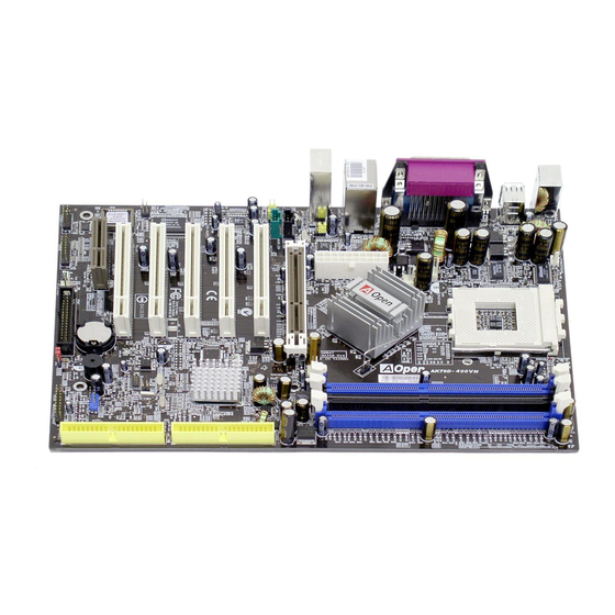
Page 16: Motherboard Map
FDD Connector Overheat Protection circuit to Athlon XP CPU only) IEEE1394 Connector x 2 (for AK79D-400 1394) nForce2 Ultra 400/MCP Chipsets (AK79D-400VN) JP14 CMOS Clear Jumper nForce2 Ultra 400/MCP-T Chipsets (AK79D-400 1394) Case Open Connector USB2.0 Connector 184-pin DIMMx3 supports... -
Page 17: Block Diagram
128bit dual channel DDR400/333/266 Up to 3GB DDR SDRAM Socket x3 32-bit PCI Slot x5 266/333/400MHz System Bus Socket 462 PCI Bus Primary Athlon/AthlonXP nForce2 Ultra 400 66/100/133 Channel IDE Drive x4 Secondary Channel AGP Bus AC’97 Link Audio CODEC AGP 8X Slot MCP-T VGA onboard... -
Page 18: Hardware Installation
This chapter describes jumpers, connectors and hardware devices of this motherboard. Note: Electrostatic discharge (ESD) can damage your processor, disk drives, expansion boards, and other components. Always observe the following precautions before you install a system component. Do not remove a component from its protective packaging until you are ready to install it. Wear a wrist ground strap and attach it to a metal part of the system unit before handling a component. -
Page 19: About "Manufacturer Upgrade Optional" And "User Upgrade Optional
When you read this online manual and start to assemble your computer system, you may find some of functions are called “Manufacturer Upgrade Optional”, and some are called “User Upgrade Optional”. Though all AOpen motherboards include many amazing and powerful features, in some situations, these powerful features are not used to every user. Hence, we changed some key features as “Manufacturer Upgrade Optional”... - Page 20 ® This motherboard supports AMD Athlon and Duron Socket 462 series CPU. Be careful of CPU orientation when you plug it into CPU socket (with CPU Overheat Protection function implemented, the system will be automatically powered off when CPU temperature reaches 97 degree, but it works on AthlonXP CPU only). 2.
-
Page 21: Cpu Installation
3. Press down the CPU socket lever and finish CPU installation. CPU cut edge Note: If you do not match the CPU socket Pin 1 and CPU cut edge well, you may damage the CPU. Note: This picture is for example only; it may not exactly be the same motherboard. -
Page 22: Aopen Overheat Protection (O.h.p.) Technology
O.H.P. (Overheat Protection) Technology to protect them. Thanks to the intelligent monitoring design of AOpen O.H.P. technology, user can now finally set their mind at ease even when fan failed to work without fearing the possible damage of CPU. -
Page 23: Cpu Over-Current Protection
CPU, memory, HDD, add-on cards installed on this motherboard may be damaged because of component failure, human operating error or unknown nature reason. AOpen cannot guaranty the protection circuit will always work perfectly. - Page 24 Tip: If your system hangs or fails to boot because of overclocking, simply use <Home> key to restore the default setting or you can wait the AOpen “Watch Dog ABS” reset the system after few seconds and system will auto-detect hardware again.
- Page 25 Core Frequency = CPU Clock * CPU Ratio EV6 Bus Speed = CPU external bus clock x 2 PCI Clock = CPU Bus Clock / Clock Ratio Clock = PCI Clock x 2 Core EV6 Bus Clock Ratio Frequency Athlon 1G 1GHz 266MHz 7.5x...
-
Page 26: Cpu And Housing Fan Connector
Plug in the CPU fan cable to the 3-pin CPUFAN1 connector. If you have chassis fan, you can also plug it on SYSFAN2 or SYSFAN3 connector. CPUFAN1 Connector +12V SENSOR SYSFAN2 Connector Note: Some CPU fans do not have sensor pin, so that they cannot support fan monitoring. -
Page 27: Enlarged Aluminum Heatsink
Cool down CPU and Chipset is important for system reliability. Enlarged aluminum heat sink provides better heat consumption especially when you are trying to over clocking the CPU. -
Page 28: Dimm Sockets (128-Bit Ddr Dual Channel)
In the past, we used to have 64-bit memory bandwidth for memory access. No matter how many memory modules have been installed, though capacity added, the speed of access remains the same. With 128-bit dual channel introduced, it doubles the memory bandwidth up to 5.4GB in advanced 128-bit mode. - Page 29 Please follow the procedure as shown below to finish memory installation. Make sure the DIMM module’s pin face down and match the socket’s size as depicted below. Pin 1 52 pins 40 pins Insert the module straight down to the DIMM slot with both hands and press down firmly until the DIMM module is securely in place.
-
Page 30: Atx Power Connector
The ATX power supply uses 20-pin connector shown below. Make sure you plug in the right direction. 20-Pin Power Connector A traditional ATX system should remain at power off stage when AC power resumes from power failure. This design is inconvenient for a network server or workstation, without an UPS, that needs to keep power-on. -
Page 31: Ide And Floppy Connector
Connect 34-pin floppy cable and 40-pin IDE cable to floppy connector FDD connector. Be careful of the pin1 orientation. Wrong orientation may cause system damage. FDD Connector Pin 1 ATA 66/100/133 IDE Connector IDE2 (Secondary) Pin 1 IDE1 (Primary) Pin1... - Page 32 IDE1 is also known as the primary channel and IDE2 as the secondary channel. Each channel supports two IDE devices that make a total of four devices. In order to work together, the two devices on each channel must be set differently to Master and Slave mode.
-
Page 33: Front Panel Connector
Attach the power LED, speaker, power and reset switch connectors to the corresponding pins. If you enable “Suspend Mode” item in BIOS Setup, the ACPI & Power LED will keep flashing while the system is in suspend mode. Locate the power switch cable from your ATX housing. It is 2-pin female connector from the housing front panel. -
Page 34: Agp (Accelerated Graphic Port) 8X Expansion Slot
Integrated GeForce4 MX Graphics, which provides the fastest integrated graphics performance and the most comprehensive set of features. This motherboard provides an 8x slot targeted for high-performance 3D graphic. AGP uses both rising and falling edge of the 66MHz clock, for 4X AGP, the data transfer rate is 66MHz x 4bytes x 4 = 1056MB/s. -
Page 35: Support Front Usb Connectors
This motherboard provides six connectors for you to connect USB devices such as mouse, keyboard, modem, printer, etc. There are four connectors on the back panel and one front USB connector on the board. You can use proper cables to connect the Front USB connector to USB modules or front panel of chassis. -
Page 36: Support 10/100 Mbps Lan Onboard
On the strength of NVIDIA LAN MAC embedded nForce2 Ultra 400 on chip (with RealTek RTL8201BL PHY), which are highly-integrated Platform LAN Connect devices, it provides 10/100M bps Ethernet for office and home use, the Ethernet RJ45 connector is located on top of USB connectors. The orange LED indicates the link mode; it lights when linking to network and blinking when transferring data. -
Page 37: Front Audio Connector
If the housing has been designed with an audio port on the front panel, you’ll be able to connect onboard audio to front panel through this connector. By the way, please remove 5-6 and 9-10 jumper caps from the Front Audio Connector before connecting the cable. -
Page 38: Color Coded Back Panel
The onboard I/O devices are PS/2 Keyboard, PS/2 Mouse, serial ports COM1, LAN, Printer, , AC97 sound and game port. The view angle of drawing shown here is the back panel of the housing. RJ45 10/100 PS/2 Mouse SPP/EPP/ECP Parallel Port LAN Jack Connector Line-In... -
Page 39: Super 5.1 Channel Audio Effect
This motherboard comes with an ALC650E CODEC, which supports high quality of 5.1 Channel audio effects, bringing you a brand new audio experience. On the strength of the innovative design of ALC650E, you're able to use standard line-jacks for surround audio output without connecting any external module. To apply this function, you have to install the audio driver in the Bonus Pack CD as well as an audio application supporting 5.1 Channel. -
Page 40: Com2 Connector
This motherboard provides two serial ports. One of them is on back panel connector, and the other is on the upper left of board. With proper cable, you can connect it to the back panel of chassis. Pin 1 DOD# SOUT DTR# CTS#... -
Page 41: Ieee 1394 Connectors (For Ak79D-400 1394)
With IEEE1394 MAC Embedded in nForce2 Ultra 400 (with AGERE FW802), the IEEE 1394 provides data transfer rate up to 400Mb/s, and USB1.0/1.1 just has 12Mbps. Hence, the IEEE 1394 interface can connect with the devices that need high data transferring performance, such as digital camera, scanner or others IEEE 1394 devices. -
Page 42: Irda Connector
The IrDA connector can be configured to support wireless infrared module. With this module and application software such as Laplink or Windows 95 Direct Cable Connection, user can transfer files to or from laptops, notebooks, PDA devices and printers. This connector supports HPSIR (115.2Kbps, 2 meters) and ASK-IR (56Kbps). Install infrared module onto IrDA connector and enable the infrared function from BIOS Setup, UART2 Mode. -
Page 43: Cnr (Communication And Network Riser) Expansion Slot
CNR is a riser card specification to replace the AMR (Audio/Modem Riser) that supports V.90 analog modem, multi-channel audio, and phone-line based networking. Owing to CPU computing power getting stronger, the digital processing job can be implemented in main chipset and share CPU power. The analogy conversion (CODEC) circuit requires a different and separate circuit design, which is put on CNR card. -
Page 44: Game Port Bracket Supported
This motherboard comes with a game port (Joystick-Midi) for you to connect any midi devices or joysticks. To use this function you have to have a joystick module and connect it with a game port cable to this port on the motherboard. Joystick Module (User Upgrade Optional) Pin1... -
Page 45: Cd Audio Connector
This connector is used to connect CD Audio cable from CD-ROM or DVD drive to onboard sound. Note: Though some of the latest Windows versions support “Digital Audio” through IDE bus, however, in order to use Open Jukebox player, which is driven under BIOS, it is a MUST to insert audio cable to CD-IN connector on the motherboard. -
Page 46: Aux-In Connector
This connector is used to connect MPEG Audio cable from MPEG card to onboard sound. AUX-IN... -
Page 47: Case Open Connector
The “CASE OPEN” header provides case open-monitoring function. To make this function work, you have to enable it in the system BIOS, connect this header to a sensor somewhere on the case. So, whenever the sensor is triggered by lights or when you open the chassis, the system will send out beep sound to inform you. -
Page 48: Stby (Standby) Led
STBY LED is AOpen’s considerate design that aims at providing you friendly system information. The STBY LED will light up when power is connected to the motherboard. This is a convenient indication for you to check the system power status in many circumstances such as power on/off, stand-by mode and RAM power status during Suspend to RAM mode. -
Page 49: Agp Protection Technology And Agp Led
With the outstanding R&D ability of AOpen and its specially developed circuit, this model implements a blend new technology to protect your motherboard from being damaged by over-voltaging of AGP card. When AGP Protection Technology is implemented, this motherboard will automatically detect the voltage of AGP card and prevent your chipsets from being burnt out. Please note that if you install a AGP card with 3.3V, which is not supported, the AGP LED on the motherboard will light up to warn you the... -
Page 50: Jp14 Clear Cmos Data
You can clear CMOS to restore system default setting. To clear the CMOS, follow the procedures below. Turn off the system and unplug the AC power. Remove ATX power cable from connector PWR2. Locate JP14 and short pins 2-3 for a few seconds. Return JP14 to its normal setting by shorting pin 1 &... -
Page 51: Jp27/28 Keyboard/Mouse Wakeup Jumpers
This motherboard provides USB and PS2 keyboard / mouse wake-up function. You can use JP27 / JP28 to enable or disable this function, which could resume your system from suspend mode with keyboard or mouse installed. JP28 controls 1 channel, and JP27 controls 2 USB channel. -
Page 52: 3 9 4 O N L I N E M A N U A L
This Motherboard implements Flash ROM and a special circuit that allows you to save your current CPU and CMOS Setup configurations without using the battery. The RTC (real time clock) can also keep running as long as the power cord is plugged. If you lose your CMOS data by accident, you can just reload the CMOS configurations from Flash ROM and the system will recover as usual. -
Page 53: Resetable Fuse
Traditional motherboard has fuse for Keyboard and port to prevent over-current or shortage. These fuses are soldered onboard that user cannot replace it when it is damaged (did the job to protect motherboard), and the motherboard remains malfunction. With expensive Resetable Fuse, the motherboard can resume back to normal function after fuse had done its protection job. -
Page 54: F Low Esr Capacitor
μ μ The quality of low ESR capacitor (Low Equivalent Series Resistance) during high frequency operation is very important for the stability of CPU power. The idea of where to put these capacitors is another know-how that requires experience and detail calculation. -
Page 55: Aoconfig Utility
Moreover, AOConfig allows users to save information in *.BMP or *.TXT format which users may collect the system information in detail and send them to AOpen directly for technical support or further diagnosis of system problem. The system page shows the... - Page 56 NOTE: AOConfig can be used in Windows 98SE/ME, NT4.0/2000, or even the latest Windows XP. Please be informed that AOConfig can only be operated in a system equipped with an AOpen motherboard. Meanwhile, all applications must be closed before starting AOConfig.
-
Page 57: Aopen "Watch Dog Abs
“ ” “ ” AOpen provides a special and useful feature on this motherboard for overclockers. When you power-on the system, the BIOS will check last system POST status. If it succeeded, the BIOS will enable “Watch Dog ABS” function immediately, and set the CPU FSB frequency according to user’s settings stored in the BIOS. -
Page 58: Phoenix Award Bios
The BIOS provides critical low-level support for standard devices such as hard disk drives, serial and parallel ports. Most BIOS setting of this model had been optimized by AOpen’s R&D engineering team. But, the default setting of BIOS still can’t fine-tune the chipset controlling the entire system. Hence, the rest of this chapter is intended to guide you through the process of configuring your system using setup procedures. -
Page 59: How To Use Phoenix Award™ Bios Setup Program
The following table provides details about how to use keyboard in the Phoenix-Award™ BIOS setup program. Alternatively, it's strongly recommended to install AOpen’s newest WinBIOS Utility to get more detailed description, further powerful functions and advanced setting of BIOS. -
Page 60: How To Enter Bios Setup
After you finish the setting of jumpers and connect correct cables. Power on and enter the BIOS Setup, press <Del> during POST (Power-On Self Test) . Choose " Load Setup Defaults" for recommended optimal performance. Warning: Please avoid of using "Load Turbo Defaults", unless you are sure your system components (CPU, SDRAM, HDD, etc.) are good enough for turbo setting. -
Page 61: Winbios Utility
POST (Power-On-Self-Test) screen to get into the BIOS, which is inconvenient and clumsy. From now on, AOpen provides an easier way to configure your BIOS. WinBIOS is a customized utility for running exclusively on AOpen motherboards, which allows you to setup your BIOS under Windows environment. - Page 62 BIOS from damaged by wrong profile version. For the latest WinBIOS profile and language pack modules, you may find them from AOpen official web site as shown below: ( http://english.aopen.com.tw/tech/download/WinBIOS/default.htm ) Note: Due to BIOS versions are updated in an extremely...
-
Page 63: Bios Upgrade Under Windows Environment
NT4.0/2000, or even the latest Windows XP. In the meanwhile, in order to provide a much more user-friendly operating environment, AOpen EzWinFlash is natively designed to have multi-language function to provide easier way for users’ usage in changing BIOS setting. - Page 64 You may accomplish BIOS upgrade procedure with EzWinFlash by the following steps, and it’s STRONGLY RECOMMENDED to close all the applications before you start the upgrading. 1. Download the new version of BIOS package zip file from AOpen official web site. (ex: http://english.aopen.com.tw/ 2.
-
Page 65: Open Jukebox Player
Here we are pleased to provide you a brand-new powerful interface—Open JukeBox. Without any cost you can have your PC turn into a fashionable CD player! This latest Open JukeBox motherboard aims at helping you directly operate your CD player on the PC without any hassle of entering Windows operation system. - Page 66 How Your Open JukeBox Works The operation of Open JukeBox Player is the same as other CD players. By pressing specific keys on the keyboard you will find playing Open JukeBox Player couldn’t be easier than the traditional CD Players. Below is the function description of respective buttons.
- Page 67 Your Open JukeBox Settings in BIOS There are three Open JukeBox settings in BIOS as follows. Auto: The default setting is “Auto” with which the Open JukeBox will automatically check the CD player every time you power on. The Open JukeBox will automatically be launched when it detects a music CD in your CD player. Press Insert Key: Choosing this setting will allow a reminder message popped up on the screen during BIOS POST.
- Page 68 Except these powerful functions above, Open JukeBox Player is also equipped with another fancy feature for you to change its “skin”. You can download as many skins as you want from AOpen Website, and changing them whenever you want by using this useful utility – EzSkin – which may also be downloaded from our website.
-
Page 69: Vivid Bios Technology
VividBIOS to experience the lively vivid colourful POST screen! Unlike earlier graphic POST screen, which could occupy the whole screen and mask text information during POST, AOpen VividBIOS deals with graphics and texts separately, and makes them running simultaneously during POST. With this innovative design, VividBios now brings you a beautiful and sleek 256 colours screen without missing any important information shown on POST screen. -
Page 70: The Noise Is Gone
Today, AOpen Motherboard is honored to bring you a new overall solution, SilentTek, to make your system quiet. To collocate... - Page 71 In “Temp/Fan/Case” page, you may get aware of the The first image you have here is the Voltage Status current temperature of CPU and the heat inside chassis. page. You can find current status of all voltages and set your expected margins of warning level. Also, you can check if fans are running properly.
- Page 72 You may find that this setting fits you best. AOpen Recommend Setting: This setting is designed specifically for AOpen housing. A series of lab tests were conducted under the real world scenario to determine optimum fan speed to reduce noise level within CPU working condition and temperature.
-
Page 73: Ezclock
But from now on, you don’t have to surfer the boring stuffs anymore. With brand-new and user-friendly EzClock that AOpen specially designs for his users, you can adjust those important values as you please and think of suitable. - Page 74 How You Adjust the Settings in EzClock Utility In EzClock utility, you can adjust CPU Front Side Bus (FSB), the voltage and frequency of VGA, AGP, PCI and DRAM. Besides, the CPU related information such as CPU voltage, temperature and CPUFAN rotation speed will also be displayed on this utility. On the left circle area shows Ratio, FSB and frequency information CPU Color Bars: The color bar will...
- Page 75 On the bottom rectangular panel represents CPU fan speed, CPU voltage and CPU temperature. The three color bars on the right hand side will light on according to operation temperature. Please refer to the picture shown above. CPU Color Bars: CPU Fan, Voltage and Temperature: The color bars will light on representing CPU fan speed, CPU...
- Page 76 How Your Boot Screen Looks Like After you finish setting BIOS, these setting values will be displayed on the boot screen like the shown picture here. Every time you boot your system, both default and current settings will pop up on the screen. Your personal settings that had been adjusted earlier will be highlighted;...
-
Page 77: Driver And Utility
There are motherboard drivers and utilities included in AOpen Bonus CD. You don’t need to install all of them in order to boot your system. But after you finish the hardware installation, you have to install your operation system first (such as Windows 2000/XP) before you can install any drivers or utilities. -
Page 78: Nvidia Nforce Windows Driver
This nForce driver is an all in one package, which contains the below components: Audio driver, Audio utilities, Network driver, GART driver, SMBus driver, Memory controller driver. -
Page 79: Nvidia Usb2.0 Driver
NOTICE: If you have install Windows XP Service Pack1, it is not necessary to install USB2.0 driver. USB2.0 driver had been packaged in Service Pack1 *********************************************** Installing Driver in Existing Windows XP System *********************************************** Please follow these directions for a smooth installation of the USB 2.0 package. After enabling the USB 2.0, Windows XP setup will show a "Found New Hardware"... - Page 80 * for Windows 98SE/ME/2000 Installation...
-
Page 81: Glossary
Basically, AC97 CODEC is the standard structure of PCI sound card. As we know, computer is digital-based, but music is based on analog-based. Therefore, there must be a process to turn digital into analog during the last stage processing of sound in computer. -
Page 82: Agp (Accelerated Graphic Port)
The main function of AGP simply put is to tell monitor what screen information had to be shown, a visual transmission device actually. With the rapid developing of AGP card, we can see that it had been developed from single colorful AGP card to 2D and 3D graphic. -
Page 83: Bios (Basic Input/Output System)
and integrated drive controller and the computer's motherboard. Two drives (master and slave) are supported. The ATA specification allows the drive to connect directly to the ISA bus on the computer. ATA transfer rate then had been developed to 133MHz/Sec and would come out with fastest rate later (please refer to Serial ATA DMA, data transfer rate is 16.6MHz/s. -
Page 84: Cnr (Communication And Networking Riser)
high transfer rate of 1MB/s, it also could be encrypted with pin code. With hopping rate of 1600 hops per second, it’s difficult to be intercepted and are less interrupted by electromagnetic wave. The CNR specification provides the PC industry the opportunity to deliver a flexible and cost reduced method of implementing LAN, home networking, DSL, USB, wireless, audio and modem subsystems widely used in today's "connected PCs". -
Page 85: Ecc (Error Checking And Correction)
The ECC mode needs 8 ECC bits for 64-bit data. Each time memory is accessed; ECC bits are updated and checked by a special algorithm. The ECC algorithm has the ability to detect double-bit error and automatically correct single-bit error while parity mode can only detect single-bit error. -
Page 86: Fcc Doc (Declaration Of Conformity)
The DoC is component certification standard of FCC EMI regulations. This standard allows DIY component (such as motherboard) to apply DoC label separately without a shielding of housing. FC means Flip Chip, FC-PGA is a package of Intel for Pentium III for 0.18µm process CPU, which can be plugged into SKT370 socket. -
Page 87: Ieee 1394
IEEE 1394, which also called Firewire, is a serial data transfer protocol and interconnection system. The main feature of the Firewire that assures its adoption for the digital video and audio (A/V) consumer application is its low cost. Fire wire interface is capable of supporting various high-end digital A/V applications, such as consumer A/V device control and signal routing, Digital Video (DV) editing, home networking, and more than 32 channels of digital mixing. -
Page 88: Pci (Peripheral Component Interface) Bus
Developed by Intel, Peripheral Component Interconnect (PCI) is a local bus standard. A bus is a channel used to transfer data to (input) and from (output) a computer and to or from a peripheral device. Most PCs have a PCI bus usually implemented at 32-bits providing a 33 MHz clock speed with a throughput rate of 133 MBps. -
Page 89: Psb (Processor System Bus) Clock
PSB Clock means the external bus clock of CPU. CPU internal clock = CPU PSB Clock x CPU Clock Ratio A DRAM technology developed by Rambus Corporation*, to achieve high speed of memory through the use of multiple channels in parallel by 16-bits. Basically, RDRAM uses new structure of Multibank, which is quite different from FPM, EDO, SDRAM. Using different memory module as well, RDRAM uses “RIMM”... -
Page 90: Sata (Serial Ata)
The Serial ATA specification is designed to overcome speed limitations while enabling the storage interface to scale with the growing media rate demands of PC platforms. Serial ATA is to replace parallel with the compatibility with existing operating systems and drivers, adding performance headroom for years to come. It is developed with data transfer rate of 150 Mbytes/second, and 300M/bs, 600M/bs to come. -
Page 91: Vcm (Virtual Channel Memory)
system automatically recognize the change. USB 2.0, which supports data transfer rates of 480 Mbps, has been widely used in motherboard these days. NEC’s Virtual Channel Memory (VCM) is a new DRAM core architecture that dramatically improves the memory system’s ability to service multimedia requirements. -
Page 92: Troubleshooting
If you encounter any trouble to boot you system, follow the procedures accordingly to resolve the problem. Start Turn off the power and unplug the AC power cable, then remove all of the add-on cards and cables, including VGA, IDE, FDD, COM1, COM2 and printer. - Page 93 Continue Install the VGA card. Then connect your monitor and keyboard. Turn on the power and check if the power supply and CPU fan work properly. The problem is probably caused by power supply or motherboard failure Next Please contact your reseller or local distributor for repairing.
- Page 94 Continue Perhaps your VGA card Check if there is display? or monitor is defective. Press <Ctrl> and <Alt> key at the same time, hold them and then press <Del> to reboot the system. It is very possible that your Check if the system keyboard is defective.
- Page 95 Continue During system rebooting, press <Del> to enter BIOS setup . Choose “Load Setup Default ”. Turn off the system and re-connect IDE cable. The problem should be Check if the system can caused reboot successfully? cable or HDD itself Re-install the operating system such as Windows 98.
-
Page 96: Technical Support
Dear Customer, Thanks for choosing AOpen products. To provide the best and fastest service to our customer is our first priority. However, we receive numerous emails and phone-calls worldwide everyday, it is very hard for us to serve everyone on time. We recommend you follow the procedures below and seek help before contact us. - Page 97 We welcome you to join AOpen eForum to discuss our products with other users. Your problem probably had been discussed before or will be answered by other power users here. http://club.aopen.com.tw/forum / Contact Distributors/Resellers: We sell our products through resellers and integrators. They should know your system configuration very well and should be able to solve your problem efficiently and provide important reference for you.
- Page 98 Model name and BIOS version can be found on upper left corner of first boot screen ( POST screen). For example: AK79D-400 1394 R1.02 Sep. 01.2003 AOpen Inc. Award Plug and Play BIOS Extension v1.0A Copyright © 2003, Award Software, Inc.
-
Page 99: Product Registration
Be able to join the discussions of web-based news groups. AOpen makes sure that the information you provide is encrypted, so that it cannot be read or intercepted by other people or companies. Further, AOpen will not disclose any of information you submitted under any conditions. Please consult our... -
Page 100: How To Contact Us
Please do not hesitate contact us if you have any problem about our products. Any opinion will be appreciated. Pacific Rim Europe America AOpen Inc. AOpen Computer b.v. AOpen America Inc. Tel: 886-2-3789-5888 Tel: 31-73-645-9516 Tel: 1-510-489-8928 Fax: 886-2-3789-5899 Email: Support@AOpen.NL...
Need help?
Do you have a question about the AK79D-400VN and is the answer not in the manual?
Questions and answers