
Related Manuals for AOpen AX4C Max II


Summary of Contents for AOpen AX4C Max II
-
Page 1: Ax4C Max Ii
AX4C Max II DOC. NO.: AX4CMAXII-OL-E0403C... -
Page 2: Table Of Contents
’ ’ AX4C Max II ........................... 1 What’s in this manual ..............................2 You Must Notice................................9 Before You Start ................................10 Overview..................................11 Feature Highlight ................................12 Quick Installation Procedure ............................17 Motherboard Map ................................. 18 Block Diagram ................................19 Hardware Installation ....................... - Page 3 DIMM Sockets (128-Bit DDR Dual Channel) ......................... 31 Front Panel Connector ..............................34 ATX Power Connector..............................35 AC Power Auto Recovery ............................. 36 STBY LED and BOOT LED ............................37 IDE and Floppy Connector ............................38 ATA/133 Supported ............................... 41 Serial ATA Supported (with RAID function) ........................
- Page 4 Support Eight USB2.0 Connectors ..........................59 Onboard IEEE 1394 Controller ............................. 60 Chassis Intrusion Connector ............................61 CD Audio Connector ..............................62 AUX-IN Connector ................................ 63 Front Audio Connector ..............................64 Die-Hard BIOS II (User Upgrade Optional) ........................65 External Controller for DIE-HARD BIOS (User Upgrade Optional) ................66 JP2 Dr.
- Page 5 RAID Introduction ........................86 What’s RAID? ................................86 What are the RAID levels? ............................87 HDD Capacity of RAID Levels ............................90 Serial ATA RAID for Intel ICH5R ........................... 91 Serial ATA RAID for Promise PDC20378 ........................94 Driver and Utility ........................111 Auto-run Menu from Bonus CD Disc ..........................111 Installing Intel®...
- Page 6 Glossary ..........................146 AC97 CODEC ................................146 ACPI (Advanced Configuration & Power Interface) ..................... 146 ACR (Advanced Communication Riser) ........................146 AGP (Accelerated Graphic Port) ..........................147 AMR (Audio/Modem Riser) ............................147 ATA (AT Attachment) ..............................147 BIOS (Basic Input/Output System) ..........................148 Bluetooth ..................................
- Page 7 Hyper Threading ................................. 151 IEEE 1394 .................................. 152 Parity Bit ..................................152 PCI (Peripheral Component Interface) Bus ......................... 153 PDF Format ................................153 PnP (Plug and Play)..............................153 POST (Power-On Self Test) ............................153 PSB (Processor System Bus) Clock ........................... 154 RDRAM (Rambus Dynamic Random Access Memory) ....................
- Page 8 Technical Support ........................162 Product Registration ....................... 165 How to Contact Us ........................166...
-
Page 9: You Must Notice
All of the specifications and information contained in this manual are subject to change without notice. AOpen reserves the right to revise this publication and to make reasonable changes. AOpen assumes no responsibility for any errors or inaccuracies that may appear in this manual, including the products and software described in it. -
Page 10: Before You Start
This Online Manual will introduce to the user how this product is installed. All useful information will be described in later This Online Manual will introduce to the user how this product is installed. All useful information will be described in later chapters. -
Page 11: Overview
® Thank you for choosing AOpen AX4C Max II motherboard. The AX4C Max II is Intel Socket 478 motherboard (M/B) based on the ATX form factor featuring the Intel® 875P (Canterwood) chipset . As high performance chipset built in the M/B, the AX4C ®... -
Page 12: Feature Highlight
® ® Supports Intel Socket 478 Pentium 4 1.6GHz~3.06GHz+ with 800/533MHz Front Side Bus (FSB) designed for Socket 478 technology. Chipset ® With the Intel 875P (Canterwood) chipset, Intel delivers a discrete graphics solution with all the performance, innovative ® features and proven reliability of the Intel 875P (Canterwood) chipset. - Page 13 Memory Providing ECC four 184-pin DDR DIMM sockets that support up to 4GB of DDR400/333 compliant DDR RAM. You may install 128, 256, 512MB or 1GB DDR RAM DIMM modules into each socket. LAN Port Broadcom Gigabit PCI LAN Chip, which is an highly-integrated Platform LAN Connect device, it provides Gigabits or 10/100Mbps Ethernet for office and home use.
- Page 14 100~400 by 1MHz stepping adjustment, and lets your system can get maximum performance. Watch Dog ABS Includes AOpen “Watch Dog ABS” function, which could auto-reset default settings in 4.8 seconds when you fail to system overclocking. Die-Hard BIOS II (User Upgrade Optional) The Die-Hard BIOS technology is a very effective hardware protection method that doesn’t involve any software or BIOS coding.
- Page 15 Dr. LED (User Upgrade Optional) Dr. LED has 8 LEDs on this AX4C Max II M/B to easily show what kind of problems you may encounter. Power Management/Plug and Play Support the power management function that confirms to the power-saving standards of the U.S. Environmental Protection Agency (EPA) Energy Star program.
- Page 16 Enhanced ACPI ® Fully implement the ACPI standard for Windows 98/ME/2000/XP series compatibility, and supports Soft-Off, STR (Suspend to RAM, S3), STD (Suspend to Disk, S4) features. Super Multi-I/O Provide two high-speed UART compatible serial ports and one parallel port with EPP and ECP capabilities. UART can also be directed from COM1or COM2 to the Infrared Module for the wireless connections.
-
Page 17: Quick Installation Procedure
This page gives you a quick procedure on how to install your system. Follow each step accordingly. Installing CPU and Fan Installing System Memory (DIMM Connecting Front Panel Cable Connecting IDE and Floppy Cable Connecting ATX Power Cable Connecting Back Panel Cable Power-on and Load BIOS Setup Default Setting CPU Frequency Reboot... -
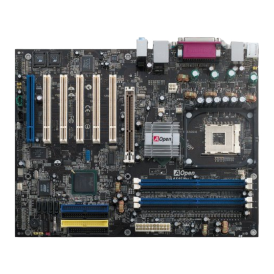
Page 18: Motherboard Map
Broadcom Gigabit PCI LAN Chip Motherboard Map Onboard AC’97 CODEC S/PDIF Connector PC99 Colored Back Panel Die-Hard BIOS (BIOS1 & 2) (User Upgrade Optional) Resetable Fuse GAME Connector JP28 Keyboard/Mouse Wakeup Enable/Disable Jumper Front Audio Connector 4-pin 12V. ATX Power Connector AGP LED V4 Power Engine AUX-IN Connector... -
Page 19: Block Diagram
Self- Powered PCI slot DDR400/333 DDR RAM Up to 32-bit PCI Slot x6 PCI Bus SATA Drive x2 Promise DIMM Socket x4 PDC20378 Serial ATA Third Channel Socket 478 800/533MHz ATA 133 Intel System Bus Pentium 4 Primary Channel IDE Drive x6 33/66100 Secondary Intel 875P... -
Page 20: Hardware Installation
This chapter describes jumpers, connectors and hardware devices of this motherboard. This chapter describes jumpers, connectors and hardware devices of this motherboard. Note: Electrostatic discharge (ESD) can damage your processor, disk drives, expansion boards, and other components. Always observe the following precautions before you install a system component. Do not remove a component from its protective packaging until you are ready to install it. -
Page 21: About "Manufacturer Upgrade Optional" And "User Upgrade Optional
When you read this online manual and start to assemble your computer system, you may find some of functions are called “Manufacturer Upgrade Optional”, and some are called “User Upgrade Optional”. Though all AOpen motherboards include many “Manufacturer Upgrade Optional”, and some are called “User Upgrade Optional”. Though all AOpen motherboards include many amazing and powerful features, in some situations, these powerful features are not used to every user. -
Page 22: Jp14 Clear Cmos Data
You can clear CMOS to restore system default setting. To clear the CMOS, follow the procedure below. Turn off the system and unplug the AC power. Remove ATX power cable from connector PWR2. Locate JP14 and short pins 2-3 for a few seconds. Return JP14 to its normal setting by shorting pins 1 &... - Page 23 ® ® This motherboard supports Intel This motherboard supports Intel Pentium 4 Socket 478 series CPU. Be careful of CPU orientation when you plug it into CPU Pentium 4 Socket 478 series CPU. Be careful of CPU orientation when you plug it into CPU socket.
-
Page 24: Cpu Installation
3. Press down the CPU socket lever and finish CPU installation. CPU cut edge Note: If you do not match the CPU socket Pin 1 and CPU cut edge well, it may damage the CPU. Note: This socket supports Micro-FC-PGA2 package CPU, which is the latest CPU package developed by Intel. -
Page 25: Cpu Jumper-Less Design
CPU VID signal and CPU VID signal and SMbus SMbus clock generator provide CPU voltage auto-detection and allows the user to set the CPU frequency through the BIOS setup , therefore no jumpers or switches are used. The disadvantages of the Pentium based jumper-less designs are eliminated. - Page 26 “ ” ” With this motherboard, AOpen provides a very special, useful feature for overclockers. With this motherboard, AOpen provides a very special, useful feature for overclockers. When you power-on the system, the BIOS will check last system When you power-on the system, the BIOS will check last system...
-
Page 27: Cpu Core Voltage Auto Detectable
Tip: The North Bridge of Canterwood restore the default setting or you can wait the does supports “Turbo mode”, which is Home AOpen “Watch Dog ABS” reset the system after used to lower latency paths from FSB five seconds system... - Page 28 Core Frequency = CPU Clock * CPU Ratio PCI Clock = CPU FSB Clock / Clock Ratio Clock = PCI Clock x 2 Note: Since the latest processor, CPU Core Northwood CPU FSB Clock System Bus Ratio Northwood, would detect the clock Frequency ratio automatically, you may not be Pentium 4...
-
Page 29: Cpu And System Fan Connector (With H/W Monitoring)
Plug in the CPU fan cable to the 3-pin CPUFAN1 connector. If you have chassis fan, you can also plug it on SYSFAN2 or SYSFAN3 connector. +12V SENSOR CPUFAN1 Fan Connector +12V SENSOR SYSFAN2 Connector SENSOR Note: Some CPU fans do not have +12V sensor pin, so that cannot support hardware monitoring function. -
Page 30: Jp28 Keyboard/Mouse Wake-Up Enable/Disable Jumper
This motherboard provides keyboard / mouse wake-up function. You can use JP28 to enable or disable this function, which could resume your system from suspend mode with keyboard or mouse installed. The factory default setting is set to “Disable”(1-2), and you may enable this function by setting the jumper to 2-3. Pin 1 JP28 KB/Mouse Wake-up... -
Page 31: Dimm Sockets (128-Bit Ddr Dual Channel)
This motherboard has four 184-pin DDR DIMM sockets that allow you to install DDR400 DDR333 memory up to 4 GB. ECC DDR RAM is supported. Newly implemented function, the Voltage of memory on this motherboard is adjustable from 2.5V to 2.85V (such as 2.5V, 2.55V, 2.6V, 2.65V, 2.7V, 2.75V, 2.8V, 2.85V) for over clocking purpose, but default value here is 2.55V. - Page 32 Dual Channel memory configuration provides higher performance than single channel configuration. To get the highest Dual Channel memory configuration provides higher performance than single channel configuration. To get the highest performance of Dual Channel, the DIMM modules you’re using must meet the following conditions: performance of Dual Channel, the DIMM modules you’re using must meet the following conditions: Same DRAM technology (128Mb, 256Mb, or 512Mb) Same DRAM technology (128Mb, 256Mb, or 512Mb)
- Page 33 Please follow the procedure as shown below to finish memory installation. Please follow the procedure as shown below to finish memory installation. Make sure the DIMM module’s pin face down and match the socket’s size as depicted below. Make sure the DIMM module’s pin face down and match the socket’s size as depicted below. 40 pins 52 pins Insert the module straight down to the DIMM slot with both hands and press down firmly until the DIMM module is securely...
-
Page 34: Front Panel Connector
Attach the power LED, speaker, power and reset switch connectors to the corresponding pins. If you enable “Suspend Mode” item in BIOS Setup, the ACPI & Power LED will keep flashing while the system is in suspend mode. Locate the power switch cable from your ATX housing. It is 2-pin female connector from the housing front panel. -
Page 35: Atx Power Connector
This motherboard comes with a 20-pin and 4-pin ATX power connector. Make sure you plug in the right direction. We strongly recommend you to connect the 4-pin 12V ATX connector before connecting the 20-pin ATX power connector and use standard power supply specially designed for Pentium 4 system. -
Page 36: Ac Power Auto Recovery
A traditional ATX system should remain at power off stage when AC power resumes from power failure. This design is inconvenient for a network server or workstation, without an UPS, that needs to keep power-on. This motherboard implements an AC Power Auto Recovery function to solve this problem. -
Page 37: Stby Led And Boot Led
Both STBY LED and BOOT LED are AOpen’s considerate designs that aim at providing you friendly system information. The STBY LED will light up when power is provided to the motherboard. This is a convenient indication for you to check the system power status in many circumstances such as power on/off, stand-by mode and RAM power status during Suspend to RAM mode. -
Page 38: Ide And Floppy Connector
Connect 34-pin floppy cable and 40-pin IDE cable to floppy connector FDD and IDE connector. The blue connector is IDE1 for clear identification. Be careful of the pin1 orientation. Wrong orientation may cause system damage. Primary Primary Slave (2nd) Master (1st) IDE 1 (Primary) IDE 2 (Secondary) Pin 1... - Page 39 IDE1 is also known as the primary channel, IDE2 and IDE3 are known as the secondary and third channel. Each channel supports two IDE devices that make a total of six devices. In order to work together, the two devices on each channel must be set differently to Master and Slave mode.
- Page 40 By the strength of Promise PDC29378, you will find an extra IDE 3 onboard for the scalability of hard disks capacity. All you have to do is to simply set the following configuration to make full advantage of it. Please press Ctrl-F to get into the Promise PDC29378 BIOS during POST. Select Auto Setup for the system to recognize your hard disk, and done.
-
Page 41: Ata/133 Supported
This motherboard supports ATA66 ATA100 ATA133 IDE devices. Following table lists the transfer rate of IDE PIO and DMA modes. The IDE bus is 16-bit, which means every transfer is two bytes. As the hard drive industry introduces faster and higher capacity hard drives, the current Ultra ATA/100 interface causes a data bottleneck between the drive and the host computer. -
Page 42: Serial Ata Supported (With Raid Function)
SATA port 2 (ICH5R) SATA port 1 (ICH5R) SATA port 3 (PDC20378) SATA port 4 (PDC20378) Serial ATA Ports Motherboard SATA 1 & 2 SATA 3 & 4 AX4C Max II RAID 0, 1 RAID 0, 1, 0+1 (With ATA133) -
Page 43: Connecting Serial Ata Disk
To connect a Serial ATA disk, you have to have a 7-pin serial ATA cable. Connect two ends of the serial ATA cable to the serial To connect a Serial ATA disk, you have to have a 7-pin serial ATA cable. Connect two ends of the serial ATA cable to the serial ATA header on the motherboard and the disk. - Page 44 Except its original 2 sets of parallel IDE, this motherboard does come with the support for the latest Serial ATA hard disk. If you are unable to find your newly installed Serial ATA hard disks on your operating system after you have had installed them on, the problem mainly lies in the BIOS setting.
- Page 45 If you intend to change the default setting, simply press Enter for a list of selection: Disabled: You may choose this item if you’re sure that only traditional IDE hard disks had been installed on your system. Disabling this item may also cancel the detection to Serial ATA hard disk during POST, which theoretically, could speed up your boot-up timing for a little bit;...
-
Page 46: Irda Connector
The IrDA connector can be configured to support wireless infrared module, with this module and application software such as Laplink or Windows 95 Direct Cable Connection, the user can transfer files to or from laptops, notebooks, PDA devices and printers. This connector supports HPSIR (115.2Kbps, 2 meters) and ASK-IR (56Kbps). Install the infrared module onto the IrDA connector and enable the infrared function from BIOS Setup, UART Mode, make sure to have the correct orientation when you plug in the IrDA connector. -
Page 47: S/Pdif (Sony/Philips Digital Interface) Connector
S/PDIF (Sony/Philips Digital Interface) is a newest audio transfer file format, which provides impressive audio quality through optical fiber and allows you to enjoy digital audio instead of analog audio. Normally there are two S/PDIF outputs as shown, one for RCA connector, the most common one used for consumer audio products, and the other for optical connector with better audio quality. -
Page 48: Super 5.1 Channel Audio Effect
This motherboard comes with an ALC650 CODEC, which supports high quality of 5.1 Channel audio effects, bringing you a brand new audio experience. On the strength of the innovative design of ALC650, you're able to use standard line-jacks for surround audio output without connecting any external module. To apply this function, you have to install the audio driver in the Bonus Pack CD as well as an audio application supporting 5.1 Channel. -
Page 49: Agp 8X Slot
64MHz to 100MHz through BIOS. Additionally, AOpen provide sets of AGP/PCI frequencies for overclockers to manually overclock AGP/PCI frequency while taking care of the system stability at the same time (but will be automatically disabled when connecting any Serial ATA device). -
Page 50: Agp Protection Technology And Agp Led
& & AGP LED Warning: It is strongly recommended not to install a 3.3V AGP card, which is not supported. When you do so, the AGP LED on the motherboard will light up to warn you the possible damage. -
Page 51: Self-Powered Pci Slot
Spotted easily among other PCI slots onboard, this Self-Powered PCI slot comes in a special BLUE color to illustrate its uniqueness and usefulness. As independent as it is, Self-Powered PCI comes in a separate set of 3.3 volt power circuitry which supplies needed current and making it virtually free from the “loading issue”... -
Page 52: Wom (Zero Voltage Wake On Modem) Connector
This motherboard implements special circuit to support Wake On Modem, both internal modem card and external box modem are supported. Since internal modem card consumes no power when system power is off, it is recommended to use an internal modem. To use internal modem, connect 4-pin cable from RING connector of modem card to the WOM connector on the motherboard. - Page 53 Traditional Green PC suspend mode does not really turn off the system power supply, it uses external box modem to trigger MB COM port and resume back to active. Serial Port (Modem Side) Pin 1 Pin 1 Serial Port (Motherboard Side) Note: This picture is for example only;...
- Page 54 With the help of the ATX soft power On/Off, it is possible to have a system totally power off, and wakeup to automatically answer a phone call as an answering machine or to send/receive a fax. You may identify whether or not your system is in true power off mode by checking to see if the fan of your power supply is off.
-
Page 55: Wol (Wake On Lan)
This feature is very similar as Wake On Modem , but it goes through local area network. To use Wake On LAN function, you must have a network card with chipset that supports this feature, and connect a cable from LAN card to motherboard WOL connector. - Page 56 WOL Connector (Ethernet Card Side) WOL Connector (Motherboard Side) Note: This picture is for example only, it may not exactly be the same motherboard. Note: This picture is for example only, it may not exactly be the same motherboard.
-
Page 57: Pc99 Color Coded Back Panel
The onboard I/O devices are PS/2 Keyboard, PS/2 Mouse, COM1 and COM2, RJ45 LAN, Printer, USB2.0 , AC97 sound and game ports. The view angle of drawing shown here is from the back panel of the housing. PS/2 Mouse SPP/EPP/ECP RJ45 LAN Jack Connector Parallel Port... -
Page 58: Support Gigabit Lan Onboard
On the strength of Broadcom Gigabit LAN controller on board, which is a highly-integrated Platform LAN Connect device, it provides Gigabits Ethernet for office and home use, the Ethernet RJ45 connector is located on top of USB connectors. The right-hand side LED indicates the link mode, it blinks in orange whenever linking to network. The left-hand side LED indicates the Connecting mode, and it lights in green when 100Mbps LAN is connected (never lights while 10Mbps is connected), but lights in orange when Gigabits LAN is connected. -
Page 59: Support Eight Usb2.0 Connectors
Compared to traditional USB 1.0/1.1 with the speed of 12Mbps, USB 2.0 has a fancy speed up to 480Mbps, which is 40 times faster than the traditional one. Except for the speed increase, USB 2.0 supports old USB 1.0/1.1 software and peripherals, offering impressive and even better compatibility to customers. -
Page 60: Onboard Ieee 1394 Controller
This motherboard comes with AGERE 1394 Control Chip (FW323) onboard. The IEEE 1394 provides data transfer rate up to 400Mbps, and USB just has 12Mbps. Hence, the IEEE 1394 interface can connect with the devices that need high data transferring performance, such as digital camera, scanner or others IEEE 1394 devices. Please use the proper cable to connect with devices. -
Page 61: Chassis Intrusion Connector
The “CASE OPEN” header provides chassis intrusion-monitoring function. To make this function works, you have to enable it in the system BIOS, connect this header to a sensor somewhere on the chassis. So, whenever the sensor is triggered by lights or the opening of the chassis, the system will send out beep sound to inform you. -
Page 62: Cd Audio Connector
This connector is used to connect CD Audio cable from CDROM or DVD drive to onboard sound. Note: Though some of the latest version of Windows support “Digital Audio” through IDE bus. However, in order to use Open Jukebox player, which is driven under BIOS, it is a MUST to insert audio cable to CD-IN connector on the motherboard. -
Page 63: Aux-In Connector
This connector is used to connect MPEG Audio cable from MPEG card to onboard sound. -
Page 64: Front Audio Connector
If the housing has been designed with an audio port on the front panel, you’ll be able to connect onboard audio to front panel through this connector. By the way, please remove 5-6 and 9-10 jumper caps from the Front Audio Connector before connecting the cable. -
Page 65: Die-Hard Bios Ii (User Upgrade Optional)
Many viruses have been found that they may destroy bios code and data area lately. This motherboard implements a very effective hardware protection method without any software or BIOS coding involved, therefore it is 100% virus free. You may restore the originally mounted BIOS with 2 BIOS ROM by setting JP24 to pin 2-3 if it fails to work properly. -
Page 66: External Controller For Die-Hard Bios (User Upgrade Optional)
External Controller provides you a better and convenience way to switch the BIOS status between “Rescue” and “Normal” without opening the case of your computer. You have to plug the jumper cable to the connector pin (JP30) on the motherboard. Be careful of the orientation when you connect, the red wire should correspond to Pin1. - Page 67 Turn off the system, set the External Controller to “Rescue” to read from rescue ROM. Turn off the system, set the External Controller to “Rescue” to read from rescue ROM. Boot the system and set the switch back to “Normal”. Boot the system and set the switch back to “Normal”.
-
Page 68: Jp2 Dr. Voice Output Select Jumper
This motherboard comes with another considerate function, which allows you to select the voice coming out from buzzer or speaker, if Dr. Voice detects any errors that occurred in the operating system. If you want to enable buzzer, you may set JP2 to pin 1-2, or pin 2-3 to enable speaker. -
Page 69: Dr. Led Connector
In conjunction with Dr. LED (Upgrade Optional), which can easily shows what kind of problems may occur on your system during assembly. It can clearly indicate whether there is a component issue or an installed issue by the 8 LEDs on the front panel of Dr. LED. - Page 70 Dr. LED is a CD disc storage box with 8 LEDs on its front panel, the size of Dr. LED is exactly the same as 5.25 in floppy drive, Dr. LED is a CD disc storage box with 8 LEDs on its front panel, the size of Dr. LED is exactly the same as 5.25 in floppy drive, so that it can be mount into normal 5.25 in drive bay of any housing.
-
Page 71: Battery-Less And Long Life Design
This Motherboard implements This Motherboard implements Flash ROM Flash ROM and a special circuit that allows you to save your current CPU and CMOS Setup configurations without the need of a battery. The RTC (real time clock) can also keep running as long as the power cord is plugged. -
Page 72: Cpu Over-Current Protection
CPU, memory, HDD, add-on cards installed on this motherboard may be damaged because of component failure, human operating error or unknown nature reason. AOpen cannot guaranty the protection circuit will always work perfectly. -
Page 73: Aoconfig Utility
Moreover, AOconfig allows users to save information in *.BMP or *.TXT format which users may collect the system information in detail and send them to AOpen directly for technical support or further diagnosis of system problem. The system page shows the... - Page 74 NOTE: AOconfig can be used in Windows 98SE/ME, NT4.0/2000, or even the latest Windows XP. Please be informed that AOconfig can only be operated in a system equipped with an AOpen motherboard. Meanwhile, all applications must be closed before starting AOconfig.
-
Page 75: Resetable Fuse
Traditional motherboard has fuse for Keyboard and port to prevent over-current or shortage. These fuses are soldered onboard that when it is broken (function as protecting the motherboard), user still cannot replace it and the motherboard is still malfunctioning. With expensive Resetable Fuse, the motherboard can be resumed back to normal function after the fuse had done its protection job. -
Page 76: 3300Μf Low Esr Capacitor
CPU power. The idea of where to put these capacitors is another know-how that requires experience and detail calculation. Not only that, AX4C Max II implements 3300μF capacitors, which is much larger than normal capacitor (1500 and 2200μf) and it provides better stability for CPU power. -
Page 77: V4 Power Engine
While the market are flooded with low quality, cost-down power materials on motherboard by treacherous manufacturers that subsequently cause the stability of your system, unknown system crashing, overheating of your motherboard, we, AOpen have decided to maintain our long-lasting reputation of refined manufacturer by keep providing solid materials on our products. - Page 78 Comprison Transient of 3-phase and 4-phase PWM Comprison Transient of 3-phase and 4-phase PWM As test report shows, while most of the motherboards on the market are powered by 3-phase PWM controller, this motherboard As test report shows, while most of the motherboards on the market are powered by 3-phase PWM controller, this motherboard does comes with 4-phase PWM controller providing stronger power, and could lower down the temperature of motherboard from does comes with 4-phase PWM controller providing stronger power, and could lower down the temperature of motherboard from 15℃...
-
Page 79: Open Jukebox Player
Here we are pleased to provide you a brand-new powerful interface—Open JukeBox. Without any cost you can have your PC turn into a fashionable CD player! This latest Open JukeBox motherboard aims at helping you directly operate your CD player on the PC without any hassle of entering Windows operation system. - Page 80 How Your Open JukeBox Works The operation of Open JukeBox Player is the same as other CD players. By pressing specific keys on the keyboard you will find playing Open JukeBox Player couldn’t be easier than the traditional CD Players. Below is the function description of respective buttons.
- Page 81 Your Open JukeBox Settings in BIOS There are three Open JukeBox settings in BIOS as follows. Auto: The default setting is “Auto” with which the Open JukeBox will automatically check the CD player every time you power on. The Open JukeBox will automatically be launched when it detects a music CD in your CD player. Press Insert Key: Choosing this setting will allow a reminder message popped up on the screen during BIOS POST.
- Page 82 Except these powerful functions above, Open JukeBox Player is also equipped with another fancy feature for you to change its “skin”. You can download as many skins as you want from AOpen Website, and changing them whenever you want by using this useful utility – EzSkin – which may also be downloaded from our website.
-
Page 83: Vivid Bios Technology
VividBIOS to experience the lively vivid colorful POST screen! Unlike earlier graphic POST screen which could occupy the whole screen and mask text information during POST, AOpen Unlike earlier graphic POST screen which could occupy the whole screen and mask text information during POST, AOpen VividBIOS deals with graphics and texts separately, and makes them running simultaneously during POST. -
Page 84: Hyper Threading Technology
What is Hyper-Threading? Hyper-Threading technology is an innovative design from Intel that enables multi-threaded software applications to process threads in parallel within each processor resulting in increased utilization of processor execution resources. As a result, an average improvement of ~40% in CPU resource utilization yields higher processing throughput. How Hyper-Threading Works A form of simultaneous multi-threading technology (SMT), Hyper-Threading technology allows multiple threads of software applications to be run simultaneously on... - Page 85 For multiprocessor-capable software applications, the Hyper-Threading based processor is considered two separate logical processors on which the software applications without modification. Also, each logical processor responds to interrupts independently. first logical processor can track one software thread, while the second logical processor tracks another software thread simultaneously.
-
Page 86: Raid Introduction
’ ’ Two major challenges facing the storage industry today are keeping pace with the increasing performance demands of computer systems by improving disk I/O throughput and providing data accessibility in the face of hard disk failures. The idea of RAID (Redundant Array of Independent Disks) was first introduced by David A. Patterson, Garth Gibson and Randy H. -
Page 87: What Are The Raid Levels
RAID level 0, which is the fastest drive array you can have, is a performance-oriented disk mapping method. The data in this RAID level 0, which is the fastest drive array you can have, is a performance-oriented disk mapping method. The data in this array gets written across a stripe or different disks for a faster transfer. - Page 88 Block 1 RAID level 1 uses at least two duplicate hard drives and store the exact Block 2 same blocks of information between them. This is the slowest form of Block 3 fault tolerance because the data has to be replicated onto two disks at the same time.
- Page 89 As the name would suggest, RAID 0+1 is striping and mirroring combined. This RAID combines the best of both RAID 0 and RAID 1. It takes a Disk stripe using two disks, and mirrors it to another set of disks for fault tolerance. Data is stripped across several disks, each disk has partner with exactly the same data on it.
-
Page 90: Hdd Capacity Of Raid Levels
Striping Logical Drive Physical Disks Physical Disks 80 GB 40 GB 40 GB Physical Disks 40GB Physical Disks 40 GB Mirroring Logical Drive 80 GB Physical Disks 40GB Physical Disks 40 GB Logical Drive Physical Disks Physical Disks 40 GB 40 GB 40 GB Striping... -
Page 91: Serial Ata Raid For Intel Ich5R
With the latest chipsets implemented, Intel ICH5R provides RAID 0 and RAID 1 function for the Serial ATA hard disks. You may follow the steps shown below to setup your disk array. After having properly installed your Serial ATA hard disks, you may directly get into the BIOS setting screen for adjustment. You may simply press “Integrated Peripherals OnChip IDE Device On-Chip Serial ATA”... - Page 92 In order to make sure your system can recognize and operate Serial ATA RAID device smoothly, we have to enter RAID Configuration Utility to do some configuration. After finishing the BIOS setup and reboot, you will see [Press CTRL + I to enter configuration Utility] about half way through the boot up.
- Page 93 The IAA RAID Edition is designed to provide functionality for the Intel (R) ICH5R SATA RAID Controller. This product is available for use on Pentium (R) 4 processor-based systems with an ICH5R I/O Controller Hub and running Microsoft Windows 2000/XP. Software installation is flexible and fully automated for Windows 2000/XP. You can find it in the AOpen Bonus Pack.
-
Page 94: Serial Ata Raid For Promise Pdc20378
SATA port 4 (PDC20378) Serial ATA Ports Motherboard SATA 1 & 2 SATA 3 & 4 AX4C Max II RAID 0, 1 RAID 0, 1, 0+1 (With ATA133) Note: Please be noted that "1MHz stepping AGP/PCI Overclocking" will be automatically disabled when SATA device is being connected, for preventing any system instability. - Page 95 Promise PDC29378 is capable of creating RAID function of 0, 1, 0+1 (by IDE3). Briefly shows you how FASTBUILD Utility creates disk array for your different arrangement (For details, please refer to the RAID Utility Guide in Bonus CD). 1. To create the disk array for RAID 0 with 2 hard disks: 2.
- Page 96 3. To create the disk array for RAID 0, 1, 0 + 1 with 4 hard disks: If this is the first time booting and drives installed, the Promise onboard BIOS will display the following screen. FastBuild™ Utility Main Menu...
- Page 97 Press “1” to display the Auto Setup Menu below. This is the fastest and easiest method to creating your first array. For viewing Drive Assignment, Define Array, Delete Array, or Rebuild Array, please select the respective item for settings. (For details, please refer to the RAID Utility Guide in Bonus CD)
- Page 98 The Intel(R) Application Accelerator is designed to improve performance of the storage sub-system and overall system performance. This software delivers improved performance through several ingredient technologies (components). Installation of the Intel(R) Chipset Software Installation Utility prior to loading the Intel(R) Application Accelerator.
- Page 99 (For details, please refer to the RAID Utility Guide in Bonus CD) Promise FastTrak 378 Windows XP Installation *************************** New Windows XP Installation *************************** The following details the installation of the FastTrak 378 drivers while installing Windows XP. 1. Start the installation: * Floppy Install: Boot the computer with the Windows XP installation diskettes.
- Page 100 After installing the FastTrak 378 and rebooting your system, Under Windows XP, "Mass Storage Controller" will be displayed. 1. In the A: drive, insert the FastTrak 378 driver diskette. 2. Click on "Next," and from the generated list box, choose "Install from a list or special location (Advanced)". Click on "Next," and from the generated choices, choose "Include this location in the search:"...
- Page 101 Promise FastTrak 378 Windows 2000 Installation ***************************** New Windows 2000 Installation ***************************** The following details the installation of the FastTrak 378 drivers while installing Windows 2000. 1. Start the installation: * Floppy Install: Boot the computer with the Windows 2000 installation diskettes. * CD-ROM Install: Boot from the CD-ROM.
- Page 102 box. 1. In the A: drive, insert the FastTrak 378 driver diskette. 2. Choose Install the software automatically and press the Enter key. 1a. Insert the Bonus CD in CD-ROM. 2a. Choose "Specify a location." and then press "Next". Type "[CD-ROM]:\Driver\Promise\PDC20378\Driver\Win2000" in the text box that appears. Press " OK ". 3.
- Page 103 Promise FastTrak 378 Windows 98SE Installation *************************** New Windows 98 Installation *************************** 1. After installing the FastTrak 378 controller and configuring the hard drive(s), partition and format your hard drive(s), if necessary. 2. Install Windows 98 normally. 3. After installation, go the "Start" menu and choose "Settings." 4.
- Page 104 ******************************** Existing Windows 98SE Installation ******************************** 1. After installing the FastTrak 378 controller and configuring the hard drives, power up the system and boot Windows. 2. The "Add New Hardware Wizard" will appear, informing you that it has found a "PCI RAID Controller." 3.
- Page 105 Promise FastTrak 378 Windows ME Installation *************************** New Windows ME Installation *************************** 1. After installing the FastTrak 378 controller and configuring the hard drive(s), partition and format your hard drive(s), if necessary. 2. Install Windows ME normally. 3. After installation, go the "Start" menu and choose "Settings." 4.
- Page 106 ******************************** Existing Windows ME Installation ******************************** 1. After installing the FastTrak 378 controller and configuring the hard drives, power up the system and boot Windows. 2. The "Add New Hardware Wizard" will appear, informing you that it has found a "PCI RAID Controller." 3.
- Page 107 Promise FastTrak 378 Windows NT 4.0 Installation ******************************* New Windows NT 4.0 Installation ******************************* 1. Start the system installation by booting from the Windows NT disk: a) Floppy install: boot the system with the Windows NT installation diskettes. b) Floppyless install: boot from floppy and type "WINNT /B". After files have been copied, the system will reboot. On the reboot, press the "F6"...
- Page 108 NT installation. 8. After a successful installation, the "SCSI Adapter Setup" box will show that the "Win NT Promise FastTrak 378 (tm) Controller" driver has been installed. ************************************ Existing Windows NT 4.0 Installation ************************************ 1. Choose "Settings" from the "Start" menu. 2.
- Page 109 *************************************** Removing the Driver from Windows NT 4.x *************************************** 1. In "Start" Button choose "Control Panel" in "Setup" group. 2. In "Control Panel," select "SCSI Adapter," next choose "Drivers" label 3. Choose "Remove" button. 4. After successful removing, the "SCSI Adapter Setup" box will show that "Win NT FastTrak 378 RAID Controller" has been removed.
- Page 110 After installing Promise driver for respective operating system, please install this Promise Array Management Utility for managing your RAID arrays. (For details, please refer to the RAID Utility Guide in Bonus CD)
-
Page 111: Driver And Utility
There are motherboard drivers and utilities included in AOpen Bonus CD disc. You don’t need to install all of them in order to boot your system. But after you finish the hardware installation, you have to install your operation system first (such as Windows 98) before you can install any drivers or utilities. -
Page 112: Installing Intel® Chipset Software Installation Utility
® ® The Intel(R) Chipset Software Installation Utility installs to the target system the Windows* INF files that outline to the operating system how the chipset components will be configured. It is recommended that the Intel(R) Chipset Software Installation utility be installed onto the target system prior to the installation of other drivers. -
Page 113: Broadcom Bcm5705 Gigabit Lan Driver
For Win2000/Xp operating system, please kindly follow this InstallShield Wizard for steps. - Page 114 BroadCom Enthernet Driver InstallGuide under Win98SE/ME Open the Device Manager and check if there is a "PCI Enthernet Controller" in "Other devices"...
- Page 115 Insert the supplied "Bonus CD " Click "PCI Enthernet Controller " → " Driver " → "Update Driver" and Select "Install the software automatically (ReCommended) " And then Click "Next".
- Page 116 4. When prompted, insert the media to be searched into your CD-ROM drive, type the path to the driver, and select OK. Example: e:\Driver\Lan\BCM5705 Where "e:\Driver\Lan\BCM5705" is the designation of the driver on your system.
- Page 117 5. In the Driver Files Search Results window, verify that the correct path to the driver software is shown, then click Next. 6.Then OS will request to insert the Bonus CD into CD-ROM Drive...
- Page 118 Type the path of the BroadCom Enthernet driver and select " OK " Example: e:\Driver\Lan\BCM5705 Where "e:\Driver\Lan\BCM5705" is the designation of the " b57w2k.sys " on your Bonus CD. 8. BroadCom Enthernet driver installation finish.
- Page 119 BroadCom Enthernet Driver InstallGuide under Windows NT4.0 1. Verify that the Windows NT system is upgraded with Service Pack 4 or later. 2. Start your Windows NT system and log in. You must have System Administrator privileges to install the driver software. 3.
- Page 120 6. Click "Add" to install a new adapter. All previously installed drivers are listed under Network Adapters. 7. When the Select Network Adapter window opens, click "Have Disk"..8. When prompted, insert the driver installation media, or choose a location to install the driver from. Type the path to the driver, and click "OK".
- Page 121 9. With "Gigabit Ethernet Controller" highlighted in the Select OEM Option window, click "OK".
- Page 122 The adapter files are installed, then the Network window is displayed showing the newly installed adapter.
- Page 123 10. Click "Close", then the Microsoft TCP/IP Properties window appears. 11. Configure the TCP/IP protocol and click "OK". 12. When prompted to restart your computer, click "Yes".
-
Page 124: Installing Onboard Sound Driver
This motherboard comes with This motherboard comes with AC97 AC97 CODEC . You can find the audio driver from the Bonus Pack CD disc auto-run menu. - Page 125 * Windows 2000 Installation Guide *************************************************** Installing Drivers During Windows 2000 Installation *************************************************** The following details the installation of the USB 2.0 driver while installing Windows 2000 (with the USB 2.0 controller is enabled already). 1. After enabling the USB 2.0 controller, install Windows 2000 normally. 2.
- Page 127 8. Choose the "Driver" tab in the "Properties" window, choose "Update Driver," and then press "Next." 9. Choose "Search for a suitable driver for my device (Recommended)". from the list, and then press "Enter". 10. Choose "Specify a location." and then press "Next" 11.
- Page 128 13. Click on "Next." A message informing you that Windows has found "Intel PCI to USB Enhanced Host Controller - ICH5" should appear.
- Page 129 14. Click on "Next," and then on "Finish." ************************************************* Installing Driver in Existing Windows 2000 System ************************************************* After enabling the USB 2.0 controller and rebooting your system, Windows 2000 setup will show a "New Hardware Found" dialog box. Under Windows 2000, "Universal Serial Bus (USB) Controller" will be displayed. 1.
- Page 130 Windows 98SE/ME Installation Guide *************************************************** Installing Drivers During Windows 2000 Installation ***************************************************...
-
Page 131: The Noise Is Gone
Today, AOpen Motherboard is honored to bring you a new overall solution, SilentTek, to make your system quiet. To collocate... - Page 132 The first image you have here is the Voltage Status In “Temp/Fan/Case” page, you may get aware of the page. You can find current status of all voltages and set current temperature of CPU and the heat inside chassis. your expected margins of warning level. Also, you can check if fans are running properly.
- Page 133 You may find that this setting fits you best. AOpen Recommend Setting: This setting is designed specifically for AOpen housing. A series of lab tests were conducted under the real world scenario to determine optimum fan speed to reduce noise level within CPU working condition and temperature.
-
Page 134: Ezclock
But from now on, you don’t have to surfer the boring stuffs anymore. With brand-new and user-friendly EzClock that AOpen specially designs for his users, you can adjust those important values as you please and think of suitable. - Page 135 How You Adjust the Settings in EzClock Utility In EzClock utility, you can adjust CPU Front Side Bus (FSB), the voltage and frequency of VGA, AGP, PCI and DRAM. Besides, the CPU related information such as CPU voltage, temperature and CPUFAN rotation speed will also be displayed on this utility. On the left circle area shows Ratio, FSB and frequency information CPU Color Bars: The color bar will...
- Page 136 On the bottom rectangular panel represents CPU fan speed, CPU voltage and CPU temperature. The three color bars on the right hand side will light on according to operation temperature. Please refer to the picture shown above. CPU Color Bars: CPU Fan, Voltage and Temperature: The color bars will light on representing CPU fan speed, CPU...
- Page 137 How Your Boot Screen Looks Like After you finish setting BIOS, these setting values will be displayed on the boot screen like the shown picture here. Every time you boot your system, both default and current settings will pop up on the screen. Your personal settings that had been adjusted earlier will be highlighted;...
-
Page 138: Phoenix-Award Bios
BIOS. The BIOS provides critical low-level support for standard devices such as hard disk drives, serial and parallel ports. Most BIOS setting of AX4C Max II had been optimized by AOpen’s R&D engineering team. But, the default setting of BIOS still can’t fine-tune the chipset controlling entire system. -
Page 139: About Phoenix-Award Bios Function Description
… AOpen always dedicates to give users a more friendly computer system. Now, we include all function descriptions of BIOS setup AOpen always dedicates to give users a more friendly computer system. Now, we include all function descriptions of BIOS setup program into the BIOS Flash ROM. -
Page 140: How To Use Phoenix-Award™ Bios Setup Program
Phoenix-Award™ BIOS setup program. The following table provides details about how to use keyboard in the Phoenix-Award™ BIOS setup program. By the way, all products of AOpen also provides a special function in the BIOS setup, you can press <F3>... -
Page 141: How To Enter Bios Setup
After you finish the setting of jumpers and connect correct cables. Power on and enter the BIOS Setup, press <Del> during POST (Power-On Self Test) . Choose "Load Setup Defaults" for recommended optimal performance. Warning: Please avoid of using "Load Turbo Defaults", unless you are sure your system components (CPU, DRAM, HDD, etc.) are good enough for turbo setting. -
Page 142: Winbios Utility
POST (Power-On-Self-Test) screen to get into the BIOS, which is inconvenient and clumsy. From now on, AOpen provides an easier way to configure your BIOS. WinBIOS is a customized utility for running exclusively on AOpen motherboards, which allows you to setup your BIOS under Windows environment. - Page 143 BIOS from damaged by wrong profile version. For the latest WinBIOS profile and language pack modules, you may find them from AOpen official web site as shown below: ( http://english.aopen.com.tw/tech/download/WinBIOS/default.htm ) Note: Due to BIOS versions are updated in an extremely...
-
Page 144: Bios Upgrade Under Windows Environment
Windows 95/98, 98SE/ME, NT4.0/2000, or even the latest Windows XP. In the meanwhile, in order to provide a much more user-friendly operating environment, AOpen EzWinFlash is natively designed to have multi-language function to provide easier way for users’ usage in changing BIOS setting. - Page 145 1. Download the new version of BIOS package zip file from AOpen official web site. (ex: 1. Download the new version of BIOS package zip file from AOpen official web site. (ex: http://english.aopen.com...
-
Page 146: Glossary
Basically, AC97 CODEC is the standard structure of PCI sound card. As we know, computer is digital-based, but music is based on analog-based. Therefore, there must be a process to turn digital into analog during the last stage processing of sound in computer. -
Page 147: Ata (At Attachment)
The main function of AGP simply put is to tell monitor what screen information had to be shown, a visual transmission device actually. With the rapid developing of AGP card, we can see that it had been developed from single colorful AGP card to 2D and 3D graphic. -
Page 148: Bluetooth
33.3MB/Sec, which is twice the data rate and we called it Ultra DMA. ATA details power and data signals between the drive and integrated drive controller and the computer's motherboard. Two drives (master and slave) are supported. The ATA specification allows the drive to connect directly to the ISA bus on the computer. ATA transfer rate then had been developed to 133MHz/Sec and would come out with fastest rate later (please refer to Serial ATA DMA, data transfer rate is 16.6MHz/s. - Page 149 Bluetooth technology devices do come with a standard address for you to connect one-to-one or one-to-seven (to form a Pico-net), with transferring range up to 10 meters (100 meters to follow), using low power radio. Bluetooth do not only possess high transfer rate of 1MB/s, it also could be encrypted with pin code.
- Page 150 The ECC mode needs 8 ECC bits for 64-bit data. Each time memory is accessed; ECC bits are updated and checked by a special algorithm. The ECC algorithm has the ability to detect double-bit error and automatically correct single-bit error while parity mode can only detect single-bit error.
-
Page 151: Flash Rom
The DoC is component certification standard of FCC EMI regulations. This standard allows DIY component (such as motherboard) to apply DoC label separately without a shielding of housing. FC means Flip Chip, FC-PGA is a package of Intel for Pentium III for 0.18µm process CPU, which can be plugged into SKT370 socket. -
Page 152: Parity Bit
average improvement of ~40% in CPU resource utilization yields higher processing throughput. IEEE 1394, which also called Firewire, is a serial data transfer protocol and interconnection system. The main feature of the Firewire that assures its adoption for the digital video and audio (A/V) consumer application is its low cost. Fire wire interface is capable of supporting various high-end digital A/V applications, such as consumer A/V device control and signal routing, Digital Video (DV) editing, home networking, and more than 32 channels of digital mixing. - Page 153 Developed by Intel, Peripheral Component Interconnect (PCI) is a local bus standard. A bus is a channel used to transfer data to (input) and from (output) a computer and to or from a peripheral device. Most PCs have a PCI bus usually implemented at 32-bits providing a 33 MHz clock speed with a throughput rate of 133 MBps.
- Page 154 PSB Clock means the external bus clock of CPU. CPU internal clock = CPU PSB Clock x CPU Clock Ratio A DRAM technology developed by Rambus Corporation*, to achieve high speed of memory through the use of multiple channels in parallel by 16-bits. Basically, RDRAM uses new structure of Multibank, which is quite different from FPM, EDO, SDRAM. Using different memory module as well, RDRAM uses “RIMM”...
- Page 155 The Serial ATA specification is designed to overcome speed limitations while enabling the storage interface to scale with the growing media rate demands of PC platforms. Serial ATA is to replace parallel with the compatibility with existing operating systems and drivers, adding performance headroom for years to come. It is developed with data transfer rate of 150 Mbytes/second, and 300M/bs, 600M/bs to come.
- Page 156 system automatically recognize the change. USB 2.0, which supports data transfer rates of 480 Mbps, has been widely used in motherboard these days. NEC’s Virtual Channel Memory (VCM) is a new DRAM core architecture that dramatically improves the memory system’s ability to service multimedia requirements.
- Page 157 A compressed file format to reduce file size. To unzip file, run shareware PKUNZIP ( http://www.pkware.com/ ) for DOS and other operating system or WINZIP ( http://www.winzip.com/ ) for windows environment.
-
Page 158: Troubleshooting
If you encounter any trouble to boot you system, follow the procedures accordingly to resolve the problem. Start Turn off the power and unplug the AC power cable, then remove all of the add-on cards and cables, including VGA, IDE, FDD, COM1, COM2 and printer. - Page 159 Continue Install the VGA card. Then connect your monitor and keyboard. Turn on the power and check if the power supply and CPU fan work properly. The problem is probably caused by power supply or motherboard failure Next Please contact your reseller or local distributor for repairing.
- Page 160 Continue Perhaps your VGA card Check if there is display? or monitor is defective. Press <Ctrl> and <Alt> key at the same time, hold them and then press <Del> to reboot the system. It is very possible that your Check if the system keyboard is defective.
- Page 161 Continue During system rebooting, press <Del> to enter BIOS setup . Choose “Load Setup Default”. Turn off the system and re-connect IDE cable. The problem should be Check if the system can caused reboot successfully? cable or HDD itself Re-install the operating system such as Windows 98.
- Page 162 Dear Customer, Thanks for choosing AOpen products. To provide the best and fastest service to our customer is our first priority. However, we receive numerous emails and phone-calls worldwide everyday, it is very hard for us to serve everyone on time. We recommend you follow the procedures below and seek help before contact us.
- Page 163 AOpen eForum is provided to discuss our products with other users, in which your problem probably had been discussed before or will be answered. After log on, you may select your preferred language under “Multi-language”. http://club.aopen.com.tw/forum / Contact Distributors/Resellers: We sell our products through resellers and integrators. They should know your system configuration very well and should be able to solve your problem efficiently and provide important reference for you.
- Page 164 Model name and BIOS version can be found on upper left corner of first boot screen ( POST POST screen). For example: AX4C Max II R1.00 April. 01.2003 AOpen Inc. Award Plug and Play BIOS Extension v1.0A Copyright © 1998, Award Software, Inc. AX4C Max II is model name of motherboard; R1.00 is BIOS version.
-
Page 165: Product Registration
Be able to join the discussions of web-based news groups. AOpen makes sure that the information you provide is encrypted, so that it cannot be read or intercepted by other people or AOpen makes sure that the information you provide is encrypted, so that it cannot be read or intercepted by other people or companies. - Page 166 Please do not hesitate contact us if you have any problem about our products. Any opinion will be appreciated. Please do not hesitate contact us if you have any problem about our products. Any opinion will be appreciated. America Pacific Rim Europe AOpen America Inc. AOpen Inc. AOpen Computer b.v. Tel: 1-408-232-1200 Tel: 886-2-3789-5888...
Need help?
Do you have a question about the AX4C Max II and is the answer not in the manual?
Questions and answers