
Related Manuals for AMX 8.5" Black/White LCD


Summary of Contents for AMX 8.5" Black/White LCD
- Page 1 instruction manual 8.5" Black/White LCD Touch Panels (Firmware version G3 or higher) Tou c h Pa n els an d A cc e ss o r ie s...
- Page 2 This warranty extends only to products purchased directly from AMX Corporation or an Authorized AMX Dealer. AMX Corporation is not liable for any damages caused by its products or for the failure of its products to perform. This includes any lost profits, lost savings, incidental damages, or consequential damages. AMX Corporation is not liable for any claim made by a third party or by an AMX Dealer for a third party.
-
Page 3: Table Of Contents
Table of Contents Table of Contents Product Information ....................1 Specifications ........................1 Cleaning the Touch Overlay....................2 Installation .........................3 Mounting the Touch Panel ....................3 Decor style panels with low-profile Backboxes ................ 3 Installing touch panels and a BB-TP2 Backbox (plasterboard)..........6 Rack-mount panel (AXM-LC/PB) ..................... - Page 4 Table of Contents Programming ......................19 Serial Commands......................19 System Send_Commands ....................21 Programming Numbers ....................26 Shorthand Send Commands................... 27 Gray Scale/Color Send_Commands ................32 Variable Text Send_Commands ..................34 Shorthand Variable Text Commands ................37 Button String Commands ....................40 Upgrading the Firmware ..................
-
Page 5: Product Information
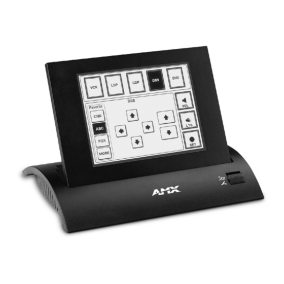
Product Information Product Information The Black/White touch panels contain an 8.5" (215.90 mm) black/white liquid crystal display (LCD). The self-contained enclosures use a microprocessor to control a wide range of multimedia equipment. The TPDesign3 touch panel design program makes it possible to create custom pages with buttons, icons, sliders, bargraphs, time displays, logos, and drawings. -
Page 6: Cleaning The Touch Overlay
Product Information AXD-LC (/PB) Specifications Dimensions (HWD) • Low profile Backbox: 7.50" x 11.25" x 1.77" (19.05 cm x 28.58 cm x 4.49 cm) • BB-TP2 Backbox: 7.50" x 11.25" x 2.44" (19.05 cm x 28.58 cm x 6.20 cm) Weight 4.5 lbs (2.04 kg) Power... -
Page 7: Installation
Installation Installation Mounting the Touch Panel The following paragraphs describe mounting the Decor and rack-mount touch panels. TiltScreen touch panels can be placed on any flat surface. Decor style panels with low-profile Backboxes 1. Cut out the surface using the dimensions shown in FIG. 1. FIG. - Page 8 Installation 7. Fasten the low-profile Backbox to the surface using the #6-32 machine screws supplied with the enclosure. 8. Attach the data and power wiring to the touch panel. 9. Test the connection by reconnecting the AXlink connector to the Central Controller and optional RS-232 wiring to the source equipment.
- Page 9 Installation FIG. 3 Decor style (AXD) and BB-TP2 cutout dimensions (solid surfaces) 5. Remove the BB-TP2 and drill holes (A and B) for the panel (FIG. 3). Then, place #6-32 threaded inserts into the four holes marked ‘B’ in the above cutout dimensions illustration. 6.
-
Page 10: Installing Touch Panels And A Bb-Tp2 Backbox (Plasterboard)
Installation 15. Reconnect the AXlink wiring to the Central Controller and RS-232 wiring (optional) to the external RS-232 device. The touch panel will beep on power-up. Installing touch panels and a BB-TP2 Backbox (plasterboard) FIG. 4 shows the AXD-LC/PB and BB-TP2 UniMount Backbox for plasterboard. BB-TP2 Unimount Knockout Backbox enclosure... -
Page 11: Rack-Mount Panel (Axm-Lc/Pb)
Installation 2. Carefully insert a flat-blade screwdriver into the release slot on the touch panel’s faceplate and remove the engraved overlay. 3. Lay the touch panel facedown on a soft cloth and remove the screws from the low-profile Backbox; remove the Backbox and discard. 4. -
Page 12: Wiring The Touch Panel
Installation Wiring the Touch Panel The touch panels use a 4-pin AXlink connector for power and data. If the distance between the panel and Central Controller exceeds power consumption limits, you must connect an optional 12 VDC power supply to the 2-pin PWR connector. The RS-232, AXlink, and PWR connectors are located at the rear of the AXT-LC (TiltScreen), as shown in FIG. -
Page 13: Using Axlink For Data And Power
Installation lengths for using AXlink power are based on a minimum of 13.5 VDC available at the Central Controller's power supply. Refer to the Specifications section on page 1 for more information on power requirements. Wiring Guidelines Wire Size Maximum Wiring Length 18 AWG 213.41 feet (65.05 m) 20 AWG... -
Page 14: Using The (Db-9) Rs-232 Connector For Mouse Control Or Data
Installation 2. Pair the GND wires from the power source and the Central Controller AXlink connectors together; insert them into the clamp position for GND on the touch panel AXlink connector. 3. Tighten the clamp and secure the two GND wires. Never connect both power wires from the power supply and Central Controller to the PWR terminal on the touch panel AXlink connector. -
Page 15: Designing Touch Panel Pages
Designing Touch Panel Pages Designing Touch Panel Pages There are two ways to approach creating touch panel pages: TPDesign3 - Refer to the TPDesign3 Touch Panel Program (Version 3. 16 or higher) Instruction Manual for more information. On-board editor This section describes the basics of using the on-board editor to create pages and buttons. For more information, refer to the G3 Firmware Design and Reference instruction manual. -
Page 16: Activating Edit Mode
Designing Touch Panel Pages General Button Categories (Cont.) Status buttons Status buttons always have a dark fill with light letters and have no functionality except to display information. Operation bars Operation bars appear in the place of the Editor bar, after selecting a button or page edit operation. - Page 17 Designing Touch Panel Pages FIG. 12 Setup page 4. Press to enable Edit mode. The button is highlighted in the Protected Setup EDITOR EDITOR page when enabled, as shown in FIG. 13. FIG. 13 Protected Setup page with the active EDITOR button 5.
-
Page 18: Setting The Device Base
Designing Touch Panel Pages Setting the Device Base Press the option, in the Protected Setup page (FIG. 13), to assign a base (starting) DEVICE BASE device address to the touch panel. 1. Enter the base address for the touch panel. The base address range is from 1 - 255. Standard device addresses begin at 128. -
Page 19: Defining On-Screen And External Button Properties
Designing Touch Panel Pages Defining On-Screen and External Button Properties External pushbuttons are configured with features similar to on-screen buttons. Their functionality can be set just as any other button on the touch panel. Use the option of the menu in the Edit bar to set button borders, page flips, PROPERTIES BUTTON button colors for channel on/off conditions, channel/variable text codes, and string/macro... -
Page 20: Setting The Variable Text Code
Designing Touch Panel Pages 5. Press to save the channel number, close the keypad, and return to the Button Properties ENTER page. Setting the variable text code The variable text buttons set the device and button channel codes for the buttons. 1. -
Page 21: Adding Text, Icons, And Bitmaps To A Button
Designing Touch Panel Pages Adding text, icons, and bitmaps to a button 1. Press on the Edit bar to open the menu. BUTTON BUTTON 2. Press to add text to the button. The operation bar appears. TEXT/IMAGE TEXT/IMAGE 3. Press any button to open the Text/Image page. 4. -
Page 22: Creating A Bargraph And Joystick
Designing Touch Panel Pages Creating a Bargraph and Joystick Bargraphs are level monitors and adjustable level controls. These levels can be configured to monitor and adjust audio outputs and lighting levels. Joysticks are vertical and horizontal direction controllers you can use for camera for pan and tilt control. -
Page 23: Programming
Programming Programming You can program the touch panel, using the commands in this section, to perform a wide variety of operations using Axcess Send_Commands and variable text commands. Use the commands described in this section to program the touch panel. Serial Commands Serial Commands are used in the AxcessX Terminal Emulator mode. - Page 24 Programming Serial Commands (Cont.) GET CAL Syntax: Gets the calibra- "GET CAL" tion variables. Example: GET CAL Gets the calibration variables on the touch panel. HELLO Syntax: Verifies that serial "HELLO" communication is Example: working properly. HELLO If the communication is active and working, the response is "How are you doing?". MOUSE Syntax: Turns on serial...
-
Page 25: System Send_Commands
Programming System Send_Commands System Send_Commands are stored in the Controller and direct the touch panel to perform various operations. System Send_Commands ABEEP Syntax: Outputs one panel "’ABEEP’" beep even if the Example: beep value is set SEND_COMMAND TP,"’ABEEP’" to 0 in the Setup page. - Page 26 Programming System Send_Commands (Cont.) BRIT Syntax: Adjusts brightness "’BRIT-<level>’" of display. Variable: level = 1 - 7 (1 = minimum; 7 = maximum) Example: SEND_COMMAND TP,"’BRIT-7’" Sets to highest brightness level. CONT Syntax: Adjusts brightness "’CONT-<level>’" of display. Variable: level = 1 - 15 (1 = minimum; 15 = maximum) Example: SEND_COMMAND TP,"’CONT-15’"...
- Page 27 Programming System Send_Commands (Cont.) ILEV Syntax: Inverts the joystick "’ILEV <joystick axis to invert>’" axis. Variables: joystick axis to invert = 0 : Normal G3 joystick (origin: top left) 1 : Invert horizontal axis (origin: top right) 2 : Invert vertical axis (origin: bottom left) 3 : Invert both axes (origin: bottom right) Example: SEND_COMMAND TP,"’ILEV 3’"...
- Page 28 Programming System Send_Commands (Cont.) PPON Syntax: Opens a specific "’PPON-<page name>’" popup page. Variable: page name = 1 - 50 ASCII characters Example: SEND_COMMAND TP,"’PPON-Popup Page 1’" Opens Popup Page 1. QBEEP Syntax: Stops all beeps. "’QBEEP’" Example: SEND_COMMAND TP,"’QBEEP’" Stops all beeps, including "’ABEEP’", "’ADBEEP’", and AXlink beeps.
- Page 29 TPAGEON Syntax: Activates page "’TPAGEON’" tracking. Example: SEND_COMMAND TP,’TPAGEON’ DEFINE_DEVICE TP1 = 128 (*AMX Touch Panel*) TP2 = 129 (*AMX Touch Panel*) DEFINE_VARIABLE TP1_BUFFER[100] (*Buffer for TP1*) TP2_BUFFER[100] (*Buffer for TP2*) TRASH[50] (*For Parsing Above*) DEFINE_START CREATE_BUFFER TP1,TP1_BUFFER CREATE_BUFFER TP2,TP2_BUFFER...
-
Page 30: Programming Numbers
Programming System Send_Commands (Cont.) WAKE Syntax: Deactivates "’WAKE’" screen-saver Example: mode and resets SEND_COMMAND TP,"’WAKE’" the sleep timer. Deactivates the touch panel screen-saver mode and resets the sleep timer. XMRT Syntax: Sets the new net- "’XMRT <number>’" work communica- Variable: tion retry value for number = 1 - 15 ASCII characters the panel and... -
Page 31: Shorthand Send Commands
Shorthand Send Commands The shorthand commands operate control equipment just like standard Send_Commands still used in a wide variety of AMX products. However, shorthand commands are smaller byte-for-byte, and are processed more efficiently. The table below lists the shorthand Send_Commands you can use with the LC touch panel. The shorthand command data is 1-byte, non-ASCII format except for pages, passwords, text, and bitmap names. - Page 32 Programming Shorthand Send_Commands (Cont.) @CBN This works only if the specified background color is not the same as the current color. Sets the ON feed- Syntax: back border color "’@CBN’,<variable text address>,<color_number>" to the specified Variables: color. variable text address = 1 - 255 color number = See the Colors and Programming Numbers table on page 26.
- Page 33 Programming Shorthand Send_Commands (Cont.) @CTF This only works if the specified background color is not the same as the current color. Sets the OFF Syntax: feedback text "’@CTF’,<variable text address>,<color_number>" color to the speci- Variables: fied color. variable text address = 1 – 255 color number = See the Colors and Programming Numbers table on page 26.
- Page 34 Programming Shorthand Send_Commands (Cont.) @PPA If no page is specified, the active page is used. Removes all Syntax: popup pages from "’@PPA-<page name>’" a specified page. Variable: page name = target touch panel page name Example: SEND_COMMAND TP,"’@PPA-Main Page’" If there were several popup pages on ’Main Page’ that are active, sending the previous command would remove them all from that page.
- Page 35 Programming Shorthand Send_Commands (Cont.) @PWD Syntax: Sets the password "’@PWD-<page flip password>’" for the Page Flip Variable: on the touch page flip password = 0 - 9999 panel. Example: SEND_COMMAND TP,"’@PWD-1988’" Sets the page flip password to 1988. @RDW Syntax: Redraws the cur- "’@RDW’"...
-
Page 36: Gray Scale/Color Send_Commands
Programming Gray Scale/Color Send_Commands Use the color Send_Commands to set the colors for text, buttons, and pages. Use the same command for setting gray scale values only change the color number value to reflect the gray scale (72-86) value. Color Send_Commands CBOFF Syntax: Sets the OFF... - Page 37 Programming Color Send_Commands (Cont.) CBON Syntax: Sets the ON feed- "’CBON<variable text address>-<color _number>’" back border color Variables: to the specified variable text address = 1 - 255 color. color number = See the Colors and Programming Numbers table on page 26. Example: SEND_COMMAND TP,"’CBON1-87’"...
-
Page 38: Variable Text Send_Commands
Programming Color Send_Commands (Cont.) CTON Syntax: Sets the ON feed- "’CTON<variable text address>-<color_number>’" back text color to Variables: the specified variable text address = 1 - 255 color. color number = See the Colors and Programming Numbers table on page 26. Example: SEND_COMMAND TP,"’CTON1-72’"... - Page 39 Programming Variable Text Send_Commands (Cont.) Syntax: Sets the border, "’!C’,<variable text address>,<border style>,<font font, and text in size>,’<new button text>’" one command. Variables: variable text address = 1 - 255 border style = See the Border Styles and Programming Numbers table on page 27. font size = See the Font Styles and Programming Numbers table on page 27.
- Page 40 Programming Variable Text Send_Commands (Cont.) ICON Syntax: "’ICON<variable text address>-<border style>’" Changes the bor- der style of a spe- Variables: cific button. variable text address = 1 - 255 border style = See the Border Styles and Programming Numbers table on page 27. Example: SEND_COMMAND TP,"’ICON25-6’"...
-
Page 41: Shorthand Variable Text Commands
Programming Shorthand Variable Text Commands The table below lists the shorthand variable text commands you can use with the touch panel. The shorthand command data is one-byte, non-ASCII format except for pages, passwords, text, and bitmap names. Shorthand Variable Text Commands @BMF This command allows you to program up to 12 attributes on one command line. - Page 42 Programming Shorthand Variable Text Commands (Cont.) @BOR Syntax: Sets the border "’@BOR’,<variable text address>,<border style>" style on a button. Variables: variable text address = 1 - 255 border style = See the Border Styles and Programming Numbers table on page 27. Example: SEND_COMMAND TP,"’@BOR’,65,11"...
- Page 43 Programming Shorthand Variable Text Commands (Cont.) @JUS Syntax: Sets the text "’@JUS’,<variable text address>,<text alignment>" alignment on a Variables: button. variable text address = 1 - 255 text alignment = 1 - 9 as shown in the following alignment chart: Example: SEND_COMMAND TP,"’@JUS’,9,5"...
-
Page 44: Button String Commands
Programming Button String Commands The table below lists string commands you can assign to buttons by using the touch panel editor. Select the PROPERTIES option in the Edit bar, press the target button, and enter the string command with the Touch Panel keyboard.The string command is sent to the control system when you press the button. -
Page 45: Upgrading The Firmware
Upgrading the Firmware Upgrading the Firmware In order to upgrade the firmware in the panel, you can either return the panel to AMX or replace the necessary EPROM chips yourself. Standard memory on the G3 boards for the LC series of touch panels is 256 KB of base memory. -
Page 46: Axm-Lc (/Pb) And Axd-Lc (/Pb) Eprom Replacement
Upgrading the Firmware Insert the EPROMs with the notches facing the correct direction. Match the Even and Odd EPROM placement with the location shown above. During the replacement process, cables may be pulled from their connections and should be re-checked to confirm they are securely connected. 8. - Page 47 Upgrading the Firmware JP2 JP1 JP3 32-pin sockets EPROM Odd and Even FIG. 17 EPROM location on a mounted touch panel Insert the EPROMs with the notches facing the correct direction. Match the Even and Odd EPROM placement with the location shown above. During the replacement process, cables may be pulled from their connections and should be re-checked to confirm they are securely connected.
- Page 48 Upgrading the Firmware 8.5" Black and White Touch Panels...
-
Page 49: Replacing The Batteries
Replacing the Batteries Replacing the Batteries There are two lithium batteries on the touch panel card, with a life of approximately 2.5 years. They protect stored commands and pages against a power outage. The batteries are not used when DC power is supplied to the touch panel. -
Page 50: Axm-Lc (/Pb) And Axd-Lc (/Pb) Battery Replacement
Replacing the Batteries 8. Plug the two-pin power or AXlink connector back into the touch panel for approximately 1 minute. Then, remove connector from the panel again. 9. Gently tilt the circuit card down towards the connector side and pull backwards until you clear the connector housing. - Page 51 Replacing the Batteries 8.5" Black and White Touch Panels...
- Page 52 AMX reserves the right to alter specifications without notice at any time. brussels • dallas • los angeles • mexico city • philadelphia • shanghai • singapore • tampa • toronto* • york 3000 research drive, richardson, TX 75082 USA • 469.624.8000 • 800.222.0193 • fax 469.624.7153 • technical support 800.932.6993...
Need help?
Do you have a question about the 8.5" Black/White LCD and is the answer not in the manual?
Questions and answers