
Related Manuals for Agilent Technologies E1326B


Summary of Contents for Agilent Technologies E1326B
- Page 1 Agilent E1326B/E1411B 5 1/2 Digit Multimeter User’s Manual E1326-90009 Printed in USA July 2004 E0704 *E1326-90009*...
-
Page 2: Table Of Contents
VXIbus Interrupt Lines ....... . 24 HP E1326B Internal Installation ......25 Installing the HP E1411B in a Mainframe . - Page 3 Making an Externally Triggered Scan ......49 Scanning Switchbox Channels (E1326B/E1351A) ....50 Scanning Switchbox Channels (E1411B/E1460A) .
- Page 4 How to Save and Recall a Configuration ..... . . 114 Chapter 5. HP E1326B/E1411B Multimeter Command Reference ... . . 117 Using This Chapter .
- Page 5 :COUNt ........179 Contents HP E1326B/E1411B 5 1/2 Digit Multimeter User’s Manual...
- Page 6 Command Quick Reference ....... . 187 Appendix A. HP E1326B/E1411B Multimeter Specifications ....189 General Specifications .
- Page 7 Index ..........279 Contents HP E1326B/E1411B 5 1/2 Digit Multimeter User’s Manual...
-
Page 8: Warranty
Software and Documentation by the applicable FAR or DFARS clause or the HP standard software agreement for the product involved. E1326B/E1411B 5 1/2-Digit Multimeter User’s Manual E1326-90009 Copyright © 2004 Agilent Technologies, All Rights Reserved. HP E1326B/E1411B 5 1/2-Digit Multimeter User’s Manual... -
Page 9: Warnings
DO NOT substitute parts or modify equipment: Because of the danger of introducing additional hazards, do not install substitute parts or perform any unauthorized modification to the product. Return the product to a Hewlett-Packard Sales and Service Office for service and repair to ensure that safety features are maintained. HP E1326B/E1411B 5 1/2-Digit Multimeter User’s Manual... -
Page 10: Declaration Of Conformity
September 5, 2000 Date Name Quality Manager Title For further information, please contact your local Agilent Technologies sales office, agent or distributor. Authorized EU-representative: Agilent Technologies Deutschland GmbH, Herrenberger Stra e 130, D 71034 Böblingen, Germany Revision: A.03 Issue Date: 09/05/00... - Page 11 September 5, 2000 Date Name Quality Manager Title For further information, please contact your local Agilent Technologies sales office, agent or distributor. Authorized EU-representative: Agilent Technologies Deutschland GmbH, Herrenberger Stra e 130, D 71034 Böblingen, Germany Revision: A.03 Issue Date: 09/05/00...
-
Page 12: Chapter 1. Getting Started With The Hp E1326B/E1411B Multimeter
Introduction to Operation......Page 16 Note This manual is to be used with the HP E1326B or HP E1411B installed in the HP 75000 Series B or Series C mainframe, and when the multimeter is programmed using Standard Commands for Programmable Instruments (SCPI) language or when it is programmed at the register level. -
Page 13: Functional Description
Electrical The electrical performance of the multimeter is summarized in Table 1-1. Refer to Appendix A for a complete table of specifications. Description 14 Getting Started with the HP E1326B/E1411B Multimeter Chapter 1... -
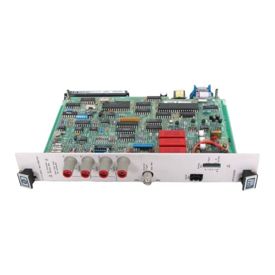
Page 14: Physical Description
A high-to-low TTL pulse applied to the External Trigger port externally triggers the multimeter. The Analog Bus and Digital Bus ports allow relay and FET multiplexers to be connected to the multimeter. Chapter 1 Getting Started with the HP E1326B/E1411B Multimeter 15... -
Page 15: Introduction To Operation
! Enter and display the self-test code. ENTER 70903;A PRINT A ! Reset the multimeter. OUTPUT 70903;"*RST" After the test passes, always reset the multimeter to return it to a known state. 16 Getting Started with the HP E1326B/E1411B Multimeter Chapter 1... -
Page 16: Resetting The Multimeter
If the multimeter is busy due to a command sent from the computer, you must clear the multimeter before sending the reset. The reset sets the multimeter’s power-on configuration. Chapter 1 Getting Started with the HP E1326B/E1411B Multimeter 17... - Page 17 16.7 ms or 20 ms (based on line frequency) RESistance:APERture 16.7 ms or 20 ms (based on line frequency) CALibration:LFRequency Unchanged (factory setting = 60 Hz) VOLTage:NPLC RESistance:NPLC RESistance:OCOMpensated OFF CALibration:ZERO:AUTO TRIGger:COUNt TRIGger:DELay:AUTO TRIGger:SOURce SAMPle:COUNt SAMPle:SOURce 18 Getting Started with the HP E1326B/E1411B Multimeter Chapter 1...
- Page 18 ! Declare a string variable in the computer to store the error message. DIM Message$[256] ! Read the error queue until no errors remain. ! Print the error codes and messages. REPEAT OUTPUT 70903;"SYST:ERR?" ENTER 70903;Code,Message$ PRINT Code,Message$ UNTIL Code=0 Chapter 1 Getting Started with the HP E1326B/E1411B Multimeter 19...
-
Page 19: Making A Measurement
Note Appendix B contains a list of error messages associated with the multimeter and their causes. Making a The HP E1326B/E1411B multimeter can be configured and make measurements using the command. The following examples MEASure Measurement show how it is used with the stand-alone and scanning multimeters. -
Page 20: Chapter 2. Configuring The Hp E1326B/E1411B Multimeter
(see Appendix C). This section shows the location of the multimeter’s logical address switch and shows how it is set. It also mentions considerations when installing the multimeter in the mainframe. Chapter 2 Configuring the HP E1326B/E1411B Multimeter... -
Page 21: Setting The Logical Address Switch
HP-IB address of 03. If you have more than one multimeter, you must change the logical address to some other multiple of 8 (for example, 32, 40, 48...), as there can only be one instrument per secondary address. Figure 2-1. HP E1326/1411 Logical Address Switch Settings Configuring the HP E1326B/E1411B Multimeter Chapter 2... - Page 22 The scanning multimeter can consist of relay multiplexers, FET multiplexers, or a combination of both. See “Connecting Multiplexers” on page 30 for information on physically connecting the multiplexers to the multimeter. Figure 2-2. Setting Successive Logical Addresses to Form an Instrument Chapter 2 Configuring the HP E1326B/E1411B Multimeter...
-
Page 23: Vxibus Interrupt Lines
1 (internal on the Series B mainframe) has a higher priority than slot 2 (also internal), slot 2 has a higher priority than slot 3, and so on. HP E1326B HP E1411B Interrupt Jumper Location Interrupt Jumper Location Figure 2-3. Interrupt Jumper Locations Configuring the HP E1326B/E1411B Multimeter Chapter 2... -
Page 24: Hp E1326B Internal Installation
This prevents another module from being installed in the slot directly above the multimeter. To make the two slots available to other modules, the HP E1326B can be installed internal to the mainframe (in slot 2) using an internal installation kit (HP P/N E1326-80004). -
Page 25: Installing The Hp E1411B In A Mainframe
Tighten the top and bottom screws to secure the multimeter to the mainframe. To remove the multimeter from the mainframe, reverse the procedure. Figure 2-5. Installing the HP E1411B Multimeter in a VXIbus Mainframe Configuring the HP E1326B/E1411B Multimeter Chapter 2... -
Page 26: The Reference Frequency
Frequency type of noise emanates from the surrounding environment, primarily from 50 Hz and 60 Hz power lines. The HP E1326B/E1411B multimeter is able to reject normal mode noise by using an integrating analog-to-digital (A/D) converter. The integration process averages out the power line related noise over an integer number of power line cycles (PLCs) during the A/D conversion. -
Page 27: Input Characteristics
HI and COM is the same as the impedance between LO and COM (see Figure 2-6). The only difference between the HI and LO terminals is the polarity. Figure 2-6. A Floating, Balanced Differential Multimeter Configuring the HP E1326B/E1411B Multimeter Chapter 2... -
Page 28: Input Terminals
For example, if an HP E1343A and E1351A are connected to the same multimeter, then the system rating is that of the E1351A, which is 14 V. Figure 2-7. HP E1326B/E1411B Input Terminals Chapter 2 Configuring the HP E1326B/E1411B Multimeter... -
Page 29: Connecting Multiplexers
3. If the scanning multimeter uses a combination of relay and FET multiplexers, only the analog bus cable is used. Figure 2-8 shows how the analog and digital bus cables are connected. Figure 2-8. Connecting the Analog and Digital Bus Cables Configuring the HP E1326B/E1411B Multimeter Chapter 2... - Page 30 Complete line. This signal advances the scan to the next channel in the list. When the channel is closed, the channel closed signal triggers the multimeter and the process repeats. Figure 2-10. Digital Bus Overview Chapter 2 Configuring the HP E1326B/E1411B Multimeter...
-
Page 31: Connecting Input Signals
The HI, LO, COM, HI terminals on the multimeter faceplate are internally connected to the analog bus port. Thus, signals on the analog bus (from a multiplexer) appear on the faceplate terminals and vice versa. Figure 2-11. Connecting the COM Lead Configuring the HP E1326B/E1411B Multimeter Chapter 2... -
Page 32: Measurement Connections
Measurement Connections E1345A/47A/51A/53A E1352A E1346A E1460A Figure 2-12. Connections for DC and AC Voltage Measurements Chapter 2 Configuring the HP E1326B/E1411B Multimeter... - Page 33 Figure 2-13. Connections for 2-Wire Resistance Measurements (Including Thermistors and RTDs) Note 2-wire resistance measurements require the multiplexer modules shown above. Resistance measurements using the multimeter terminals or directly through the analog bus must be configured as 4-wire measurements. Configuring the HP E1326B/E1411B Multimeter Chapter 2...
- Page 34 E1460A E1345A/47A/51A/53A NOTE: Channel Pairs are banks 0/4, 1/5, 2/6, and 3/7. See Chapter 2 of the HP E1460A User’s Manual Figure 2-14. Connections for 4-Wire Resistance Measurements (Including Thermistors and RTDs) Chapter 2 Configuring the HP E1326B/E1411B Multimeter...
- Page 35 E1476A E1344A/47A/53A Figure 2-15. Connections for Thermocouples Configuring the HP E1326B/E1411B Multimeter Chapter 2...
-
Page 36: Carrier Cable Assemblies
2. The HP E1400-61605 analog bus cable ships with the HP E1345A/46A/47A/55A and 56A relay multiplexers. The HP E1400-61605 analog bus cable and HP E1400-61601 digital bus cable ship with the HP E1351A/52A/53A/57A/58A FET multiplexers. Chapter 2 Configuring the HP E1326B/E1411B Multimeter... - Page 37 Figure 2-16. Cables for B-Size Multiplexers in HP E1403B Adapter Configuring the HP E1326B/E1411B Multimeter Chapter 2...
-
Page 38: Additional Configurations
A size slot B size slot Disabling When using the HP E1326B Multimeter as a stand-alone instrument, the HP E1301A front-panel keyboard can be disabled without disabling the Front-panel for display. To disable the front-panel keyboard, use the following guidelines:... - Page 39 Notes Configuring the HP E1326B/E1411B Multimeter Chapter 2...
-
Page 40: Chapter 3. Using The Hp E1326B/E1411B Multimeter
Making an Externally Triggered Scan....Page 49 Scanning Switchbox Channels (E1326B/1351A) ..Page 50 Scanning Switchbox Channels (E1411B/1460A..Page 52 Multiple High-Speed Scans . -
Page 41: Making A Single Measurement
MEASure command are required. Recall from Chapter 1 that the HP E1326B/E1411B can function stand-alone, or with multiplexers as a scanning multimeter instrument. When programming, the stand-alone multimeter and scanning multimeter are distinguished by the absence or presence of the... -
Page 42: Making A Burst Of Measurements
Each reading stored will consume four bytes of memory. A burst of measurements (set by ) can also be made SAMPle:COUNt when scanning a single channel. Chapter 3 Using the HP E1326B/E1411B Multimeter... -
Page 43: Making An Externally Triggered Burst Of Measurements
Up to 16,777,215 measurements can be specified with SAMPle:COUNt The multimeter output buffer can hold eight readings. When the buffer fills, measurements are suspended until readings are read from the buffer (by the computer) to make space available. Using the HP E1326B/E1411B Multimeter Chapter 3... -
Page 44: Making Multiple Burst Measurements
In this program, the multimeter responds to three internal triggers. sets the CONFigure trigger count to 1. The command is used to set up TRIGger:COUNt to 16,777,215 counts. Chapter 3 Using the HP E1326B/E1411B Multimeter... -
Page 45: Scanning A Channel List
PRINT Rdgs( NEXT Comments The multimeter output buffer can hold eight readings. When the buffer fills, measurements are suspended until readings are read from the buffer (by the computer) to make space available. Using the HP E1326B/E1411B Multimeter Chapter 3... -
Page 46: Making Multiple Scans
SAMPle:COUNt command. The multimeter output buffer can hold eight readings. When the buffer fills, measurements are suspended until readings are read from the buffer (by the computer) to make space available. Chapter 3 Using the HP E1326B/E1411B Multimeter... -
Page 47: Making Multiple Paced Scans
, the readings are stored in mainframe memory. FETCH? retrieves the readings and places them in the output buffer once all measurements are taken. Replacing INIT with returns the readings directly to the output FETCH? READ? buffer. Using the HP E1326B/E1411B Multimeter Chapter 3... -
Page 48: Making An Externally Triggered Scan
- immediate (internal) trigger - external trigger - triggered by or HP-IB group execute trigger *TRG HOLD - suspend trigger If programmed for multiple scans, multiple external triggers must occur since each scan requires a trigger. Chapter 3 Using the HP E1326B/E1411B Multimeter... -
Page 49: Scanning Switchbox Channels (E1326B/E1351A)
! Dimension a controller array to store the readings. DIM Rdgs(1:500) ! Reset the E1326B multimeter and the E1351A FET switchbox. Turn the ! multimeter monitor mode off to increase throughput. OUTPUT 70903;"*RST"... - Page 50 ). Thus, the multimeter ignores the multiplexer "channel closed" signal on the digital bus. Using this configuration, the multimeter is able to continuously scan the switchbox and store readings in its memory at a 76 s (13 kHz) rate. Chapter 3 Using the HP E1326B/E1411B Multimeter...
-
Page 51: Scanning Switchbox Channels (E1411B/E1460A)
OUTPUT 70914;"SCAN:PORT ABUS" OUTPUT 70914;"SCAN (@100:177)" OUTPUT 70914;"*OPC?" ENTER 70914;Complete ! Start the scan and the measurements by closing the first multiplexer ! channel in the channel list. OUTPUT 70914;"INIT" Continued on Next Page Using the HP E1326B/E1411B Multimeter Chapter 3... - Page 52 64 channels (@100:177) Additional information on triggering the multimeter is found in Chapters 4 and 5. Information on the multimeter’s OUTPut subsystem is contained in Chapter 5. Chapter 3 Using the HP E1326B/E1411B Multimeter...
-
Page 53: Multiple High-Speed Scans
Multiple High-Speed Scans This example shows how a scanning multimeter consisting of the HP E1326B multimeter and HP E1351A FET multiplexer is programmed for multiple scans at a 13 kHz rate. The program scans 16 channels 100 times. ! Dimension a controller array to store the readings. - Page 54 The maximum number of continuous scans and measurements depends on the amount of multimeter memory available. Detailed information on the FET multiplexer registers can be found in the register-based programming section of the multiplexer user’s manual. Chapter 3 Using the HP E1326B/E1411B Multimeter...
-
Page 55: Maximizing Measurement Speed
= 10 s autozero = off sample rate = 76 s (MINimum) reading storage = mainframe (or shared) memory In addition, there should be no activity by other instruments in the mainframe. Using the HP E1326B/E1411B Multimeter Chapter 3... - Page 56 32 k. Setting the to 78 s SAMP:TIM gives a reading rate of 12.82 kHz and allows the sample count to be greater than 32 k. CONF:VOLT:DC 7.27,MAX CAL:ZERO:AUTO OFF SAMP:SOUR TIM SAMP:TIM 0.078 INIT Chapter 3 Using the HP E1326B/E1411B Multimeter...
-
Page 57: Changing The Data Format
<block length>. In this program, the header preceding the measurement data is #48000. The 4 represents the number of digits indicating the block length (8000), and 8000 is the block length (1,000 readings * 8 bytes/reading). Using the HP E1326B/E1411B Multimeter Chapter 3... - Page 58 If the LF character is not removed, Error -410 "Query Interrupted" occurs the next time data is sent to the buffer. This (third) ENTER statement is only required when using the REAL data formats. Chapter 3 Using the HP E1326B/E1411B Multimeter...
-
Page 59: Using A Pc, C Language, And The Hp 82335 Hp-Ib Interface Card
HP E1301A mainframe with an HP E1326B multimeter and four HP E1351A FET multiplexers. /* BENCHMK.C - This is a benchmark program for the E1326B. The program */ /* scans 50 FET multiplexer channels 40 times, and repeats the sequence */ /* 4 times. - Page 60 /* remove line feed which trails the last data byte */ length = 1; IOENTERS(ADDR, lf_remove, &length); /* compare each reading to a set of limits */ for (j = 0; j 50; j++) Continued on Next Page Chapter 3 Using the HP E1326B/E1411B Multimeter...
- Page 61 (atoi(into) != 0) /* Determine if error is present If errors present, print and exit */ while (atoi(into) != 0) printf("Error %s in function %s\n\n", into, func_tion); IOOUTPUTS(ADDR, "SYST:ERR?", 9); IOENTERS(ADDR, into, &length); exit(1); Using the HP E1326B/E1411B Multimeter Chapter 3...
-
Page 62: Maximizing Measurement Accuracy
This eliminates the need to look up specific numbers in the manual. CONFigure turns autozero on. When making resistance measurements (including thermistors and RTDs), accuracy can often be increased by turning on offset compensation (for example, RESistance:OCOMpensated Chapter 3 Using the HP E1326B/E1411B Multimeter... -
Page 63: Storing Readings In Shared Memory
CAL:ZERO:AUTO OFF" OUTPUT 70903;" VOLT:APER MIN" OUTPUT 70903;" SAMP:COUN 200000" OUTPUT 70903;" SAMP:SOUR TIM" OUTPUT 70903;" SAMP:TIM MIN" OUTPUT 70903;"INIT" OUTPUT 70903;"FETC?" ! Enter the readings. ENTER 70903 USING "#,X,K,K";Ndig$;Count$[1;VAL(Ndig$)] ENTER @Dmm;Rdgs(*) ENTER 70903;Lf$ Using the HP E1326B/E1411B Multimeter Chapter 3... - Page 64 Arbitrary Block format and additional format information is located in Chapter 4. When running HP BASIC, an array dimension can have no more than 32767 elements. Thus, to store 200,000 readings, a two-dimensional array is declared. Chapter 3 Using the HP E1326B/E1411B Multimeter...
-
Page 65: Checking For Errors
! Read all error messages in the multimeter error queue. Clear all bits in ! the multimeter Standard Event Status Register. SUB Errmsg DIM Message$[256] CLEAR 70903 B=SPOLL(70903) REPEAT OUTPUT 70903;"SYST:ERR?" ENTER 70903;Code,Message$ PRINT Code,Message$ UNTIL Code=0 OUTPUT 70903;"*CLS" STOP SUBEND Using the HP E1326B/E1411B Multimeter Chapter 3... - Page 66 However, an overload does not generate an error message so 0 "No Error" is displayed. The B-size VXIbus Mainframe User’s Manual contains detailed information on the Status and Standard Event Status Registers. Chapter 3 Using the HP E1326B/E1411B Multimeter...
-
Page 67: Synchronizing The Multimeter With A Computer
Only the data from one command can be in the output buffer or in mainframe memory. Synchronizing the computer with the multimeter in this manner ensures the data is entered into the computer before it is overwritten by data from another command. Using the HP E1326B/E1411B Multimeter Chapter 3... -
Page 68: Additional Measurement Functions
! 2-wire resistance. OUTPUT 70903;"MEAS:RES? (@channel_list)" ! 4-wire resistance (channels available are 00 through 07). OUTPUT 70903;"MEAS:FRES? (@channel_list)" ! Thermocouple (type = B, E, J, K, N14, N28, R, S, T). OUTPUT 70903;"MEAS:TEMP? TC,type,(@channel_list)" Chapter 3 Using the HP E1326B/E1411B Multimeter... - Page 69 ! Channels available are 00 through 07. OUTPUT 70903;"CONF:TEMP FRTD,type,(@channel_list)" Note The HP E1326B/E1411B multimeter also makes strain gage measurements. Refer to the HP E1355A - E1358A Strain Gage Multiplexers User’s Manual for example programs. Using the HP E1326B/E1411B Multimeter...
- Page 70 This is an example of how to setup scanning when using an HP E1345A Using the HP E1345A multiplexer configured as a switchbox and the HP E1326B multimeter used with no multiplexers assigned to it. The two subprograms used in this Multiplexer example are Scan_100 sec and Scan_10 sec.
- Page 71 ! Get readings. Start=TIMEDATE OUTPUT @Sw;"INIT" OUTPUT @Dvm;"FETCH?" ENTER @Dvm;Readings(*) Stop=TIMEDATE PRINT "Scan Rate with Multimeter Aperture at 100us ";16/(Stop-Start) SUBEND ! Subprogram Scan_10 s. SUB Scan_10us COM @Sys,@Dvm,@Sw DIM Readings(0:15) Continued on Next Page Using the HP E1326B/E1411B Multimeter Chapter 3...
- Page 72 Scan Rate with Multimeter Aperture at 100 s: 123.072300469 Scan Rate with Multimeter Aperture at 10 s: 4.48178352225 Checking for E13xx Errors at the end of the program: DVM ERROR: "No error" SYSTEM ERROR: "No error" SWITCH ERROR: "No error" Chapter 3 Using the HP E1326B/E1411B Multimeter...
- Page 73 Notes Using the HP E1326B/E1411B Multimeter Chapter 3...
-
Page 74: Chapter 4. Understanding The Hp E1326B/E1411B Multimeter
Saving Multimeter Configurations ....Page 114 Note Throughout this chapter, the HP E1326B/E1411B multimeter is referred to as a "scanning multimeter" or a "stand-alone multimeter". -
Page 75: Using Measure And Configure Commands
Note If a channel list is the only parameter specified in the MEASure command, it must be separated from the command header by a CONFigure space, rather than a comma (e.g. MEAS:VOLT:DC? (@100) Understanding the HP E1326B/E1411B Multimeter Chapter 4... - Page 76 0.5 seconds for AC voltage. SAMPle:COUNt Readings per Trigger ; number of measurements taken when trigger is received. SAMPle:SOURce Sample Period ; period between measurements or the period between FET multiplexer scans. Chapter 4 Understanding the HP E1326B/E1411B Multimeter...
-
Page 77: How To Make Measurements
TRIGger:COUNt 1 By setting the configuration with , the low-level commands CONFigure can be used to turn offset RESistance:OCOMpensated TRIGger:COUNt compensation and set the desired number of scans: CONF:FRES 1861,MAX,(@100:103) RES:OCOM ON TRIG:COUN 3 Understanding the HP E1326B/E1411B Multimeter Chapter 4... - Page 78 CONFigure READ? INIT commands will place the multimeter in the wait-for-trigger state; however, a measurement will not be made until a trigger from the specified source occurs. Chapter 4 Understanding the HP E1326B/E1411B Multimeter...
-
Page 79: Data Formats And Destinations
Data Formats and Destinations The HP E1326B/E1411B multimeter allows you to specify the measurement (data) format and reading destination parameters which affect throughput speed. This section identifies the formats available and shows you how to display and store measurements. Data Formats The multimeter data formats are selected with the command: FORMat[:DATA] <... -
Page 80: Reading Destinations
? ... READ? the readings are available to the computer via the output buffer. The following examples show how data (ASCII format) is entered into an HP 9000 Series 200/300 computer using HP BASIC. Chapter 4 Understanding the HP E1326B/E1411B Multimeter... - Page 81 2. Data is stored in mainframe and shared memory by executing the command. INIT 3. Reading rates are increased when the readings are stored in mainframe memory. Storing readings in memory also ensures that the sample rate is maintained at a constant value. Understanding the HP E1326B/E1411B Multimeter Chapter 4...
- Page 82 Retrieving Data From Data stored in mainframe memory is retrieved using: Mainframe Memory FETCh? Once the data is fetched, it is available to the computer via the output buffer. Refer to the next example. Chapter 4 Understanding the HP E1326B/E1411B Multimeter...
- Page 83 MEMory:VME:ADDRess < > MEMory:VME:SIZE < bytes > mode MEMory:VME:STATe < > Chapter 3 contains an example on storing readings in shared memory. command is covered in Chapter 5. MEMory Understanding the HP E1326B/E1411B Multimeter Chapter 4...
-
Page 84: Reading Destination Summary
Select the E1326B multimeter. Send command "SAMP:COUNt " (where nnn is the number of readings). Look for an "OUT OF MEMORY" error message (if the message is NOT generated, then nnn readings can be stored). Chapter 4 Understanding the HP E1326B/E1411B Multimeter... -
Page 85: Measurement Functions
Measurement Functions The HP E1326B/E1411B multimeter can make the following measurements: DC Voltage – RMS AC Voltage – 2-Wire Resistance – 4-Wire Resistance – Temperature – Note The HP E1326B/E1411B multimeter also makes bridge, bridge, and full bridge strain measurements. Refer to the HP E1355A - E1358A Strain Gage Multiplexer User’s Manual for descriptions of these functions. -
Page 86: Resistance Measurements
This is a 4-wire configuration and the measurement must be specified accordingly. Only 4-wire measurements can be made with the stand-alone multimeter. Two-wire and 4-wire measurements can be made with the scanning multimeter. Chapter 4 Understanding the HP E1326B/E1411B Multimeter... -
Page 87: Temperature Measurements
Omega 440xx series temperature response curves. Thermistor measurements can be made in either a 2-wire or 4-wire configuration. Two-wire measurements require the scanning multimeter. Two-wire thermistor measurements are specified as: type TEMP THERmistor, Understanding the HP E1326B/E1411B Multimeter Chapter 4... - Page 88 RTD measurements can be made in either a 2-wire or 4-wire configuration. Two-wire measurements require the scanning multimeter. Two-wire RTD measurements are specified as: type TEMP RTD, The function appears in the commands as: MEASure CONFigure MEAS:TEMP? RTD, type ,(@channel_list) type CONF:TEMP RTD, ,(@channel_list) Chapter 4 Understanding the HP E1326B/E1411B Multimeter...
-
Page 89: Specifying A Function
The stand-alone multimeter functions which can be changed are: VOLT:DC VOLT:AC FRESistance The next example shows you how to change from a DC voltage measurement to a 4-wire resistance measurement. Understanding the HP E1326B/E1411B Multimeter Chapter 4... -
Page 90: Multimeter Parameters
These parameters include: range – resolution – aperture and integration time – autozero – offset compensation – This section describes these parameters. The settings are summarized in Table 4-5 on page 92. Chapter 4 Understanding the HP E1326B/E1411B Multimeter... - Page 91 ** Reading rates are approximate and are achieved using a stand-alone multimeter, DC voltage function, fixed range, autozero off, offset compensation off, reading stored in mainframe/command module memory. See Table 4-6 on page 110 for the necessary sample rates. Understanding the HP E1326B/E1411B Multimeter Chapter 4...
-
Page 92: Range
If no range parameter is specified in the command, MEASure CONFigure autorange is set. However, to specify a resolution while autoranging, must be explicitly specified. This prevents the AUTO resolution from being interpreted as a range setting. Chapter 4 Understanding the HP E1326B/E1411B Multimeter... -
Page 93: Autorange
If autoranging is enabled but does not occur, approximately 100 s is added to the fixed range measurement time. The E1326B/E1411B automatically switches to the 10 s aperture time when making measurements to determine the correct range. 2. For maximum speed, group channels together which use the same range. -
Page 94: Resolution
3. Setting the resolution also sets the aperture time and integration time. Of these three parameters, the settings of the other two are based on the one most recently set. Chapter 4 Understanding the HP E1326B/E1411B Multimeter... - Page 95 The resolution is queried with the following commands. See Chapter 5 for Resolution additional information. VOLTage:RESolution? VOLTage:RESolution? MIN | MAX RESistance:RESolution? RESistance:RESolution? MIN | MAX Executing returns the resolution, range, and measurement CONFigure? function set by the CONFigure command. Understanding the HP E1326B/E1411B Multimeter Chapter 4...
-
Page 96: Aperture And Integration Time
Integration Time integration time is expressed in power line cycles. Integrating multimeters, like the E1326B, may be programmed to integrate an integer number of power line cycles (PLC). These have a common mode rejection ratio. The common mode rejection ratio is increased by the normal mode rejection ratio. - Page 97 The aperture and integration times are queried with the following and Integration Time commands. See Chapter 5 for additional information. VOLTage:APERture? VOLTage:APERture? MIN | MAX RESistance:APERture? RESistance:APERture? MIN | MAX VOLTage:NPLC? VOLTage:NPLC? MIN | MAX RESistance:NPLC? RESistance:NPLC? MIN | MAX Understanding the HP E1326B/E1411B Multimeter Chapter 4...
-
Page 98: Autozero
ONCE - of the input signal. The offset is then subtracted from all subsequent measurements. Querying the Autozero The autozero mode is queried with the CALibration:ZERO:AUTO? Mode command. See Chapter 5 for additional information. Chapter 4 Understanding the HP E1326B/E1411B Multimeter... -
Page 99: Offset Compensation
(thermocouple junctions at wiring points, for example). 5. Offset compensation ( ) overrides autozero; however, if both OCOM are on, the reading rate reflects the autozero state. Understanding the HP E1326B/E1411B Multimeter Chapter 4... -
Page 100: Triggering The Multimeter
See Chapter 5 for additional information. Triggering the Multimeter The E1326B/E1411B multimeter operates in an idle state, a wait-for-trigger state, and a triggered state. Configuration of the multimeter and its trigger system occurs while the multimeter is in the idle state. When the multimeter is ready to make a measurement, it is placed in the wait-for-trigger state. - Page 101 Figure 4-1. The Multimeter Trigger System Understanding the HP E1326B/E1411B Multimeter Chapter 4...
-
Page 102: The Trigger Source
TTLTrg0 - TTLTrg7 These trigger sources are available with the HP E1411B multimeter only. Querying the Trigger The trigger source is queried with the command. See TRIGger:SOURce? Source Chapter 5 for additional information. Chapter 4 Understanding the HP E1326B/E1411B Multimeter... -
Page 103: The Trigger Count
However, READ? can be executed to return the readings to the output buffer. The next two examples show how is used in the TRIGger:COUNt stand-alone and scanning multimeter configurations. Understanding the HP E1326B/E1411B Multimeter Chapter 4... - Page 104 ! Place the multimeter in the wait-for-trigger state. CONF:VOLT:DC (@100:104) TRIG:COUN 5 READ? Querying the Trigger The trigger count setting is queried with the TRIGger:COUNt? Count commands. See Chapter 5 for additional TRIGger:COUNt? MIN | MAX information. Chapter 4 Understanding the HP E1326B/E1411B Multimeter...
-
Page 105: The Trigger Delay
AC voltage measurements, change the function to AC voltage first, and then set the delay. MEASure CONFigure TRIGger:DELay:AUTO ON turns off. Specifying a trigger delay TRIGger:DELay:AUTO automatically turns off. TRIG:DEL:AUTO Understanding the HP E1326B/E1411B Multimeter Chapter 4... - Page 106 ! Make a scan every 10 seconds . CONF:VOLT:DC (@100:104) TRIG:COUN 5 TRIG:DEL 10 READ? Querying the Trigger The trigger delay setting is queried with the TRIGger:DELay? Delay commands. See Chapter 5 for additional TRIGger:DELay? MIN | MAX information. Chapter 4 Understanding the HP E1326B/E1411B Multimeter...
-
Page 107: The Sample Count
! Externally trigger the multimeter and take 10 readings when triggered. CONF:VOLT:DC TRIG:SOUR EXT SAMP:COUN 10 READ? Querying the Sample The sample count setting is queried with the SAMPle:COUNt? Count commands. See Chapter 5 for more SAMPle:COUNt? MIN | MAX information. Understanding the HP E1326B/E1411B Multimeter Chapter 4... -
Page 108: The Sample Period
110 shows the minimum sample period for each available aperture time setting. Note If the aperture time is longer than the sample period, Error 2602 “Timer too fast” is stored in the error queue when the multimeter begins to make the measurement. Chapter 4 Understanding the HP E1326B/E1411B Multimeter... - Page 109 Querying the Sample The sample source and sample period settings are queried with the Source and Sample following commands. See Chapter 5 for more information. Period Settings SAMPle:SOURce? SAMPle:TIMer? SAMPle:TIMer? MIN | MAX Understanding the HP E1326B/E1411B Multimeter Chapter 4...
-
Page 110: The Wait-For-Trigger State
Recall that the stand-alone multimeter returns to the idle state following each trigger, or after the number of triggers specified by TRIGger:COUNt have occurred. The scanning multimeter returns to the idle state after the number of scans specified by have occurred. TRIGger:COUNt Chapter 4 Understanding the HP E1326B/E1411B Multimeter... -
Page 111: Using A Single Trigger
This is done with the ABORt Measurement command. Trigger sources which allow the command to return the multimeter ABORt to the idle state are TRIGger:SOURce BUS TRIGger:SOURce HOLD The next two examples show how ABORt works. Understanding the HP E1326B/E1411B Multimeter Chapter 4... - Page 112 This is done by pressing the “Clear Instr” key on the HP E1301A mainframe front panel when the multimeter instrument is selected. Sending over the HP-IB also returns the multimeter to the CLEAR 70903 idle state. Chapter 4 Understanding the HP E1326B/E1411B Multimeter...
-
Page 113: Saving Multimeter Configurations
Multimeter configurations are saved and recalled with the commands: Recall a *SAV register Configuration *RCL register where register is a number from 0 to 9. The following program shows how a configuration can be saved and recalled. Understanding the HP E1326B/E1411B Multimeter Chapter 4... - Page 114 *SAV 0 ! Reset the multimeter to its power-on configuration. *RST ! Recall the configuration in register 0. Place the multimeter in the ! wait-for-trigger state, enter and display the readings. *RCL 0 READ? Chapter 4 Understanding the HP E1326B/E1411B Multimeter...
- Page 115 Notes Understanding the HP E1326B/E1411B Multimeter Chapter 4...
-
Page 116: Chapter 5. Hp E1326B/E1411B Multimeter Command Reference
This chapter describes the Standard Commands for Programmable Instruments (SCPI) and IEEE 488.2 Common (*) commands applicable to the HP E1326B and HP E1411B 5 -Digit Multimeters. Command Types ........Page 117 SCPI Command Reference . - Page 117 :NPLC? [MIN | MAX] The root command is an implied command. To set the [SENSe:] multimeter’s function to AC volts, for example, you can send either of the following command statements: SENS:FUNC:VOLT:AC FUNC:VOLT:AC HP E1326B/E1411B Multimeter Command Reference Chapter 5...
-
Page 118: Linking Commands
Table 5-1 lists the voltage and resistance ranges available for the multimeter. Also shown are the associated resolution values, aperture times, and integration times. You will be asked to refer to this table throughout this chapter. Chapter 5 HP E1326B/E1411B Multimeter Command Reference... - Page 119 ** Reading rates are approximate and are achieved using a stand-alone multimeter, DC voltage function, fixed range, autozero off, offset compensation off, reading stored in mainframe/command module memory. See Table 4-6 on page 110 for the necessary sample rates. HP E1326B/E1411B Multimeter Command Reference Chapter 5...
-
Page 120: Scpi Command Reference
SCPI Command Reference This section describes the Standard Commands for Programmable Instruments (SCPI) for the HP E1326B and HP E1411B 5 -Digit Multimeters. Commands are listed alphabetically by subsystem and also within each subsystem. Chapter 5 HP E1326B/E1411B Multimeter Command Reference... -
Page 121: Abort
ABORt ABORt command subsystem removes the multimeter from the wait-for-trigger state and places it in the idle state. can only ABORt be used with the following trigger sources: TRIGger:SOURce BUS TRIGger:SOURce HOLD Subsystem Syntax ABORt Comments does not affect any other settings of the trigger system. When the INITiate ABORt command is sent, the trigger system will respond as it did before... -
Page 122: Calibration
CALibration CALibration command subsystem selects the multimeter’s line reference frequency ( ) and enables/disables the autozero mode CALibration:LFRequency CALibration:ZERO:AUTO Subsystem Syntax CALibration :LFRequency <frequency> :LFRequency? [MIN | MAX] :ZERO:AUTO <mode> :ZERO:AUTO? :LFRequency frequency selects the line reference frequency used CALibration:LFRequency < >... -
Page 123: Zero:auto
Example Querying the Line Reference Frequency CAL:LFR 50 !Reference frequency is 50 Hz. CAL:LFR? !Query for reference frequency. enter statement !Enter value into computer. :ZERO:AUTO mode enables or disables the autozero mode for DC CALibration:ZERO:AUTO < > voltage and resistance measurements. Parameters Parameter Name Parameter Type... - Page 124 Example Querying the Autozero Mode CAL:ZERO:AUTO OFF !Disable autozero. CAL:ZERO:AUTO? !Query multimeter to return autozero mode ("0"). enter statement !Enter value into computer. Command Reference Chapter 5...
-
Page 125: Configure
CONFigure CONFigure command subsystem configures the multimeter to perform the specified measurement with the given range and resolution. does not CONFigure make the measurement after setting the configuration. Use the command to INITiate place the multimeter in the wait-for-trigger state and store readings in mainframe or command module memory. -
Page 126: Fresistance
:FRESistance range resolution channel_list selects the CONFigure:FRESistance [< >[,< >]] [,< >] 4-wire ohms function and allows you to specify the measurement range and resolution. If you specify a channel list, those multiplexer channels are scanned. For a complete listing of range and resolution values available, see Table 5-1 on page 120. -
Page 127: Resistance
Related Commands: FETCh? INITiate READ? Example Making 4-Wire Ohms Measurements CONF:FRES 1560,MAX,(@100:103) !Function: 4-wire ohms; range selected: 1861 ; MAX resolution: 125 m ; specify sense channel list. TRIG:COUN 3 !Scan channel list 3 times (take 4 readings per trigger); trigger source is IMMediate by default. -
Page 128: Temperature
The channel list is of the form , or , where (@ccnn) (@ccnn,ccnn) (@ccnn:ccnn) = card number and = channel number (105 is channel 05 of card number 1, for example). To select autorange, specify ) for range or do not specify a value AUTO for the parameter. -
Page 129: Voltage:ac
discrete TC: B, E, J, K, N14, N28, R, S, or T none type < > numeric THER/FTH:2252 | 5000 | 10000 ohms numeric RTD/FRTD: 85 | 92 alpha numeric Refer to the multiplexer user’s manual for none channel_list < >... - Page 130 numeric volts resolution resolution < > (see Table 5-1) | DEF | MIN | MAX numeric Refer to the multiplexer user’s manual for none < channel_list > a list of channels available. Comments To select a standard measurement range, specify range as the input signal’s maximum expected voltage.
-
Page 131: Voltage[:Dc]
:VOLTage[:DC] range resolution channel_list selects the CONFigure:VOLTage[:DC] [< >[,< >]] [,< >] DC voltage function and allows you to specify the range and resolution. If you specify a channel list, those multiplexer channels are scanned. For a complete listing of range and resolution values available, see Table 5-1 on page 120. - Page 132 parameter). This prevents the resolution from being interpreted as a range setting. The fastest aperture time available when autoranging is 100 s. In order to specify an aperture time of 10 s, you must select a fixed range. Related Commands: FETCh? INITiate READ?
-
Page 133: Configure
CONFigure? CONFigure? command queries the multimeter to return the configuration set by the most recent command. CONFigure MEASure It returns a quoted string to the output buffer in the following format: “<function> <parameter>,<parameter>” Subsystem Syntax CONFigure? Comments When the multimeter is configured for voltage or resistance measurements, CONFigure? returns the function followed by the selected range and resolution. -
Page 134: Diagnostic
DIAGnostic DIAGnostic command subsystem provides control of the FET multiplexers. Subsystem Syntax DIAGnostic :FETS <mode> :FETS? :FETS mode selects either external digital bus or backplane control DIAGnostic:FETS < > of the FET multiplexers. Parameters Parameter Name Parameter Type Range of Values Default Units boolean OFF | 0 | ON | 1... -
Page 135: Display
DISPlay DISPlay command subsystem monitors the state of the selected multiplexer channel within the scanning multimeter. This command is useful only with mainframes that have a front panel display, such as the HP 75000 Series B Mainframe (Model HP E1301A). Subsystem Syntax DISPlay :MONitor... -
Page 136: Monitor:channel
Example Monitoring a Channel DISP:MON:CHAN (@101) !Select channel 101 for monitor mode. DISP:MON ON !Enable monitor mode. :MONitor:CHANnel? returns one of the following strings to the output DISPlay:MONitor:CHANnel? buffer: The multiplexer channel number selected to be monitored using DISP:MON:CHAN For example, (@100) is specified, is returned. -
Page 137: Monitor[:State]
:MONitor[:STATe]? returns a number to show whether the monitor mode DISPlay:MONitor[:STATe]? is enabled or disabled: " " = , " " = . The number is sent to the output buffer. Comments This command is valid only when executed from your computer over the interface bus. -
Page 138: Fetch
FETCh? FETCh? command retrieves measurements stored in mainframe/ command module memory by the most recent command and places them in INITiate the output buffer. This command is most commonly used with CONFigure Subsystem Syntax FETCh? Comments Execute INITiate before sending the FETCh? command to place the multimeter in the wait-for-trigger state. -
Page 139: Format
FORMat FORMat subsystem sets the format for data transferred from the multimeter to the computer using the , and commands. MEASure? READ? FETCh? Subsystem Syntax FORMat [:DATA] <type>[,<length>] [:DATA] type length selects the data format and length. FORMat[:DATA] < >[,< >] Parameters Parameter Name... -
Page 140: Format
FORMat? FORMat? returns one of the following to the output buffer: ASC,+7 seven significant digits REAL,+32 REAL 32 format REAL,+64 REAL 64 format Command Reference Chapter 5... -
Page 141: Initiate
INITiate INITiate command subsystem places the multimeter in the wait-for-trigger state. This command is most commonly used with CONFigure Subsystem Syntax INITiate [:IMMediate] [:IMMediate] places the multimeter in the wait-for-trigger state. When a INITiate[:IMMediate] trigger is received, readings are placed in mainframe/command module memory. Comments After the trigger system is initiated using , use the... -
Page 142: Measure
MEASure MEASure command subsystem configures the multimeter to perform the specified measurement with the given range and resolution. When the multimeter is triggered, makes the measurement and sends the readings to the output MEASure buffer. Executing MEASure is equivalent to configuring the multimeter with the low-level commands shown in the following table. -
Page 143: Fresistance
:FRESistance? range resolution channel_list selects the MEASure:FRESistance? [< >[,< >]] [,< >] 4-wire ohms function and allows you to specify the range and resolution. If you specify a channel list, those multiplexer channels are scanned. For a complete listing of range and resolution values available, see Table 5-1 on page 120. -
Page 144: Resistance
Example Making 4-Wire Ohms Measurements MEAS:FRES? 1560,MAX,(@100:103) !Function: 4-wire ohms; range selected: 1861 ; MAX resolution: 125 m ; specify sense channel list (scan 4 channels once); trigger source is IMMediate by default. enter statement !Enter readings into computer. :RESistance? range resolution channel_list... -
Page 145: Temperature
To specify a resolution while autoranging, you must specify must be specified (you cannot omit the MEAS:RES? AUTO MEAS:RES? DEF range parameter). This prevents the resolution from being interpreted as a range setting. The fastest aperture time available when autoranging is 100 s. In order to specify an aperture time of 10 s, you must select a fixed range. -
Page 146: Voltage:ac
where “ ” is the multiplexer (card) number. The channel list is of the form (@ccnn) (@ccnn,ccnn) , or (@ccnn:ccnn) , where = card number and = channel number (105 is channel 05 of card number 1, for example). Four-wire temperature measurements use channel pairs. On the HP E1345A multiplexer, for example, channels 0 and 8, 1 and 9, 2 and 10, etc. -
Page 147: Voltage[:Dc]
parameters select the minimum or maximum values for range and resolution: For range: = 0.0795 V; = 300 V. For resolution: selects the best resolution (the smallest value from Table 5-1) for the selected range. selects the worst resolution (the largest value from Table 5-1) for the selected range. - Page 148 Comments parameter is optional. Both of the following command statements [:DC] select the DC voltage function: MEAS:VOLT:DC? MEAS:VOLT? To select a standard measurement range, specify range as the input signal’s maximum expected voltage. The multimeter then selects the correct range. options for the range parameter have the same effect AUTO DEFault...
-
Page 149: Memory
MEMory MEMory command subsystem enables you to store multimeter readings in shared memory (an external VME memory card). Subsystem Syntax MEMory :VME:ADDRess <address> :VME:ADDRess? [MIN | MAX] :VME:SIZE <bytes> :VME:SIZE? [MIN | MAX] :VME:STATe <mode> :VME:STATe? MEMory The multimeter sends readings to an external VME memory card in IEEE-754 SubsystemData 32-bit notation (this is the IEEE standard for binary floating-point representation). -
Page 150: Vme:size
The lowest decimal address available (2097152) if is specified. The highest decimal address available (14680060) if is specified. Example Querying the VME Memory Address MEM:VME:ADDR #H800000 !Set memory address location. MEM:VME:ADDR? !Query multimeter to return memory address (in decimal). enter statement !Enter into computer. -
Page 151: Vme:state
Example Querying the VME Memory Size MEM:VME:SIZE 100000 !Set memory size to 100 kBytes. MEM:VME:SIZE? !Query multimeter to return memory size. enter statement !Enter string into computer. :VME:STATe mode enables or disables use of an external VME MEMory:VME:STATe < > memory card for reading storage. -
Page 152: Output
OUTPut OUTPut command subsystem enables you to route the multimeter’s voltmeter complete signal to the VXIbus TTL trigger lines. Subsystem Syntax OUTPut :TTLTrgn[:STATe] <mode> :TTLTrgn[:STATe]? :TTLTrg [:STATe] mode enables or disables routing of the voltmeter OUTPut:TTLTrg [:STATe] < > complete signal to the specified VXIbus trigger line (TTLTrg0 through TTLTrg7) on the backplane P2 connector. -
Page 153: Ttltrg [:State]
Example Routing Voltmeter Complete to Trigger Line OUTP:TTLT7 ON !Route signal to trigger line 7. :TTLTrg [:STATe]? returns a number to show whether VXIbus trigger line OUTPut:TTLTrg [:STATe]? routing of the voltmeter complete signal is enabled or disabled: " " = , "... -
Page 154: Read
READ? READ? command is most commonly used with CONFigure Place the multimeter in the wait-for-trigger state (executes the command). INITiate Transfer the readings directly to the output buffer when the trigger is received (same action as but the readings are not stored in memory). FETCh? Subsystem Syntax READ? - Page 155 READ? !Place multimeter in wait-for-trigger state and make measurements; send readings to output buffer; trigger source is IMMediate by default. enter statement !Enter readings into computer. Chapter 5 Command Reference...
-
Page 156: Sample
SAMPle SAMPle command subsystem operates with the TRIGger command subsystem. subsystem: SAMPle Designates the number of readings made for each trigger signal received SAMPle:COUNt Selects the pacing source for the sample period ( SAMPle:SOURce Sets the sample period when the sample count is greater than one ( SAMPle:TIMer Subsystem Syntax SAMPle... -
Page 157: Count
READ? !Place multimeter in wait-for-trigger state; make measurement when external trigger is received; send readings to output buffer. enter statement !Enter readings into computer. :COUNt? returns one of the following numbers to the output SAMPle:COUNt? [MIN | MAX] buffer: The present sample count (1 through 16,777,215) if MINimum MAXimum is not... -
Page 158: Source
READ? !Place multimeter in wait-for-trigger state and make measurements; send readings to output buffer. enter statement !Enter readings into computer. :SOURce? SAMPle:SOURce? returns " " or " " to show the present pacing source. The quoted string is sent to the output buffer. Example Querying the Pacing Source SAMP:SOUR TIM... -
Page 159: Timer
Related Commands: SAMPle:COUNt SAMPle:SOURce SENSe *RST Condition: seconds SAMPle:TIMer 50E-3 Example Setting the Sample Period CONF:VOLT:DC !Function: DC voltage; stand-alone multimeter. SAMP:COUN 10 !Specify 10 readings per trigger. SAMP:SOUR TIM !Sample source is SAMPle:TIMer command. SAMP:TIM 0.065 !Set 65 ms sample period. READ? !Place multimeter in wait-for-trigger state and make measurements;... -
Page 160: [Sense:]
[SENSe:] [SENSe:] command subsystem is most commonly used with CONFigure change specific "low-level" measurement parameters. Normally when you execute , the multimeter operates using predefined settings. enables CONFigure [SENSe:] you to change the following measurement parameters without completely reconfiguring the multimeter: Function Range Resolution... -
Page 161: Function
:RESolution <resolution> :RESolution? [MIN | MAX] Note The root command is an implied command and can be omitted. [SENSe:] FUNCtion function selects the measurement function. You can [SENSe:]FUNCtion[:< >] select 4-wire resistance, AC voltage, or DC voltage. Parameters Parameter Name Parameter Type Range of Values Default Units... -
Page 162: Resistance:aperture
RESistance:APERture time sets the aperture (integration time) in [SENSe:]RESistance:APERture < > seconds. Values are rounded up to the nearest aperture time shown in the following table. Parameters Parameter Name Parameter Type Range of Values Default Units numeric seconds time 10 s | 100 s | 2.5 ms | <... -
Page 163: Resistance:aperture
RESistance:APERture? returns one of the following [SENSe:]RESistance:APERture? [MIN | MAX] numbers to the output buffer: The present aperture time in seconds if is not specified. The minimum aperture time available (10 s) if is specified. The maximum aperture time available (320 ms) if is specified. -
Page 164: Resistance:nplc
RESistance:NPLC? returns one of the following numbers to [SENSe:]RESistance:NPLC? [MIN | MAX] the output buffer: The present integration time in PLCs if MINimum MAXimum is not specified. The minimum integration time available (0.0005) if is specified. The maximum integration time available (16) if is specified. -
Page 165: Resistance:range
Example Querying the Offset Compensation Mode RES:OCOM ON !Enable offset compensation. RES:OCOM? !Query multimeter to return offset compensation mode. enter statement !Enter value into computer. RESistance:RANGe [SENSe:]RESistance:RANGe < range > selects the range for 2-wire and 4-wire resistance measurements. For a complete listing of range and resolution values available, see Table 5-1 on page 120. -
Page 166: Resistance:range
RESistance:RANGe? returns one of the following numbers [SENSe:]RESistance:RANGe? [MIN | MAX] to the output buffer: The present resistance range is selected if is not specified. Only the ranges available with the command are returned. For example, if selects RANGe CONFigure the 232 range, is the range returned. -
Page 167: Resistance:range:auto
RESistance:RANGe:AUTO? returns a number to show whether the [SENSe:]RESistance:RANGe:AUTO? autorange mode is enabled or disabled: " " = , " " = . The number is sent to the output buffer. Example Querying the Autorange Mode RES:RANG:AUTO OFF !Disable autorange. RES:RANG:AUTO? !Query multimeter to return autorange mode. -
Page 168: Resistance:resolution
Example Changing the Resolution CONF:FRES 1560,MAX,(@100:103) !Function: 4-wire ohms; range selected: 1861 ; MAX resolution: 125 m ; specify sense channel list. RES:RANG 220 !Range selected: 256 ; MAX resolution: 15.626 m . RES:RES 2.44E-04 !Set resolution to 244 selects 16.7 ms aperture time (60 Hz line frequency). -
Page 169: Voltage:ac: Range
selects the minimum range available with the VOLTage:AC:RANGe command: 0.0875V. selects the maximum range available: 300 V. You must select a range using VOLTage:AC:RANGe before specifying resolution. Also, in order to specify an aperture time of 10 s, you must select a fixed range. Specifying a fixed range disables the autorange mode set by the VOLT:RANG:AUTO command. -
Page 170: Voltage:aperture
VOLT:AC:RANG? !Query multimeter to return the present range. enter statement !Enter value into computer. VOLTage:APERture time sets the aperture (integration time) in [SENSe:]VOLTage:APERture < > seconds. Values are rounded up to the nearest aperture time shown in the following table. Parameters Parameter Name Parameter Type... -
Page 171: Voltage[:Dc]:Range
Example Querying the Aperture Time VOLT:APER 2.67E-01 !Aperture time is 267 ms. VOLT:APER? !Query multimeter to return aperture time. enter statement !Enter value into computer. VOLTage[:DC]:RANGe range selects the range for DC voltage [SENSe:]VOLTage[:DC]:RANGe < > measurements. For a complete listing of range and resolution values available, see Table 5-1 on page 120. -
Page 172: Voltage[:Dc]:Range
VOLT:DC:RANG 0.9 !Range selected 1 V; MAX resolution: 61.035 V. READ? !Place multimeter in wait-for-trigger state and make measurements; send readings to output buffer. enter statement !Enter readings into computer. VOLTage[:DC]:RANGe? [SENSe:]VOLTage[:DC]:RANGe? [MIN | MAX] returns one of the following numbers to the output buffer. -
Page 173: Voltage:nplc
The greater the number of PLCs, the greater the normal mode rejection (and the lower the reading rate). Only the 1 PLC and 16 PLC settings provide normal mode rejection of 50 Hz or 60 Hz power line related noise. *RST Condition: 1 PLC Example Setting the Integration Time in PLCs... -
Page 174: Voltage:range:auto
Related Commands: CONFigure VOLTage:RANGe *RST Condition: VOLT:RANG:AUTO ON Example Disabling Autoranging VOLT:RANG:AUTO OFF !Disable autorange. VOLTage:RANGe:AUTO? [SENSe:]VOLTage:RANGe:AUTO? returns a number to show whether the autorange mode is enabled or disabled: " " = , " " = . The value is sent to the output buffer. -
Page 175: Voltage:resolution
command overrides the range setting from a previous VOLT:RANG command on the same function. The multimeter uses the same CONFigure aperture time to set the resolution on the new range as was selected by CONFigure Related Commands: CONFigure VOLTage:APERture VOLTage:NPLC *RST Condition: Based on the values for the *RST... -
Page 176: System
SYSTem SYSTem command subsystem returns error numbers and messages in the error queue. For the scanning multimeter configuration only, can also return the SYSTem module type and description. Subsystem Syntax SYSTem :CDEScription? <card_number> :CTYPe? <card_number> :ERRor? :CDEScription? SYSTem:CDEScription? < card_number >... -
Page 177: Error
HEWLETT-PACKARD,E1347A,0,A.01.00 HEWLETT-PACKARD,E1460A,0,A.01.00 NONE,NONE,0,0 Parameters Parameter Name Parameter Type Range of Values Default Units numeric 1 - 99 none card_number < > The card number relates only to the multiplexer modules within the scanning multimeter. The multiplexer with the lowest logical address is always card number 1. -
Page 178: Trigger
TRIGger TRIGger command subsystem controls the behavior of the trigger system. The subsystem can control: The number of triggers to occur before the multimeter returns to the idle state TRIGger:COUNt The delay between trigger and measurement ( TRIGger:DELay An immediate internal trigger ( TRIGger:IMMediate The source of the trigger ( TRIGger:SOURce... -
Page 179: Count
CONFigure MEASure set the trigger count to 1. *RST Condition: TRIG:COUN 1 Examples Setting the Trigger Count (Scanning Multimeter) CONF:VOLT:DC (@100:104) !Function: DC voltage; specify channel list. TRIG:SOUR EXT !Trigger source is external BNC on multimeter front panel. TRIG:COUN 10 !Multimeter will accept 10 external triggers (5 channels will be scanned with each trigger). -
Page 180: Delay
:DELay period sets the delay period between receipt of the trigger and TRIGger:DELay < > the start of the measurement. Parameters Parameter Name Parameter Type Range of Values Default Units numeric 0 - 16.777215 | seconds < period > MIN | MAX Comments selects the minimum delay of 0 seconds for DC voltage and resistance measurements or 0.5 seconds for AC voltage measurements. -
Page 181: Delay:auto
:DELay:AUTO mode enables or disables a trigger delay based on the TRIGger:DELay:AUTO < > present function, range, and integration time. The trigger delay specifies the period between the trigger signal and the start of the measurement. Parameters Parameter Name Parameter Type Range of Values Default Units boolean... -
Page 182: [:Immediate]
[:IMMediate] causes a trigger to occur immediately provided the TRIGger[:IMMediate] multimeter is in the wait-for-trigger state (see the INITiate subsystem). The trigger source must be TRIGger:SOURce BUS TRIGger:SOURce HOLD Comments parameter is optional. Both of the following command [:IMMediate] statements are valid: TRIG:IMM TRIG When the... -
Page 183: Source
Parameters Parameter Name Parameter Type Range of Values Default Units discrete BUS | EXT | HOLD | IMMediate | none source < > TTLTrg0 - TTLTrg7 Comments command only selects the trigger source. You must use TRIGger:SOURce command to place the multimeter in the wait-for-trigger state. (The INITiate command automatically executes an command.) - Page 184 Example Querying the Trigger Source TRIG:SOUR EXT !Trigger source is external BNC on multimeter front panel. TRIG:SOUR? !Query multimeter to return trigger source setting. enter statement !Enter quoted string into computer. Command Reference Chapter 5...
-
Page 185: Ieee 488.2 Common Command Reference
IEEE 488.2 Common Command Reference The following table lists the IEEE 488.2 Common (*) Commands that can be executed by the HP E1326B and HP E1411B 5 -Digit Multimeters. Category Command Title Description System Data *IDN? Identification Returns the identification string of multimeter. -
Page 186: Command Quick Reference
Command Quick Reference The following tables summarize SCPI commands for the HP E1326B and HP E1411B 5 -Digit Multimeters. Command Description ABORt Place multimeter in idle state. CALibration :LFRequency 50 | 60 | MIN | MAX Change line reference frequency. -
Page 187: Command Reference
Command Description SAMPle :COUNt 1-16777215 | MIN | MAX Set number of readings per trigger. :COUNt? [MIN | MAX] Query number of readings per trigger. :SOURce IMM | TIM Set pacing source. :SOURce? Query pacing source. Define period between readings. :TIMer 76 s-65.534 ms | MIN | MAX Query period between readings. -
Page 188: Appendix A. Hp E1326B/E1411B Multimeter Specifications
Appendix A E1326B/E1411B Multimeter Specifications General Specifications Reading Rate Conditions: Autozero off, fixed range, default trigger delay, offset comp off, Sample Source “TIMER’ for rates > 15 readings/second. Aperture 320 ms 267 ms 20 ms 16.7 ms 2.5 ms 100 µs 10 µs... - Page 189 .015% + 1.0 mV .015% + 1.0 mV .015% + 1.0 mV .055% + 5.0 mV .1% + 20 mV 300 V .015% + 5.0 mV .015% + 5.0 mV .015% + 5.0 mV .055% + 30 mV .1% + 80 mV HP E1326B/E1411B Multimeter Specifications Appendix A...
- Page 190 Accuracy conditions for table below: Autozero on, one hour warmup. Within 1 year and 5°C of calibration termperature (module calibrated at 18°C to 28°C). 1-Year Accuracy vs. Aperture (% of reading + volts) Range 267/320 ms 16.7/20 ms 2.5 ms 100 s 10 s 125 mV...
- Page 191 Four-Wire Resistance Input Characteristics Measurement Characteristics vs. Range Maximum Maximum Allowable Maximum Allowable Default Current Allowable Offset Volts Range Maximum Source Common For Offset Default Function Source Open Circuit Lead Lead Compensated Measurement Change Range Current Voltage Resistance Resistance Ohms Settling Time Settling Time...
- Page 192 Accuracy condition for table below: Autozero on, one-hour warmup. Within 90 days and 5°C of calibration temperature (module calibrated at 18°C to 28°C). 90-Day Accuracy vs. Aperture (% of reading + ohms) Range 267/320 ms 16.7/20 ms 2.5 ms 100 s 10 s .035% + 10 m .035% + 10 m...
- Page 193 True RMS AC Voltage (AC coupled) Crest Factor: 7 at 10% full scale; 1.5 at full scale DC to 60 Hz common mode rejection (CMR) 64 V and 300 V range 50 dB All other ranges 86 dB DC to 400 Hz common mode rejection (CMR) 64 V and 300 V range 34 dB All other ranges...
- Page 194 Accuracy conditions for table below: Autozero on, one-hour warmup. Within 90 days and 5°C of calibration temperature (module calibrated at 18°C to 28°C). Sine wave inputs >10% of full scale; DC component <10% of AC component. 90-Day Accuracy vs. Aperture (% of reading + volts) Range Frequency...
- Page 195 Voltage (fixed range, 10 sec aperture) Peak module current, IPM (A): 0.20 0.55 Dyanmic module current, IDM (A): 0.01 0.01 Typical Reading Storage Watts/Slot: 8.5 (E1411B) 4.2 (E1326B) HP 75000 Number of Mainframe Readings Cooling/Slot: 0.14 mm H O @ 0.71 liter/sec (E1411B) Series B with 0.07 mm H...
-
Page 196: Appendix B. Hp E1326B/E1411B Multimeter Error Messages
Appendix B HP E1326B/E1411B Multimeter Error Messages The error messages associated with the HP E1326B/HP E1411B multimeter are shown in this appendix. Code Message Cause - 101 Invalid character Unrecognized character in specified parameter. - 102 Syntax error Command is missing a space or comma between parameters. - Page 197 + 2601 Channel list required Measurement function specified requires a channel list (specifying a thermocouple measurement without a multiplexer, for example). + 2602 Timer too fast Aperture time is longer than sample rate. HP E1326B/E1411B Multimeter Error Messages Appendix B...
-
Page 198: Appendix Chp E1326B/E1411B Multimeter Register-Based Programming
Register addresses for register-based devices are located in the upper 25% of VXI A16 address space. Every VXI device (up to 256) is allocated a 64 byte block of addresses. With seven registers, the HP E1326B/E1411B Multimeters use seven of the 64 addresses allocated. -
Page 199: The Base Address
C000 + (24 * 64) C000 + 600 = C600 (decimal) 49,152 + (24 * 64) = 49,152 + 1536 = 50,688 Figure C-1. Multimeter Registers within A16 Address Space HP E1326B/E1411B Multimeter Register-Based Programming Appendix C... - Page 200 1FC000 + (24 * 64) = 1FC000 + 600 = 1FC600 2,080,768 + (24 * 64) = 2,080,768 + 1536 = 2,082,304 Figure C-2. Mainframe/Command Module A16 Address Space Appendix C HP E1326B/E1411B Multimeter Register-Based Programming...
-
Page 201: Register Offset
*) base_addr = imap (base_addr + offset),data) (device_name, I_MAP_VXIDEV,0,1,NULL); LADDR: E1326B/E1411B logical address = 24 (LADDR * 64) : Multiply quantity then convert to a hexadecimal number (e.g. (24 * 64) = 600 When using DIAG:PEEK? and DIAG:POKE, the width (number of bits) is either 8 or 16. -
Page 202: Register Descriptions
(1) is written to Control register bit 2. Note This sampling method is available on the HP E1326B/E1411B multimeters only. Refer to the “Control Register Sampling” section on page 219 for information on setting up the multimeter to take samples using this method. -
Page 203: The Command And Parameter Registers
Status Register is cleared (0), and operation continues (if it is possible). Note When you are writing (sending) commands and parameters, the multimeter needs time to process the current command before the next command is sent. HP E1326B/E1411B Multimeter Register-Based Programming Appendix C... -
Page 204: The Read Registers
A16/A32 address mode RESERVED A16 address mode The HP E1326B/E1411B multimeter uses the A16 address mode. Manufacturer ID. Bits 11 through 0 identify the manufacturer of the device. Hewlett-Packard’s ID number is 4095, which corresponds to bits 11 - 0 being set to "1". -
Page 205: The Device Type Register
The Device Type Register contains a model code which identifies the device. Register Address base + 02 Model Code Model Code. The following model codes identify the HP E1326B and E1411B multimeters: - HP E1411B 5 Digit Multimeter FF38 FF40... -
Page 206: The Query Response Register
Thus, the Query Response Register must be read two or three consecutive times in order to retrieve the upper byte and lower byte or to retrieve the high byte, middle byte, and low byte. Appendix C HP E1326B/E1411B Multimeter Register-Based Programming... -
Page 207: The Data Buffer
... = multimeter measurement in 2’s complement binary. Readings are returned as one 16-bit word. Thus, for each reading, the data buffer is read once. The “Programming Examples” section contains examples on retrieving two-byte readings. HP E1326B/E1411B Multimeter Register-Based Programming Appendix C... - Page 208 = (range * shifted_reading)/0x3FFF where range is the multimeter’s voltage or resistance range is the full scale reading for the given range in hexadecimal. 0x3FFF The “Programming Examples” section contains examples for converting two-byte readings. Appendix C HP E1326B/E1411B Multimeter Register-Based Programming...
-
Page 209: Program Timing And Execution
Writing a "1" to bits 1 and 0 keeps SYSFAIL disabled and resets the multimeter. This condition must remain for at least 2 s for the reset to complete. Writing a "0" to bit 0 turns the reset function off. HP E1326B/E1411B Multimeter Register-Based Programming Appendix C... -
Page 210: Configuring The Multimeter
Command and Parameter Registers. Status Register bit 7 is monitored to determine when the multimeter has finished processing the current command and parameter(s). Repeated passes through the flowchart are made until the desired configuration is set. Appendix C HP E1326B/E1411B Multimeter Register-Based Programming... - Page 211 Figure C-4. Configuring the Multimeter HP E1326B/E1411B Multimeter Register-Based Programming Appendix C...
-
Page 212: Retrieving Measurements
16 bits are retrieved. In the two-byte reading mode (10 s aperture time), the Data Buffer is read one time for each reading. The process is repeated until all readings have been read from the buffer. Appendix C HP E1326B/E1411B Multimeter Register-Based Programming... -
Page 213: Checking For Errors
Once an error is detected, the error code is written to the Query Response Register with the Send Error command (opcode 15). Status Register bit 1 is monitored to determine when the error code can be read from the Query Response Register. HP E1326B/E1411B Multimeter Register-Based Programming Appendix C... -
Page 214: Querying Parameters
Status bit 7 is monitored to determine when a query opcode (command) can be written to the Command Register. Status bit 1 is monitored to determine when the response to the query is in the Query Response Register. Appendix C HP E1326B/E1411B Multimeter Register-Based Programming... -
Page 215: Using A Multiplexer With The Multimeter
Autozero is often turned on in order to detect when bit 5 is active (see “The Status Register” on page 206). HP E1326B/E1411B Multimeter Register-Based Programming Appendix C... -
Page 216: Register Triggering
The multimeter returns to the Idle state when any of the following occurs: the number of triggers received equals the specified trigger count – the multimeter is disarmed – the multimeter configuration is changed – there is a reading overrun (the buffer fills) – Appendix C HP E1326B/E1411B Multimeter Register-Based Programming... -
Page 217: Multimeter Triggering Model
This clears the bit so that data from the next burst can be detected. For burst and scanning measurements, the sample source and sample rates can be set as required. HP E1326B/E1411B Multimeter Register-Based Programming Appendix C... -
Page 218: Control Register Sampling
Control Register The following model shows how to make a measurement by writing to the Control Register. This method of sampling is available with the HP E1326B or Sampling E1411B multimeter only. Figure C-11. Control Register Sampling Comments The first measurement of each burst occurs when the trigger signal (Trigger Immediate) is received. -
Page 219: Programming Examples
Controller: HP RADI-EPC7 486 Embedded Controller w/Standard Instrument Control Library (SICL) for DOS Programming Language: C Multimeter: HP E1411B (Logical address = 24) Multiplexer: HP E1351A (Logical address = 25) w/HP E1403B Adapter HP E1326B/E1411B Multimeter Register-Based Programming Appendix C... -
Page 220: Resetting The Multimeter
! then writing a ’1’ to Control Register bit 0, and then writing a ’0’ to ! Control Register bit 0. Once the reset completes, SYSFAIL is re-enabled. SUB Mm_rst COM Base_addr WRITEIO -16,Base_addr+4; WRITEIO -16,Base_addr+4;3 WRITEIO -16,Base_addr+4;2 REPEAT CALL Read_status(Status,Rdy,Done,Indardy, Qryrdy,Noerr,Pass_fail) UNTIL Pass_fail WRITEIO -16,Base_addr+4;0 SUBEND Appendix C HP E1326B/E1411B Multimeter Register-Based Programming... - Page 221 *)(base_addr + 0x04),3); /* bit must be set for 2 us */ iwpoke((unsigned short *)(base_addr + 0x04),3); iwpoke((unsigned short *)(base_addr + 0x04),2);/* turn off reset */ while (!PASS_FAIL); /* wait for the reset to complete */ iwpoke((unsigned short *)(base_addr + 0x04),0);/* enable ’SYSFAIL’ */ HP E1326B/E1411B Multimeter Register-Based Programming Appendix C...
-
Page 222: Reading The Id Register
! Call the subprogram which reads the ID register. CALL Id_read ! This subprogram reads the ID register and displays the result in hexadecimal. SUB Id_read COM Base_addr Register=READIO(-16,Base_addr+0) Hex$=IVAL$(Register,16) PRINT Hex$ SUBEND Appendix C HP E1326B/E1411B Multimeter Register-Based Programming... -
Page 223: Reading The Device Type Register
Reading the Device The Device Type Register contains the model code of the device. The HP E1326B model code is FF40 and the HP E1411B model code is Type Register FF38 HP BASIC/WS Version ! Map the A16 address space in the HP V/382 and store the multimeter ! base address in a variable. - Page 224 /* read the E1411B ID and Device Type registers */ id_reg = iwpeek((unsigned short *)(base_addr + 0x00)); dt_reg = iwpeek((unsigned short *)(base_addr + 0x02)); printf("ID register = 0x%4X\nDevice Type register = 0x%4X", id_reg, dt_reg); exit(0); Appendix C HP E1326B/E1411B Multimeter Register-Based Programming...
-
Page 225: Reading The Query Response Register
! This subprogram calls Read_status to check status bit 1 to determine ! when data is in the Query Response register. SUB Qry_ready REPEAT CALL Read_status(Status,Rdy,Done,Indardy,Qryrdy,Noerr,Pass_fail) UNTIL Qryrdy SUBEND Continued on Next Page HP E1326B/E1411B Multimeter Register-Based Programming Appendix C... - Page 226 ! This subprogram sets and queries the multimeter function. SUB Func_qry COM Base_addr WRITEIO -16,Base_addr+8;4 CALL Wait_not_bsy WRITEIO -16,Base_addr+10;2 CALL Wait_not_bsy WRITEIO -16,Base_addr+8;5 CALL Qry_ready Register=READIO(-16,Base_addr+8) Rslt=BINAND(Register,255) PRINT Rslt SUBEND Appendix C HP E1326B/E1411B Multimeter Register-Based Programming...
- Page 227 /* map the E1411B registers into user memory space */ base_addr = imap(e1411b, I_MAP_VXIDEV, 0, 1, NULL); /* function call to set the multimeter function */ set_function(base_addr); /* close session */ iclose(e1411b); /******************************************************/ void set_function(char *base_addr) Continued on Next Page HP E1326B/E1411B Multimeter Register-Based Programming Appendix C...
- Page 228 /* write ’measurement function query’ to command register, wait for */ /* qryrdy bit = 1 */ iwpoke((unsigned short *)(base_addr + 0x08),5); while (!QRYRDY); query = iwpeek((unsigned short *)(base_addr + 0x08)); printf("Query register contents = %x", (query & 0xFF)); Appendix C HP E1326B/E1411B Multimeter Register-Based Programming...
-
Page 229: Reading An Error Code
! This subprogram calls Read_status to check status bit 7. This bit determines ! the validity of bits 6 and 1, and determines when a command is finished . SUB Wait_done REPEAT CALL Read_status(Status,Rdy,Done,Indardy,Qryrdy,Noerr,Pass_fail) UNTIL Done SUBEND Continued on Next Page HP E1326B/E1411B Multimeter Register-Based Programming Appendix C... -
Page 230: Com Base_Addr
! This subprogram generates an error by specifying a parameter opcode of 7 ! for the function parameter. (This is a parameter out of range.) SUB Error_gen COM Base_addr WRITEIO -16,Base_addr+8;4 CALL Wait_not_bsy WRITEIO -16,Base_addr+10;7 CALL Wait_done CALL Err_chk(Noerr) SUBEND Appendix C HP E1326B/E1411B Multimeter Register-Based Programming... - Page 231 /* map the E1411B registers into user memory space */ base_addr = imap(e1411b, I_MAP_VXIDEV, 0, 1, NULL); /* function call to cause a multimeter error */ cause_error(base_addr); /* close session */ iclose(e1411b); /*******************************************************/ void cause_error(char *base_addr) Continued on Next Page HP E1326B/E1411B Multimeter Register-Based Programming Appendix C...
- Page 232 /* write ’send error’ to command register, wait for */ /* qryrdy bit = 1 */ iwpoke((unsigned short *)(base_addr + 0x08),15); while (!QRYRDY); error_code = iwpeek((unsigned short *)(base_addr + 0x08)); printf("Error code = %x", (error_code & 0xFF)); Appendix C HP E1326B/E1411B Multimeter Register-Based Programming...
-
Page 233: Stand-Alone Multimeter Measurements
! Set sample source (IMMEDIATE) CALL Peek_meas(7,0) ! Set the sample rate (set if sample source is Timer) ! CALL Peek_meas(10,0,70) ! Place (arm) the multimeter in the wait-for-trigger state CALL Peek_meas(12,1) Continued on Next Page HP E1326B/E1411B Multimeter Register-Based Programming Appendix C... - Page 234 ! This subprogram calls the Read_status subprogram to check status bit 0 ! (Cmd/Parm Rdy) to determine when a command or parameter can be sent. SUB Wait_not_bsy Wait_not_bsy: ! COM Base_addr,Aper,Func,Rng REPEAT CALL Read_status(Status,Rdy,Done,Indardy,Qryrdy,Noerr,Pass_fail) UNTIL Rdy SUBEND Continued on Next Page Appendix C HP E1326B/E1411B Multimeter Register-Based Programming...
- Page 235 1110 ! is available in the multimeter data buffer (status bit 4). 1120 SUB Data_ready 1130 Data_ready: ! 1140 COM Base_addr,Aper,Func,Rng 1150 REPEAT 1160 CALL Read_status(Status,Rdy,Done,Indardy,Qryrdy,Noerr,Pass_fail) 1170 UNTIL Indardy 1180 SUBEND Continued on Next Page HP E1326B/E1411B Multimeter Register-Based Programming Appendix C...
- Page 236 1550 Read_data: ! 1560 COM Base_addr,Aper,Func,Rng 1570 CALL Data_ready 1580 FOR I=1 TO 25 ! Number of bursts * number of readings/burst 1590 IF Aper=6 THEN 1600 Lower_word=READIO(-16,Base_addr+12) 1610 Count=Lower_word/32768 Continued on Next Page Appendix C HP E1326B/E1411B Multimeter Register-Based Programming...
- Page 237 1870 ! Control register bit 0. Once the reset completes, SYSFAIL is re-enabled. 1880 SUB Mm_reset 1890 Mm_reset: ! 1900 COM Base_addr,Aper,Func,Rng 1910 WRITEIO -16,Base_addr+4;2 1920 WRITEIO -16,Base_addr+4;3 1930 WRITEIO -16,Base_addr+4;2 1940 REPEAT 1950 CALL Read_status(Status,Rdy,Done,Indardy,Qryrdy,Noerr,Pass_fail) 1960 UNTIL Pass_fail 1970 WRITEIO -16,Base_addr+4;0 1980 SUBEND HP E1326B/E1411B Multimeter Register-Based Programming Appendix C...
- Page 238 *base_addr_dmm; /* pointer to multimeter base address */ clrscr(); /* clear the user screen */ /* create and open the device session */ INST e1411b; e1411b = iopen("vxi,24"); Continued on Next Page Appendix C HP E1326B/E1411B Multimeter Register-Based Programming...
- Page 239 *base_addr_dmm, int command, int parameter) /* this function sets the multimeter measurement function, range, aperture */ /* time, autozero mode, offset compensation mode, trigger source, sample */ /* source, and trigger arm */ Continued on Next Page HP E1326B/E1411B Multimeter Register-Based Programming Appendix C...
- Page 240 /* wait for mm ready bit = 1 */ while (!READY); iwpoke((unsigned short *)(base_addr_dmm + 0x0A),parm1); /* write lower byte to parameter register */ /* wait for mm ready bit = 1 */ while (!READY); Continued on Next Page Appendix C HP E1326B/E1411B Multimeter Register-Based Programming...
- Page 241 *)(base_addr_dmm + 0x0A),parm3); while(!DONE); /* wait until mm is done before sending the */ /* next command and parameters */ if(!NOERR) check_for_error(base_addr_dmm); /* check for configuration errors */ Continued on Next Page HP E1326B/E1411B Multimeter Register-Based Programming Appendix C...
- Page 242 /* word 16-bits to the left */ temp_4byte = (long) iwpeek((unsigned short *) (base_addr_dmm + 0x0C)); dmm_4byte = (temp_4byte << 16); while(!DATARDY); /* wait for lower word of reading */ Continued on Next Page Appendix C HP E1326B/E1411B Multimeter Register-Based Programming...
- Page 243 = (short) iwpeek((unsigned short *) (base_addr_dmm + 0x0C)); /* check for reading overrange */ if (dmm_2byte & 0x1) printf("\nReading Overrange"); else /* remove error bit from reading */ Continued on Next Page HP E1326B/E1411B Multimeter Register-Based Programming Appendix C...
- Page 244 /* bit must be set for 2 us */ iwpoke((unsigned short *)(base_addr_dmm + 0x04),3); iwpoke((unsigned short *)(base_addr_dmm + 0x04),2);/* turn off reset */ while (!PASS_FAIL); /* wait for the reset to complete */ iwpoke((unsigned short *)(base_addr_dmm + 0x04),0);/* enable ’SYSFAIL’ */ Appendix C HP E1326B/E1411B Multimeter Register-Based Programming...
-
Page 245: Scanning Multimeter Measurements
! Set the trigger count (number of channels to scan) CALL Peek_meas(39,0,0,8) ! Set the trigger delay(0s) CALL Peek_meas(23,0,0,0) ! Set the readings per trigger (per channel) CALL Peek_meas(38,0,0,1) Continued on Next Page HP E1326B/E1411B Multimeter Register-Based Programming Appendix C... - Page 246 ! This subprogram calls the Read_status subprogram to check status bit 0 ! (Cmd/Parm Rdy) to determine when a command or parameter can be sent. SUB Wait_not_bsy Wait_not_bsy: ! COM I,Base_addr,Base_addrm,Aper,Func,Rng,Nchan,Chan_closed REPEAT CALL Read_status(Status,Rdy,Done,Indardy,Qryrdy,Noerr,Mmcomp, Pass_fail) UNTIL Rdy Continued on Next Page Appendix C HP E1326B/E1411B Multimeter Register-Based Programming...
- Page 247 1150 ! This subprogram calls Read_status to determine when measurement data 1160 ! is available in the multimeter data buffer (status bit 4). 1170 SUB Data_ready 1180 Data_ready: ! 1190 COM I,Base_addr,Base_addrm,Aper,Func,Rng,Nchan,Chan_closed 1200 REPEAT Continued on Next Page HP E1326B/E1411B Multimeter Register-Based Programming Appendix C...
- Page 248 1550 ! closed and when a channel has finished closing. 1560 SUB Chan_rdy 1570 Chan_rdy: ! 1580 COM I,Base_addr,Base_addrm,Aper,Func,Rng,Nchan,Chan_closed 1590 REPEAT 1600 CALL Mux_status 1610 UNTIL Chan_closed 1620 SUBEND Continued on Next Page Appendix C HP E1326B/E1411B Multimeter Register-Based Programming...
- Page 249 1920 IF Cmd=13 THEN 1930 CALL Mm_comp 1940 WAIT 1*.0334 ! Number of readings per channel 1950 ELSE 1960 CALL Wait_done 1970 CALL Err_chk(Noerr) 1980 END IF 1990 SUBEND Continued on Next Page HP E1326B/E1411B Multimeter Register-Based Programming Appendix C...
- Page 250 2230 Count=Count/8388608 2240 END IF 2250 END IF 2260 IF Func=2 THEN 2270 Readings(R)=Count*256*8^(Exp) 2280 ELSE 2290 Readings(R)=Count*8^(Exp-1) 2300 END IF 2310 NEXT R 2320 PRINT Readings(*) 2330 SUBEND Continued on Next Page Appendix C HP E1326B/E1411B Multimeter Register-Based Programming...
- Page 251 2500 SUB Mux_reset 2510 Mux_reset: ! 2520 COM I,Base_addr,Base_addrm,Aper,Func,Rng,Nchan,Chan_closed 2530 WRITEIO -16,Base_addrm+32;0 2540 REPEAT 2550 CALL Mux_status 2560 UNTIL Chan_closed 2570 WRITEIO -16,Base_addrm+48;4 2580 REPEAT 2590 CALL Mux_status 2600 UNTIL Chan_closed 2610 SUBEND HP E1326B/E1411B Multimeter Register-Based Programming Appendix C...
- Page 252 /* global variables to contain the multimeter */ /* aperture time, range, and function; which are */ /* used to calculate the reading */ void main(void) Continued on Next Page Appendix C HP E1326B/E1411B Multimeter Register-Based Programming...
- Page 253 = 76 us */ set_dmm_counts(base_addr_dmm,39,25);/* trigger count = 25 */ set_dmm_counts(base_addr_dmm,23,0);/* trigger delay = 0 */ set_dmm_counts(base_addr_dmm,38,1);/* sample count = 1 */ configure_dmm(base_addr_dmm,12,1); /* arm the multimeter */ Continued on Next Page HP E1326B/E1411B Multimeter Register-Based Programming Appendix C...
- Page 254 (command == 4) func = parameter; while(!DONE); /* wait until mm is done before sending the */ /* next command and parameters */ if(!NOERR) check_for_error(base_addr_dmm); /* check for configuration errors */ Continued on Next Page Appendix C HP E1326B/E1411B Multimeter Register-Based Programming...
- Page 255 *)(base_addr_dmm + 0x0A),parm2); while(!DONE); /* wait until mm is done before sending the */ /* next command and parameters */ if(!NOERR) check_for_error(base_addr_dmm); /* check for configuration errors */ Continued on Next Page HP E1326B/E1411B Multimeter Register-Based Programming Appendix C...
- Page 256 *)(base_addr_dmm + 0x0A),parm3); while(!DONE); /* wait until mm is done before sending the */ /* next command and parameters */ if(!NOERR) check_for_error(base_addr_dmm); /* check for configuration errors */ Continued on Next Page Appendix C HP E1326B/E1411B Multimeter Register-Based Programming...
- Page 257 *)(base_addr_fet + 0x06),0x1A); /* set control of scan list to dmm */ iwpoke((unsigned short *)(base_addr_fet + 0x04),0x00); /* close first channel */ iwpoke((unsigned short *)(base_addr_fet + 0x04),0x10); Continued on Next Page HP E1326B/E1411B Multimeter Register-Based Programming Appendix C...
- Page 258 /* ensure upper word of temp_4byte is 00h */ temp_4byte = (long) iwpeek((unsigned short *)(base_addr_dmm + 0x0C)); dmm_4byte = dmm_4byte + (temp_4byte & 0xFFFF); /* check for reading overrange */ if (dmm_4byte & 0x80000000) printf("\nReading Overrange"); else Continued on Next Page Appendix C HP E1326B/E1411B Multimeter Register-Based Programming...
- Page 259 = ohm_range[rng];/* resistance ranges */ else range = volt_range[rng]; /* voltage ranges */ /* compute and print reading */ reading = (range * dmm_2byte) / 0x3FFF; printf("\n%.5E", reading); Continued on Next Page HP E1326B/E1411B Multimeter Register-Based Programming Appendix C...
- Page 260 /* register bit 0, waiting 100 ms, and then writing a ’0’ to bit 0. */ iwpoke((unsigned short *)(base_addr_fet + 0x04),1);/* set bit 0 to 1 */ delay (100); /* wait 100 ms (Borland C++ function) */ iwpoke((unsigned short *)(base_addr_fet + 0x04),0);/* set bit 0 to 0 */ Appendix C HP E1326B/E1411B Multimeter Register-Based Programming...
-
Page 261: Useful Tables
<upper byte> 1 - 16,777,215 24-bit unsigned <middle byte> (1),(3) number <lower byte> Trigger Delay <upper byte> 0 - 16.777215s 24-bit unsigned <middle byte> number <lower byte> Table C-2 Continued on Next Page HP E1326B/E1411B Multimeter Register-Based Programming Appendix C... - Page 262 (e.g. Trigger Immediate). Subsequent measurements in the burst occur when Software Sample is written to the Command Register. (7) Up to seven VXIbus TTLTrg trigger lines can be selected. 01 selects line 0, FF selects all lines. Appendix C HP E1326B/E1411B Multimeter Register-Based Programming...
-
Page 263: Register-Based Programming Error Codes
> +- 40V between HI and LO or HI and COMMON with the range <= 8V > +- 40V between LO and COMMON on any range Under this condition, the multimeter disconnects itself from the input. A new range must be specified to restore operation. HP E1326B/E1411B Multimeter Register-Based Programming Appendix C... -
Page 264: Multimeter Power-On Settings
Range Aperture time 16.7 ms Autozero Offset Compensation Trigger Source IMMEDIATE Trigger Count —- Trigger Delay set by function —- Sample Count —- Sample Source IMMEDIATE Sample Rate 50 ms —- Trigger Arm Appendix C HP E1326B/E1411B Multimeter Register-Based Programming... -
Page 265: Function And Aperture Change Times
ACV to DCV. It takes 23 ms to set the 10 us aperture time for DCV. Thus, to change from ACV/16.7 ms aperture time to DCV/10 s aperture time would require: 12 ms (function change) + 23 ms (aperture time change) = 35 ms. HP E1326B/E1411B Multimeter Register-Based Programming Appendix C... -
Page 266: Vme Interrupts
VME Interrupts The HP E1326B/E1411B generates interrupt signals on the conditions indicated in Table C-6. These signals are available to the computer (controller) via the VXIbus backplane. Table C-6. VME Interrupt Conditions Decimal Interrupt Value Interrupt on reading available. Interrupt on Status Register bit 7 (DONE) = 1. - Page 267 Notes HP E1326B/E1411B Multimeter Register-Based Programming Appendix C...
-
Page 268: Appendix D Measurement Speed And Accuracy Tradeoffs
Appendix D Measurement Speed and Accuracy Tradeoffs The HP E1326B SCPI driver was designed so that its default mode of operation will deliver high accuracy readings with a minimum of programming effort. However, many applications require high-speed measurements and reduced reading accuracy is acceptable. - Page 269 Avoid Function The E1326B multimeter (DMM) takes time to switch between its various Changes functions because the hardware is reconfigured and calibration constants for the new function are retrieved. Organize your program so all measurements on a function are done at the same time. This is best accomplished with a scan list.
- Page 270 Do Binary Transfers to REAL 32 is fastest and is compatible with compiled languages. the Computer REAL 64 is fast and is compatible with HP BASIC. The default data format between the multimeter and the computer is ASCII. This format is not efficient because the multimeter’s internal format is 32-bit REAL.
- Page 271 GOTO End Kaboom: PRINT "" PRINT ERRM$ PRINT "HERE IS THE E13XX ERROR STATUS" E13xx_errors End: END ! This sub reads all errors from E13xx instruments. SUB E13xx_errors COM @Sys,@Dmm,@Dmm_bin DIM A$[128] ABORT 7 CLEAR @Dmm REPEAT OUTPUT @Dmm;"SYST:ERR?" ENTER @Dmm;A,A$ PRINT "DMM ERROR ";A$ UNTIL A=0 CLEAR @Sys...
- Page 272 ENTER @Dmm;Readings(*) Stop=TIMEDATE PRINT "TIME TO READ 10000 READINGS IN ASCII=";(Stop-Start) ! Now transfer the same data in BASIC internal format REAL 64 . OUTPUT @Dmm;"FORMAT REAL,64" DIM Ndig$[1],Count$[9] OUTPUT @Dmm;"FETCH?" Start=TIMEDATE ! Read the header . ENTER @Dmm USING "#,X,K,K";Ndig$;Count$[1;VAL(Ndig$)] ! Read the data.
- Page 273 Use Macros to Macros provide the fastest programming method when it is necessary to Minimize Command change functions from one measurement to the next. If you are not changing functions, then it is just as fast to repeat a measurement using Parsing Time INIT;:FETCH? READ?
- Page 274 [SENSe:]VOLTage:RANGe:AUTO ON | OFF , or [SENSe:]VOLTage:AC:RANGe:AUTO ON | OFF command. [SENSe:]RESistance:RANGe:AUTO ON | OFF You can verify the auto range mode by querying the E1326B as to its auto range status using the following commands: [SENSe:]VOLTage:RANGe:AUTO? [SENSe:]VOLTage:AC:RANGe:AUTO? [SENSe:]RESistance:RANGe:AUTO? Decrease Aperture The aperture time is the amount of time that the input signal is integrated.
- Page 275 Setting the Resolution The aperture time is set as a result of specifying the < resolution > parameter in the command, or by directly setting it with the MEASure CONFigure command. VOLTage:APERture RESistance:APERture Table 4-5 on page 92 can be used to pick a value for the resolution <...
- Page 276 INIT ! Reserves room for 1000 four byte readings FETCH? The HP E1326B then takes the readings as soon as its trigger conditions have been satisfied. For example, if the trigger source is , the IMMediate readings are started once is executed.
- Page 277 READ? (or E1300/E1301 mainframe) to be allocated for E1326B reading storage. Instead, E1326B readings are placed directly in the HP-IB output buffer. This is the mode of operation that should be used when readings need to be taken at a continuous rate.
-
Page 278: Index
CONFigure:VOLTage:AC, 130 Arbitrary Block Header, 140, 271 connecting for, 33 ASCII Data Format, 140, 271 MEASure:VOLTage:AC?, 147 Assemblies, carrier cable, 37 percent overrange, 92, 120 Autorange range, 92, 120, 169 description, 94 HP E1326B/E1411B 5 1/2 Digit Multimeter User’s Manual Index... - Page 279 30 - 31, 37 - 38 DISPlay, 136 - 138 for B-size multiplexers, 38 FETCh?, 83, 139, 277 list of connecting, 37 - 38 FORMat, 140 shielded, 32 FORMat?, 141 HP E1326B/E1411B 5 1/2 Digit Multimeter User’s Manual Index...
- Page 280 81 default format, 80, 271 resetting from, 17 definite length arbitrary block, 58, 80 synchronizing multimeter with, 68 external VME, 150 Configurations length, 140 recalling, 114 - 115 query, 141 HP E1326B/E1411B 5 1/2 Digit Multimeter User’s Manual Index...
- Page 281 84 Documentation History, 8 saving/recalling configurations, 115 scanning a channel list, 46 - 49 scanning B-size switchbox channels, 50 - 51 scanning C-size switchbox channels, 52 - 53 HP E1326B/E1411B 5 1/2 Digit Multimeter User’s Manual Index...
- Page 282 39 high-speed scanning, 253 resetting from, 17 terminal module connections, 33 - 35 Function HP E1352A change times, 266 terminal module connections, 33 - 34 changing, 270 HP E1353A HP E1326B/E1411B 5 1/2 Digit Multimeter User’s Manual Index...
- Page 283 Integration Time (PLC) measurements using READ?, 82 See also Aperture Time multiple paced scans, 48 description, 97 multiple scans, 47 - 48 parameters, 91, 97 Maximizing querying, 98, 165, 174 measurement accuracy, 63 HP E1326B/E1411B 5 1/2 Digit Multimeter User’s Manual Index...
- Page 284 75 - 116 scanning B-size switchbox channels, 50 - 51 using with a multiplexer, 29 - 38, 216 scanning C-size switchbox channels, 52 - 53 wait-for-trigger state, 142 single, 42 Multiple HP E1326B/E1411B 5 1/2 Digit Multimeter User’s Manual Index...
- Page 285 Operation, introduction to, 16 Power-on Optional SCPI Command Parameters, 119 configuration, 17 Output Buffer settings, 18, 265 capacity, 139, 155 Programming measurement storage, 139 language, 41 OUTPut Subsystem, 153 - 154 HP E1326B/E1411B 5 1/2 Digit Multimeter User’s Manual Index...
- Page 286 211 - 212 description, 93 control register, 203, 219 four-wire resistance, 166 data buffer register, 208 parameters, 91, 93 description, 199 querying, 94, 167, 170, 173 device type register, 206, 224 - 225 HP E1326B/E1411B 5 1/2 Digit Multimeter User’s Manual Index...
- Page 287 SAMPle:SOURce, 109 - 110, 158 multimeter, 17, 210, 221 - 222 SAMPle:SOURce?, 159 Resistance Measurements, 87 SAMPle:TIMer, 109 - 110, 159 autorange function, 167 SAMPle:TIMer?, 160 converting to, 209 *SAV, 114, 186 HP E1326B/E1411B 5 1/2 Digit Multimeter User’s Manual Index...
- Page 288 117 autozero, 99, 124 SYSTem subsystem, 177 - 178 data format, 140 TRIGger subsystem, 179 - 184 DC voltage range, 172 upper case vs. lower case, 118 DC voltage resolution, 175 HP E1326B/E1411B 5 1/2 Digit Multimeter User’s Manual Index...
- Page 289 104 - 105, 180 *TRG, 103, 122, 186 trigger delay, 106, 182 Trigger Standard Commands for Programmable Instruments count, 104 - 105, 179 - 180 See SCPI Commands count loop, 101 HP E1326B/E1411B 5 1/2 Digit Multimeter User’s Manual Index...
- Page 290 Understanding the Multimeter, 75 - 116 control, 203, 219 Useful Tables, 262 parameter, 204 command and parameter opcodes, 262 - 263 Writing to Registers, 200 function and aperture change times, 266 HP E1326B/E1411B 5 1/2 Digit Multimeter User’s Manual Index...
- Page 291 Notes HP E1326B/E1411B 5 1/2 Digit Multimeter User’s Manual Index...