Table of Contents
Advertisement
Advertisement
Table of Contents

Related Manuals for Agilent Technologies 34450A 5½ Digit Multimeter


Summary of Contents for Agilent Technologies 34450A 5½ Digit Multimeter
- Page 1 Agilent 34450A 5½ Digit Multimeter User’s Guide Agilent Technologies...
-
Page 2: Restricted Rights Legend
5301 Stevens Creek Blvd. formance of this document or of any Santa Clara, CA 95051 USA information contained herein. Should Agilent and the user have a separate written agreement with warranty WA R N I N G ® Microsoft is a U.S. -
Page 3: Safety Symbols
Safety Symbols The following symbols on the instrument and in the documentation indicate precautions that must be taken to maintain safe operation of the instrument. Earth (ground) terminal Caution, risk of electric shock Frame or chassis terminal Caution, risk of danger (refer to this manual for specific Warning or Caution information) IEC Measurement Category II. - Page 4 Regulatory Markings The C-tick mark is a registered The CE mark is a registered trademark trademark of the Spectrum of the European Community. This CE Management Agency of Australia. This mark shows that the product complies signifies compliance with with all the relevant European Legal the Australia EMC Framework Directives.
-
Page 5: General Safety Information
Protection Limits defined in the following section. • If the Test Lead Set is used in a manner not specified by Agilent Technologies, the protection provided by the Test Lead Set may be impaired. Also, do not use a damaged or worn Test Lead Set. - Page 6 Therefore, the sum of the “float” voltage To protect against the danger of electric and the measured voltage must not exceed shock, the Agilent 34450A 5½ Digital Multi- 1000 Vpk meter provides overvoltage protection for Current Input Terminal. The current input line-voltage mains connections meeting ("I") terminal has a Protection Limit of...
-
Page 7: Environmental Conditions
Altitude Operating up to 3,000 meters Pollution degree Pollution Degree 2 The Agilent 34450A 5½ Digit Multimeter complies with the following EMC and N O T E safety requirements: • IEC 61010-1:2001 / EN 61010-1:2001 (2nd Edition) • IEC 61326-2-1:2005 / EN61326-2-1:2006 •... - Page 8 “Monitoring and Control Instrument” product. The affixed product label is shown as below: Do not dispose in domestic household waste To return this unwanted instrument, contact your nearest Agilent office, or visit www.agilent.com/environment/product for more information.
- Page 9 If any portion of the Test Lead Set is worn or damaged, do not use. Replace with a new Agilent 34138A Test Lead Set. If the Test Lead Set is used in a manner not specified by Agilent Technologies, the WA R N I N G protection provided by the Test Lead Set may be impaired.
- Page 10 The Declaration of Conformity (DoC) for this instrument is available on the Web site. You can search the DoC by its product model or description. http://regulations.corporate.agilent.com/DoC/search.htm If you are unable to search for the respective DoC, please contact your N O T E local Agilent representative. 34450A User’s Guide...
-
Page 11: In This Guide
In This Guide… This guide contains information to install the Agilent 34450A 5½ Digit Multimeter. Getting Started Tutorial This chapter provides a quick tutorial showing you how to get started and use the front panel in order to make measurements. - Page 12 THIS PAGE HAS BEEN INTENTIONALLY LEFT BLANK. 34450A User’s Guide...
-
Page 13: Table Of Contents
Contents Figures XVII Tables Getting Started Tutorial The Front Panel at a Glance The display at a glance Single display screen Dual display screen The Keypad at a Glance Feature Upgrades The Rear Panel at a Glance Making Measurements Using the keys Digit masking Selecting current input terminals and measurement range Measuring AC (RMS) or DC voltage... - Page 14 Contents Selecting a Range Remote Operation USB interface Serial interface GPIB IEEE-488 (Optional) Code compatibility mode SCPI commands Functions and Features Math Operations Null measurement Hold measurement Limit measurement Accessing math menu Editing single statistics Editing all statistics Editing dB measurement Editing dBm measurement Math annunciators Editing math functions reference values...
- Page 15 Contents Data Logging Viewing the log info Viewing the log list Viewing the log histogram Viewing the log statistics Fluke 45/Fluke 8808A Code Compatibility Mode Enabling the code compatibility function Notes for Fluke 45/Fluke 8808A code compatibility mode Measurement Tutorial DC Measurement Considerations Noise Rejection Measurement Speed Consideration...
- Page 16 Contents Temperature and Capacitance Specifications Operating Specifications Supplemental measurement specifications General Characteristics To calculate total measurement error Accuracy specifications Configuring for highest accuracy measurements 34450A User’s Guide...
-
Page 17: Figures
Figures Figure 1-1 34450A front panel Figure 1-2 Typical single display screen Figure 1-3 Typical dual display screen Figure 1-4 34450A Keypad Figure 1-5 Rear panel at a glance Figure 1-6 ACV rms and DCV terminal connection and display Figure 1-7 2-wire W terminal connection and display Figure 1-8 4-wire W terminal connection and display Figure 1-9 ACI rms or DCI (mA) terminal connection and display... - Page 18 Figures Figure 2-5 Trigger in connector Figure 2-6 Trigger out connector Figure 3-1 Common Mode Rejection (CMR) Figure 3-2 Noise caused by ground loops Figure 3-3 ADC Dynamic Range Figure 3-4 Example of measuring voltage and current in dual measurement Figure 3-5 Wiring resistance and current shunt resistance Figure 3-6 Applying current to the capacitor XVIII...
- Page 19 Tables Table 1-1 Display annunciators Table 1-2 Keypad functions Table 1-3 License details Table 2-1 Math operations Table 2-2 Math value annunciators Table 2-3 Measurements available in dual display mode Table 2-4 Measurement operation frequencies for DCV-ACI Table 2-5 Utility menu available settings Table 2-6 RS232 utility sub-menu Table 2-7 Reset/Power-on state Table 2-8 Data log menu options...
- Page 20 Tables THIS PAGE HAS BEEN INTENTIONALLY LEFT BLANK. 34450A User’s Guide...
-
Page 21: Getting Started Tutorial
The Rear Panel at a Glance Feature Upgrades Making Measurements Selecting a Range Remote Operation This chapter provides a tutorial on how to get started using the Agilent 34450A 5½ Digit Multimeter and using the front panel in order to make measurements. Agilent Technologies... -
Page 22: The Front Panel At A Glance
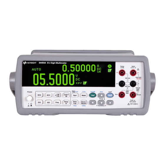
Getting Started Tutorial The Front Panel at a Glance Figure 1-1 34450A front panel Auto range and Manual range Display Resolution, Measurement Speed Power ON/OFF Switch SHIFT (selects blue shifted keys) and Local Key Measurement functions Secondary Display Key Math Operations Input Terminals State Store/Recall, Utility Menu Data Log, View... -
Page 23: The Display At A Glance
Getting Started Tutorial The display at a glance Single display screen Figure 1-2 Typical single display screen Dual display screen Figure 1-3 Typical dual display screen The system annunciators are described in Table 1- (See Table 2- 2 on page 42 for Math Annunciators). 34450A User’s Guide... -
Page 24: Table 1-1 Display Annunciators
Getting Started Tutorial Table 1-1 Display annunciators System Annunciator Description Sample annunciator - indicates readings being taken The keypad has been locked. Press the keys simultaneously for more than 3 seconds to unlock Fixed range is selected for primary function Auto-ranging is selected for primary function Data logging is in progress High input impedance is configured for DCV function... - Page 25 Getting Started Tutorial Table 1-1 Display annunciators (continued) System Annunciator Description Shift key has been pressed Fixed range is selected for secondary function Auto-ranging is selected for secondary function Direct current Alternating current 34450A User’s Guide...
-
Page 26: The Keypad At A Glance
Getting Started Tutorial The Keypad at a Glance The operation for each key is shown in Table 1- 2 below. Pressing a measurement function key changes the current key operation, brings up the relevant symbol on the display (see “The display at a glance” on page 3), and emits a beep. - Page 27 Getting Started Tutorial Table 1-2 Keypad functions (continued) Description • Press to adjust range • Press to adjust values Press to access utility menu. See “Using the Utility Menu” on page 47 > Press simultaneous for 3 seconds to lock and unlock the keypad Measurement functions Press to select DC voltage measurement Press to select AC voltage measurement...
- Page 28 Getting Started Tutorial Table 1-2 Keypad functions (continued) Description Measurement - related functions Press to enable null function. See “Null measurement” on page 33 Press to access math functions menu. See “Math Operations” on page 32 Press to access data logging menu. See “Data Logging”...
-
Page 29: Feature Upgrades
Getting Started Tutorial Feature Upgrades There are two licenses, listed in Table 1- 3, which are available for purchase: Table 1-3 License details Default Factory Settings With Purchase of License Part Number Data Logging Memory 5,000 readings 50,000 readings (Option 3445MEMU) 34450A-801 GPIB Remote Operation Disabled Enabled (Option 3445GPBU) -
Page 30: The Rear Panel At A Glance
Getting Started Tutorial The Rear Panel at a Glance Figure 1-5 Rear panel at a glance Serial Interface Connector USB Interface Connector GPIB with Option 3445GPBU installed Current Fuse Model and Serial Number Label Kensington Lock Chassis Ground Lug AC Power Connector AC Line Fuse AC Line Voltage Selector 34450A User’s Guide... -
Page 31: Making Measurements
For remote operation, refer to the MEASure Subsystem in the Agilent 34450A Online Programmer’s Reference Helpfile. Using the keys The meter functions and operations can be selected by pressing the buttons located on the front panel;... -
Page 32: Digit Masking
Getting Started Tutorial Digit masking The navigation keypad provides a shortcut to mask (change the number of digits displayed) the reading on the main display, easing readability. Masking digits only affects what is displayed. It does not affect measurement speed or accuracy. -
Page 33: Selecting Current Input Terminals And Measurement Range
Getting Started Tutorial Selecting current input terminals and measurement range If AC or DC current is being measured in auto- ranging mode, with a signal input at 100 mA, the meter will select the range 100 µA to 100 mA automatically. If a signal input is applied to the 10 A input terminal, the meter will select the 1 A to 10 A range automatically. -
Page 34: Figure 1-6 Acv Rms And Dcv Terminal Connection And Display
Getting Started Tutorial Typical ACV Measurement Display Typical DCV Measurement Display AC or DC voltage source Figure 1-6 ACV rms and DCV terminal connection and display Do not apply any voltage to the instrument inputs until all terminals WA R N I N G are properly connected. -
Page 35: Measuring Resistance
Getting Started Tutorial Measuring resistance • Measurement Range: 100.000 Ω,, 1.00000 kΩ,, 10.0000 kΩ,, 100.000 kΩ, 1.00000 MΩ, 10.0000 MΩ, 100.000 MΩ. • Speed: Slow, Medium, Fast • Default Setting: Autoranging, Slow measurement speed • Measurement Method: 2-wire ohms or 4-wire ohms •... -
Page 36: Measuring Ac (Rms) Or Dc Current Up To 100 Ma
Getting Started Tutorial Measuring AC (RMS) or DC current up to 100 mA • Measurement Range (AC): 10.0000 mA, 100.000 mA • Measurement Range (DC): 100.000 µA, 1.00000 mA, 10.0000 mA, 100.000 mA • Speed (AC): Slow-2 Hz, Medium-20 Hz, Fast-200 Hz •... -
Page 37: Measuring Ac (Rms) Or Dc Current Up To 10 A
Getting Started Tutorial Measuring AC (RMS) or DC current up to 10 A • Measurement Range (AC): 1.00000 A, 10.0000 A • Measurement Range (DC): 1.00000 A, 10.0000 A • Speed (AC): Slow-2 Hz, Medium-20 Hz, Fast-200 Hz • Speed (DC): Slow, Medium, Fast •... -
Page 38: Measuring Frequency For Voltage
Getting Started Tutorial Measuring frequency for voltage • Measurement Range: 100.000 mV, 1.00000 V, 10.0000 V, 100.000 V, 750.00 V. Range is based on the voltage level of the signal, not frequency. • Speed: Slow, Medium • Measurement Method: Reciprocal counting technique •... -
Page 39: Measuring Frequency For Current
Getting Started Tutorial Measuring frequency for current • Measurement Range: 10.0000 mA, 100.000 mA, 1.00000 A, 10.0000 A. Range is based on the current level of the signal, not frequency. • Speed: Slow, Medium • Measurement Method: Reciprocal counting technique •... -
Page 40: Testing Continuity
Getting Started Tutorial Testing continuity • Measurement Method: 0.5 mA ± 0.2% constant current source • Response Time: 165 samples/second with audible tone • Continuity Threshold: 10 Ω fixed • Input Protection: 1000 V (HI terminal) Open Circuit Measurement Display Open or Closed Circuit Typical Closed Circuit Measurement Display... -
Page 41: Checking Diodes
Getting Started Tutorial Checking diodes • Measurement Method: Uses 0.5 mA ± 0.2% constant current source • Response Time: 190 samples/ second with audible tone • Input Protection: 1000 V (HI terminal) Typical Forward-Biased Diode Measurement Display Forward Bias Press Twice Figure 1-15 Forward-biased diode terminal connection and display Typical Reverse-Biased Diode Measurement Display... -
Page 42: Measuring Temperature
Getting Started Tutorial Measuring temperature • Measurement Range: –80.0 °C to 150.0 °C, –110.0 °F to 300.0 °F • Measurement Method: 2-wire Ohms measurement of 5 kΩ thermistor sensor (E2308A) with computed conversion • Input Protection: 1000 V (HI terminal) •... -
Page 43: Measuring Capacitance
Getting Started Tutorial Measuring capacitance • Measurement Range: 1.000 nF, 10.00 nF, 100.0 nF, 1.000 µF, 10.00 µF, 100.0 µF, 1.000 mF, 10.00 mF • Default Setting: Autoranging • Measurement Method: Computed from constant current source charge time. Typical 0.12 V to 1.0 V AC signal level •... -
Page 44: Selecting A Range
Getting Started Tutorial Selecting a Range You can let the multimeter automatically select the range using autoranging, or you can select a fixed range using manual ranging. Autoranging is convenient because the multimeter automatically selects the appropriate range for sensing and displaying each measurement. However, manual ranging results in better performance, since the multimeter does not have to determine which range to use for each measurement. -
Page 45: Remote Operation
Getting Started Tutorial Remote Operation USB interface Automatically shows the remote state Press to exit Remote state when communication is established after executing the Agilent Connection Expert 34450A User’s Guide... -
Page 46: Serial Interface
N O T E use the Automation- Ready CD, which is shipped with your 34450A. This CD includes the Agilent IO Libraries Suite and the Agilent Connection Expert application. For more information about Agilent's I/O connectivity software, visit www.agilent.com/find/iolib. Serial interface... -
Page 47: Gpib Ieee-488 (Optional)
Getting Started Tutorial The connecting diagram and setup procedure are shown in “Serial interface connector diagram” “RS232 utility sub- menu” on page 52 below. Serial-to-RS232 adapter (34450A-700) Instrument RS232 Protocol Yellow Grey TRIGGER IN TRIGGER OUT Serial Serial Male Female Interface Interface Male... -
Page 48: Code Compatibility Mode
The Agilent 34450A complies with the syntax rules and conventions of SCPI (Standard Commands for Programmable Instruments). For a complete discussion of the 34450A SCPI syntax, refer to the Agilent 34450A N O T E Programmer’s Reference Helpfile, This is provided in the 34450A Product Reference... - Page 49 Getting Started Tutorial • You can query the SCPI version from the remote interface only. • The SCPI version is returned in the form “YYYY.V”, where “YYYY” represents the year of the version, and “V” represents a version number for that year (for example, 1994.0).
- Page 50 Getting Started Tutorial 34450A User’s Guide...
-
Page 51: Functions And Features
Storing and Recalling Instrument States Reset/Power-On State Triggering the Multimeter Data Logging This chapter contains information on the functions and features of the Agilent 34450A 5½ Digit Multimeter and how to use the front panel to operate these settings. Agilent Technologies... -
Page 52: Math Operations
• Range and resolution changing is allowed for all math operations. • The reference/offset/limit values used for the Null, Limit, dB, and dBm math functions are editable. • For remote operation, refer to the CALCulate Subsystem in the Agilent 34450A Programmer’s Reference Helpfile. 34450A User’s Guide... -
Page 53: Null Measurement
Functions and Features Null measurement When making null measurements, also called relative measurement, each reading is the difference between a stored null value and the input signal. For example, this feature can be used to make more accurate resistance measurements by nulling the test lead resistance. -
Page 54: Figure 2-1 Accessing The Null Measurement
Functions and Features Press to enable null measurement shows ongoing measurement, ranging method, range and shows null resolution measurement offset value Typical Null Measurement Display Figure 2-1 Accessing the null measurement After you enable the null operation, the multimeter stores the next reading into the offset register and immediately displays the null measurement: –... -
Page 55: Hold Measurement
Functions and Features Hold measurement The hold feature allows you to capture and hold a stable reading on the front panel display. When a stable reading is detected, the multimeter emits a beep (if the buzzer is enabled in the utility menu) and holds the reading on the primary display. -
Page 56: Limit Measurement
Functions and Features Limit measurement The limit operation allows you to perform pass/fail testing against specified upper and lower limits. > Press to enable limit measurements The upper limit must Shows present always be greater than measurement the lower limit. Otherwise, “INVALID Limit state LIMIT”... -
Page 57: Accessing Math Menu
Functions and Features Accessing math menu The math operation can be enabled using the following steps: Press to display math menu Math menu display 34450A User’s Guide... -
Page 58: Editing Single Statistics
Functions and Features Editing single statistics The single statistics can be edited using the following steps: Press to start Select STATS (SINGLE) option Statistical values Present measurement Typical statistics (single) display for Max reading Press to toggle the Press to edit Max/Min/Avg/N values Maximum reading Minimum reading... -
Page 59: Editing All Statistics
Functions and Features Editing all statistics The all statistics in the math operation can be edited using the following steps: Press to start Select STATS (ALL) Number of readings taken Maximum Present measurement reading Average Minimum reading reading Note: Each time a new min or max value is stored, the multimeter will beep once (if the buzzer is turned on in the utility menu) and the New annunciator is briefly turned on for 1 second in the respective Min or Max box Press to exit... -
Page 60: Editing Db Measurement
Functions and Features Editing dB measurement When enabled, the dB operation computes the dBm value for the next reading, stores the dBm result into the dB Ref register, and immediately produces the following calculation. The first displayed reading is always precisely 000.00 dB. dB = 10 ×... -
Page 61: Editing Dbm Measurement
Functions and Features Editing dBm measurement The logarithmic dBm (decibels relative to one milliwatt) scale is often used in RF signal measurements. The multimeter’s dBm operation takes a measurement and calculates the power delivered to a reference resistance (typically 50, 75, or 600 Ω). The formula used for conversion from the voltage reading is: / 0.001 Ω... -
Page 62: Math Annunciators
(refer to Table 2- 2 on page 42 for a list). For remote operation, refer to the CALCulate Subsystem in the Agilent 34450A Programmer’s Reference Helpfile. 34450A User’s Guide... -
Page 63: Editing Values
Functions and Features Editing values For math functions with editable values, the label “PRESS MATH TO EDIT” will be shown at the bottom left of the display. To edit math values, follow the steps below: Press to display null menu Press for digit selection Press to edit Press to change the value of selected digit... -
Page 64: The Dual Display
Functions and Features The Dual Display Most measurement functions have predefined range or measurement capabilities that can be displayed in the dual measurement mode. All math operations have predefined operations that are displayed on the dual display. Table 2- 3 below shows the measurement functions which are available in dual display mode. -
Page 65: Using The Dual Display
Functions and Features Table 2-4 Measurement operation frequencies for DCV-ACI DCV-ACI Measurement Operation Frequency Slow/Medium >500 Hz (600 Hz) / n x 50 Hz (60 Hz) for <500 Hz Fast >10 kHz / n x 1 kHz for <10 kHz For more information , please refer to Chapter “Measurement Speed Consideration”. - Page 66 Press to turn off secondary display Select desired range Note: For available measurements in the dual display mode, refer to table Table 2-3 Select desired speed For remote operation, refer to the DISPlay:WINDow2 commands in the Agilent 34450A Programmer’s Reference Helpfile. 34450A User’s Guide...
-
Page 67: Using The Utility Menu
Functions and Features Using the Utility Menu The Utility menu allows you to customize a number of non- volatile instrument configurations. It also displays any SCPI error messages and the latest firmware revision codes. The descriptions of the items in the Utility menu and their options are shown in Table 2- 5 on page 48... -
Page 68: Table 2-5 Utility Menu Available Settings
Selects the unit for temperature UNIT:TEMPerature TEMP UNIT °C °C or °F measurements <units> L1 represents Agilent Mode L2 represents Fluke 45/8808A Mode. LANGUAGE L1 or L2 Refer to “Enabling the code SYSTem:LANGuage compatibility function”... - Page 69 Functions and Features Table 2-5 Utility menu available settings (continued) To secure or unsecure the calibration adjustments to the instrument. CALibration:SECure: CALIBRATION SECURE SECURE or UNSEC Selecting it will open the [Calibration STATe <mode>, Sub-Menu] <code> Feature Default Available Settings Description Remote Command Allows you to toggle the brightness on...
- Page 70 Functions and Features Below are the steps you should follow if you want to edit any of the values on the utility menu: > Press to display the utility menu Page one of utility menu Press to edit This option will flash, enabling you to edit Press to exit Press to save Select the desired value...
-
Page 71: Rs232 Utility Sub-Menu
Functions and Features RS232 utility sub-menu To enable the RS232 option, follow the steps below. For a list of RS232 settings, see Table 2- 6 on page 52. Press to edit Select I/O option Press to edit RS232 option Press to select RS232 option Press to edit/save Press to return to utility menu Typical RS232 sub menu display... -
Page 72: Table 2-6 Rs232 Utility Sub-Menu
Functions and Features Table 2-6 RS232 utility sub-menu Option Default Available Settings Description Setting BAUD RATE 9600 300, 600, 1200, 2400, Baud rate for remote 4800, 9600, 19200, communication with a PC 38400, 57600 (remote control) PARITY NONE NONE, ODD, EVEN Parity bit for remote communication with a PC DATA BIT... -
Page 73: Gpib Utility Sub-Menu
GPIB license key is not activated : “GPIB is not enabled, to enable, please visit www.agilent.com/find/34450A” If GPIB connectivity is selected, a sub- menu will appear to allow you configure the address (from 0 to 30) for remote communication to a PC. -
Page 74: Reading Error Messages
Functions and Features Reading error messages To read error messages from the front panel, perform the following procedures. For remote operation, refer to the SYSTem:ERRor? command in the Agilent 34450A Programmer’s Reference Helpfile. > Press to display the utility menu... -
Page 75: The Beeper
Functions and Features The beeper Normally, the multimeter beeps whenever certain conditions are met (for example, the multimeter beeps when a stable reading is captured in reading hold mode). The beeper is factory set to ON, but may be disabled or enabled manually. -
Page 76: Storing And Recalling Instrument States
Functions and Features Storing and Recalling Instrument States The present multimeter state, including all settings for measurement configuration, math operation, and system operations, can be saved in one of the six non- volatile memory location and later recalled. Location LAST retains the multimeter configuration at power down. - Page 77 Press to recall state Memory location selected from the selected Press to select the memory location memory location For remote operation, refer to the MEMory Subsystem, the *SAV, and *RCL commands in the Agilent 34450A Programmer’s Reference Helpfile. 34450A User’s Guide...
-
Page 78: Reset/Power-On State
Functions and Features Reset/Power-On State The table below summarizes the 34450A settings as received from the factory, following power cycling, and following the *RST command received over the USB remote interface. Non- volatile, user customizable behavioral differences are shown in BOLD. Table 2-7 Reset/Power-on state Parameter Factory Setting... - Page 79 Functions and Features Table 2-7 Reset/Power-on state (continued) Parameter Factory Setting Power-On / Reset State Reading Output Buffer Cleared Cleared Error Queue Cleared Cleared if power cycle Power-on Status Clear Enabled User Setting Status Registers, Masks & Transition Cleared Cleared if power-on status clear Filters enabled;...
-
Page 80: Triggering The Multimeter
• Remote Interface Operation: The following command selects the immediate trigger source: TRIGger:SOURce IMMediate The CONFigure and MEASure? commands automatically set the trigger source to IMMediate. Refer to the Agilent 34450A Programmer’s Reference Helpfile for complete description and syntax for these commands. 34450A User’s Guide... - Page 81 • The INITiate command only initiates the measurement and needs a trigger (BUS or EXTernal or IMMEdiate) to make the actual measurement. Refer to the Agilent 34450A Programmer’s Reference Helpfile for the complete description and syntax for these commands. 34450A User’s Guide...
-
Page 82: Figure 2-5 Trigger In Connector
Functions and Features External Trigger External triggering takes one reading (or the specified number of readings in data logger) each time the multimeter receives a pulse on the rear- panel external trigger connector. The multimeter uses the rising edge (POS) of the external trigger signal to trigger a reading. -
Page 83: Figure 2-6 Trigger Out Connector
Functions and Features In data log/external trigger mode, a trigger out signal is sent whenever a measurement is log/triggered and updated on the front panel. In code compatibility mode, a trigger out signal is sent whenever a measurement is updated on the front panel or a measurement is taken by the user using command.The diagram below shows the trigger out connector: TRIG... - Page 84 Functions and Features measurement. Trigger out and manual trigger implement a standard hardware handshake sequence between measurement and switching devices. 34450A User’s Guide...
-
Page 85: Data Logging
Functions and Features Data Logging The data logger feature provides a front- panel interface that allows you to set up data logging into the instrument’s non- volatile memory with programming, and without a connection to a computer. Once you have finished collecting data, you can view it from the front panel, or you can also connect your computer and import the data using the DATA:DATA? NVMEM command. - Page 86 Functions and Features Below are the steps to enable data logging: Press to enable data log menu Typical data log menu display Note: Enabling new log data will Move cursor to enable logging Press to execute automatically delete previous log Press to proceed Typical data log menu screen Press the trigger button (manual triggering) or wait for an external pulse (external triggering)
-
Page 87: Table 2-8 Data Log Menu Options
Functions and Features Table 2-8 Data log menu options Option Available settings Description TRIGGER 0 to 3600 seconds Delay time between a trigger is initiated and first reading is taken by the data log DELAY function. The smallest delay time resolution is 100 µs. SAMPLE 1 to 3600 seconds Delay time between subsequent readings. - Page 88 Functions and Features To edit the trigger delay, sample interval, sample count, and trigger count in the data log menu, follow the steps below: Press to enable data log menu Typical data log menu display Press for digit selection Press to edit Press to change the value of selected digit Press to save Press to exit...
-
Page 89: Viewing The Log Info
Functions and Features Viewing the log info Log info page shows the record number of the log data, function, and range for the primary and secondary measurement when data is logged. If no data is available for that log, NA is displayed. >... -
Page 90: Viewing The Log List
Functions and Features Viewing the log list To view the log list, follow the steps below: > Press to display data log menu Typical log view menu display Typical log list first page display when only the Press to select Move cursor to log list menu primary measurement is performed during data log Typical log list first page display when both primary... -
Page 91: Viewing The Log Histogram
Functions and Features Viewing the log histogram To view the log histogram, follow the steps below: > Press to display data log menu Typical log view menu display Move cursor to the histogram menu Press to select Typical histogram display without secondary measurement function Press to switch between primary or secondary data... -
Page 92: Viewing The Log Statistics
Functions and Features Viewing the log statistics To view the log statistics, follow the steps below: Press to display data log menu Typical log view menu display Press to select Move cursor to the log statistics menu Press to exit Typical log statistics display 34450A User’s Guide... -
Page 93: Fluke 45/Fluke 8808A Code Compatibility Mode
Functions and Features Fluke 45/Fluke 8808A Code Compatibility Mode The code compatibility mode enables the user to enter remote commands easily when migrating from one instrument to the next. Enabling the code compatibility function > Press to display utility menu Typical log utility menu display Note: RS232 or GPIB connectivity must be enabled in order for the code compatibility mode to work. -
Page 94: Notes For Fluke 45/Fluke 8808A Code Compatibility Mode
Functions and Features Notes for Fluke 45/Fluke 8808A code compatibility mode • When the code compatibility function is enabled, the front panel will be in a locked state except the utility menu. • Reset is performed on the multimeter whenever the code compatibility function is turned on or turned off. -
Page 95: Measurement Tutorial
True RMS AC Measurements Other Primary Measurement Functions Other Sources of Measurement Error The Agilent 34450A multimeter is capable of making very accurate measurements. In order to achieve the greatest degree of accuracy, you must take the necessary steps to eliminate potential measurement errors. -
Page 96: Dc Measurement Considerations
Measurement Tutorial DC Measurement Considerations Thermal EMF Errors Thermoelectric voltages are the most common source of error in low–level DC voltage measurements. Thermoelectric voltages are generated when you make circuit connections using dissimilar metals at different temperatures. Each metal- to- metal junction forms a thermocouple, which generates a voltage proportional to the junction temperature. -
Page 97: Noise Rejection
Measurement Tutorial Noise Rejection Rejecting Power Line Noise Voltages A desirable characteristic of integrating analog- to- digital (A/D) converters is their ability to reject power- line related noise present with DC input signals. This is called normal mode noise rejection, or NMR. The multimeter achieves NMR by measuring the average DC input by “integrating”... - Page 98 Measurement Tutorial Noise Caused by Magnetic Loops If you are making measurements near magnetic fields, take caution to avoid inducing voltages in the measurement connections. You should be especially careful when working near conductors carrying large currents. Use twisted- pair connections to the multimeter to reduce the noise pickup loop area, or dress the test leads as close together as possible.
-
Page 99: Figure 3-2 Noise Caused By Ground Loops
Measurement Tutorial Ideal test Meter > 10 G Ω ground = Lead Resistance = Multimeter Isolation Resistance = Voltage Drop on Ground Bus ground Figure 3-2 Noise caused by ground loops The best way to eliminate ground loops is to isolate the multimeter from earth by not grounding the input terminals. -
Page 100: Measurement Speed Consideration
Measurement Tutorial Measurement Speed Consideration There are two methods of integrating the sampled data taken in the measurement, slow/medium (NPLC) and fast (Aperture). When you set the resolution to slow or medium, you can not only achieve improved accuracy associated with time averaging, but also achieve the rejection of the power- line interference (normal mode rejection, or NMR). -
Page 101: Dual Measurement Considerations
Measurement Tutorial Dual Measurement Considerations The dual measurements mode allows users to make two measurements in one display. During dual measurement mode, the display will show two separate measurements and there is a switching delay between both measurements. The table below shows some of the applications that can be measured using dual measurement mode: Dual Functions Combinations Application... -
Page 102: Voltage And Current In Dual Measurement
Measurement Tutorial 1.2 V -1.2 V Figure 3-3 ADC Dynamic Range Consider an AC component of 1 Vrms signal with a DC offset of 100 mV. When measuring at DCV 1 V range, Vpeak of the signal is 1.514 V which exceeds the ADC dynamic range of 1.2 V, causing an error in DC measurement. -
Page 103: Figure 3-4 Example Of Measuring Voltage And Current In Dual
Measurement Tutorial Considering the internal resistance and external lead resistance total is 0.0125 ohm. If applying a 1 A DC current, an error of (0.0125 ohm x 1 A) 0.0125 V or 12.5 mV will occur. This error will be relative by range with the ADC dynamic range of 1.2 V. -
Page 104: Resistance Measurement Considerations
Measurement Tutorial Resistance Measurement Considerations When measuring resistance, the test current flows from the input HI terminal through the resistor being measured. The voltage drop across the resistor being measured is sensed internal to the multimeter. Therefore, test lead resistance is also measured. - Page 105 Measurement Tutorial Table 3-2 Examples of measurement ranges (continued) Range Test Current DUT Power at Full Scale 10 MΩ 100 nA 100 nW 100 MΩ 100 nA / 10 MΩ µ Errors in High Resistance Measurements When you are measuring large resistances, significant errors can occur due to resistance insulation and surface cleanliness.
- Page 106 Measurement Tutorial Thermal EMF caused by dissimilar metals can create a parasitic voltage in the measurement circuit (VEMF). The thermal EMF can be caused by the input lead connections or internally in resistor R. In general, this voltage will not change with the current applied to the resistor.
-
Page 107: True Rms Ac Measurements
AC + DC RMS The multimeter’s AC voltage and AC current functions measure the AC- coupled true RMS value. In this Agilent instrument, the “heating value” of only the AC components of the input waveform are measured (DC is rejected). As seen in the figure above;... - Page 108 Measurement Tutorial is a DC voltage content, which is rejected by Agilent’s AC- coupled true rms measurements. This can provide a significant benefit. An AC- coupled true rms measurement is desirable when you are measuring small AC signals in the presence of large DC offsets.
-
Page 109: Table 3-3 Typical Errors For Various Pulse Waveforms As A Function Of Input Pulse Frequency
Measurement Tutorial Notice that crest factor is a composite parameter, dependent upon the pulse- width and repetition frequency; crest factor alone is not enough to characterize the frequency content of a signal. Traditionally, digital multimeters include a crest factor derating table that applies at all frequencies. The measurement algorithm used in the 34450A multimeter is not inherently sensitive to crest factor, so no such derating is necessary. - Page 110 Measurement Tutorial Table 3-3 Typical errors for various pulse waveforms as a function of input pulse frequency (continued) Typical error for square wave, triangular wave, and pulse trains of CF=3, 5, or 10 Square wave Triangle wave CF=3 CF=5 CF=10 50000 –...
-
Page 111: Other Primary Measurement Functions
Measurement Tutorial Other Primary Measurement Functions Frequency measurement errors The multimeter uses a reciprocal counting technique to measure frequency. This method generates constant measurement resolution for any input frequency. All frequency counters are susceptible to errors when measuring low- voltage, low- frequency signals. The effects of both internal noise and external noise pickup are critical when measuring “slow”... -
Page 112: Dc Current Measurements
Measurement Tutorial DC current measurements When you connect the multimeter in series with a test circuit to measure current, a measurement error is introduced. The error is caused by the multimeter’s series burden voltage. A voltage is developed across the wiring resistance and current shunt resistance of the multimeter, as shown below. -
Page 113: Capacitance Measurements
Measurement Tutorial Capacitance measurements The multimeter implements capacitance measurements by applying a known current to the capacitor as shown below: offset offset charged Measurement Model Measurement Model (during charge phase) (during discharge phase) Figure 3-6 Applying current to the capacitor Capacitance is calculated by measuring the change in voltage (ΔV) that occurs over a “short aperture”... - Page 114 Measurement Tutorial Range Current Source Reading Rate at Full Scale 1 mF 0.25/second µ 10 mF 1 mA 0.15/second The values of capacitance and loss resistance measured with the multimeter may differ from the values measured using an LCR meter. This is to be expected, since this is essentially a DC measurement method, while LCR measurement uses applied frequencies anywhere from 100 Hz to 100 kHz.
-
Page 115: Temperature Measurements
– commonly to 80 °C to 150 °C. Thermistors have highly non- linear, temperature- resistance relationships; therefore their conversion algorithms are more complex. Agilent multimeters use the standard Hart- Steinhart Approximation to provide accurate conversions. 34450A Users Guide... -
Page 116: Other Sources Of Measurement Error
Measurement Tutorial Other Sources of Measurement Error Loading Errors (AC volts) In the AC voltage function, the input of the multimeter appears as a 1 MW resistance in parallel with 100 pF of capacitance. The cabling that you use to connect signals to the multimeter also adds capacitance and loading. - Page 117 Measurement Tutorial Temperature changes inside the multimeter due to self- heating may cause additional error on other AC voltage ranges. AC Current Measurement Errors (Burden Voltage) Burden voltage errors, which apply to DC current, also apply to AC current measurements. However, the burden voltage for AC current is larger due to the multimeter’s series inductance and your measurement connections.
- Page 118 Measurement Tutorial Most extraneous noise is not correlated with the input signal. You can determine the error as shown below. Voltage Measured = + Noise Correlated noise, while rare, is especially detrimental. Correlated noise always adds directly to the input signal. Measuring a low- level signal with the same frequency as the local power line is a common situation that is prone to this error.
-
Page 119: Specifications
Agilent 34450A 5 ½ Digit Multimeter User’s Guide Specifications Test Considerations DC Specifications AC Specifications Temperature and Capacitance Specifications Operating Specifications General Characteristics This chapter describes the multimeter’s specifications and operating specifications Agilent Technologies... -
Page 120: Test Considerations
• Electrostatic discharges of 4000 V or greater may cause the multimeter to temporarily stop responding, resulting in a lost or erroneous reading. Specifications are subject to change without notice. For the latest specifications, go to the N O T E product page at www.agilent.com/find/34450A 34450A User’s Guide... -
Page 121: Dc Specifications
Specifications DC Specifications Specifications are for 90 minutes warm- up time, slow mode, and operating temperature within 18 °C – 28 °C Table 4-1 DC accuracy ± (% of reading + % of range) Temperature Test Current or 1 Year Coefficient Function Range... - Page 122 Specifications Table 4-1 DC accuracy ± (% of reading + % of range) (continued) Temperature Test Current or 1 Year Coefficient Function Range Input Impedance 0 °C – 18 °C Burden Voltage 23 °C ± 5° C 28 °C – 55 °C 1000 Ω...
-
Page 123: Ac Specifications
Specifications AC Specifications Specifications are for 90 minutes warm- up time, slow mode, and operating temperature within 18 °C – 28 °C Table 4-2 AC accuracy ± (% of reading + % of range) Temperature Coefficient 1 Year 0 °C – 18 °C Function Range Frequency... -
Page 124: Table 4-3 Frequency Accuracy ± (% Of Reading + Count)
Specifications Table 4-3 Frequency accuracy ± (% of reading + count) Temperature Coefficient 1 Year Function Range Frequency 0 °C to 18 °C 23 °C ± 5 °C 28 °C to 55 °C 20 Hz – 300 kHz 100.000 mV to 750.00 V 0.02 + 3 0.005 Frequency... -
Page 125: Temperature And Capacitance Specifications
Specifications Temperature and Capacitance Specifications Specifications are for 90 minutes warm- up time, slow mode and operating temperature within 18 °C – 28 °C Table 4-5 Temperature and capacitance accuracy ± (% of reading + % of range) Temperature Coefficient Probe Type 1 Year Function... -
Page 126: Operating Specifications
Specifications Operating Specifications Table 4-6 Operating specifications on single display (approximate) Function Range Auto Reading Rate /sec Function Resolution Change Change Range GPIB Serial (sec) (sec) (sec) Slow (5.5) Med (4.5) Fast (4.5) Slow (5.5) Med (4.5) Fast (4.5) Slow (5.5) 2-Wire Ω... - Page 127 Specifications Table 4-6 Operating specifications on single display (approximate) (continued) Function Range Auto Reading Rate /sec Function Resolution Change Change Range GPIB Serial (sec) (sec) (sec) Diode Continuity Temperature [1] Time to change from 2-wire resistance to this specified function and to take at least one reading using SCPI “FUNC” and “READ?”...
-
Page 128: Supplemental Measurement Specifications
Specifications Supplemental measurement specifications Table 4-7 Supplemental measurement specifications DC Voltage • Measuring Method: • Sigma Delta A-to-D converter • Input Resistance: • >10 GΩ ± 2% range (Selectable 100 mV, 1 V ranges) • 10 MΩ ± 2% range (typical) •... - Page 129 Specifications Table 4-7 Supplemental measurement specifications (continued) Continuity / Diode Test • Measurement Method: • Uses 0.5 mA ± 0.2% constant current source • Response Time: • Continuity : 165 samples/second with audible tone • Diode : 190 samples/second with audible tone •...
- Page 130 Specifications Table 4-7 Supplemental measurement specifications (continued) AC Voltage • Measurement Method: • AC coupled true-RMS - measures the AC component with up to 400 VDC bias any range • Crest Factor: • Maximum 3:1 at full scale • Input Impedance: •...
- Page 131 Specifications Table 4-7 Supplemental measurement specifications (continued) • Input Protection: • 750 V rms on all ranges (HI terminal) Math Functions • Null, dBm, dB, Min/Max/Avg, Hold, Limit Test Data Log • Info, List, Histrogram Triggering and Memory • Samples per Trigger: 1 to 5,000 (typical) ,1 to 50,000 (optional) •...
-
Page 132: General Characteristics
Specifications General Characteristics Table 4-8 General characteristics Power Supply • 100 V/120 V(127 V)/220 V(230 V)/240 V ± 10% AC line frequency 45 Hz – 66 Hz and (360 Hz – 440 Hz, 100/120 V operation) • • Automatically sensed at power-on Power Consumption •... - Page 133 Specifications Table 4-8 General characteristics Shock and Vibration • Tested to IEC/EN 60086-2 Dimension (H×W×D) • Rack: 88.5 mm × 212.6 mm × 272.3 mm • Bench: 103.8 mm × 261.1 mm × 303.2 mm Weight • 3.75 kg (8.27 lb.) Warm-Up Time •...
-
Page 134: To Calculate Total Measurement Error
Specifications To calculate total measurement error The multimeter’s accuracy specifications are expressed in the form: ( % of reading + % of range ). In addition to the reading error and range error, you may need to add additional errors for certain operating conditions. Check the list below to make sure you include all measurement errors for a given function. -
Page 135: Accuracy Specifications
Specifications Accuracy specifications Transfer Accuracy Transfer accuracy refers to the error introduced by the multimeter due to noise and short term drift. This error becomes apparent when comparing two nearly equal signals for the purpose of “transferring” the known accuracy of one device to the other. -
Page 136: Configuring For Highest Accuracy Measurements
Specifications Configuring for highest accuracy measurements The measurement configurations shown below assume that the multimeter is in its power on or reset state. It is also assumed that auto- ranging is enabled to ensure proper full scale range selection. • Select slow mode for 5½ digits. •... - Page 137 (tel) 0800 047 866 (fax) 0800 286 331 Other Asia Pacific Countries: (tel) (65) 6375 8100 (fax) (65) 6755 0042 Or visit Agilent World Wide Web at: www.agilent.com/find/assist Product specifications and descriptions in this document are subject to change with- out notice.
Need help?
Do you have a question about the 34450A 5½ Digit Multimeter and is the answer not in the manual?
Questions and answers