Table of Contents
Advertisement
Quick Links
Order parts online
www.follettice.com
Following installation, please forward this manual
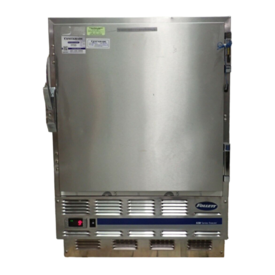
-30 C Undercounter Plasma Freezer
Installation, Operation and Service Manual
to the appropriate operations person.
801 Church Lane • Easton, PA 18040, USA
Toll free (800) 523-9361 • (610) 252-7301
Fax (610) 250-0696 • www.follettice.com
Serial numbers C45184 and above
00193482R00
Advertisement
Table of Contents

Related Manuals for Follett C45184


Summary of Contents for Follett C45184
- Page 1 Following installation, please forward this manual to the appropriate operations person. 801 Church Lane • Easton, PA 18040, USA Toll free (800) 523-9361 • (610) 252-7301 Fax (610) 250-0696 • www.follettice.com Installation, Operation and Service Manual Serial numbers C45184 and above 00193482R00...
-
Page 3: Welcome To Follett
After uncrating and removing all packing material, inspect the equipment for concealed shipping damage. If damage is found, notify the shipper immediately and contact Follett Corporation so that we can help in the fi ling of a claim, if necessary. -
Page 4: Installation
Turn legs clockwise to extend legs. Temperature surveillance module Follett’s all-in-one temperature alarm and chart recorder module (manufactured for Follett by Dickson) may be included with your FZR5-PL. Please refer to the Dickson instructions packed with this module for set-up and operation instructions. - Page 5 Reversing the door swing – optional NOTICE When reinstalling latch and hinge screws, 242 blue Loctite* MUST be applied to screws. Torque screws to 25 in-lbs. 1. Remove screws and latch from refrigerator cabinet (Fig. 2.1). 2. Use fl at screwdriver to carefully remove (do not scratch) hinge covers (Fig.
- Page 6 C (-31 F) and turn on when the cabinet reaches -33 C (-27 F). This temperature may not refl ect the temperature of the blood products in the freezer. The temperature of the blood products will be refl ected on the recorder chart and the recorder's digital temperature display. At times there may be a difference between the two displayed temperatures.
-
Page 7: Controller Security
1. Press UP and DOWN ARROW buttons together for 3 seconds until “Pon” displays (will fl ash 3 times). 2. Programmer is now unlocked. Controller programming key degrees C (optional accessory) A controller programming key is available from Follett to provide fast and easy reprogramming of factory settings (part# 00193391). -
Page 8: Operation
Contact 2 is closed and the defrost heater is energized. The melting snowfl ake LED on the controller will come on, and the temperature display will read: “dEF” to indicate the freezer is in the defrost cycle. -
Page 9: Annual Cleaning
5. Adjust latch and or striker as necessary for proper door closure. Slide-out compressor tray Follett’s slide-out compressor tray allows technicians to partially slide the condensing unit from the freezer back without cutting refrigerant lines. 1. Remove rear panel (Fig. 8.1). -
Page 10: Controller Replacement
Disconnect power cord. 2. Remove 6 screws from front panel and slide panel forward to access back of controller. 3. Disconnect front panel and wiring harness from freezer at the 3, 4, and 5 pin connectors and door heater to simplify replacement. -
Page 11: Checking Refrigeration System Pressures
This change can adversely affect the performance of your freezer. Therefore, Follett recommends that if hoses are ever connected to the refrigeration system for service, the refrigerant should be recovered, the system evacuated, and recharged by weighing in the correct refrigerant charge. -
Page 12: Before Calling For Service
Freezer does not shut off. Freezer does not maintain temperature (all components run). Evaporator does not defrost. If problems persist after following this basic troubleshooting guide, call Follett’s technical service group at (800) 523-9361 or (610) 252-7301. Freezer troubleshooting guide Possible cause 1. -
Page 13: Replacement Parts
Replacement parts Evaporator Reference # Description Cover, evaporator (includes 00152892) Fan guard Fan blade Bracket, fan motor Fan motor, evaporator Defrost heater Drain pan, evaporator, FZR5 Evaporator Heater safety switch Expansion valve (includes 00106534) Insulation, bulb Air baffle Clips, defrost heater (2 needed) Part # 00155564 00152892... - Page 14 Condensing Unit Reference # Description Condensing unit Condenser Shroud, condenser Condenser fan blade Condenser fan motor Fan motor bracket Compressor Starting capacitor Filter drier Not shown Cap, starting capacitor Not shown Starting relay Not shown Overload protector Part # 00153874 00157339 00157347 00105007...
- Page 15 Hardware Reference # Description Latch & striker includes screws Latch screws, 3 per latch Door (includes gasket - 21 3/8" x 21 3/8") Hinge, each - 2 required, includes screws Hinge screws, each - 6 per hinge Gasket Strip sealer (set of 4) Drawer (includes 8 and 4 each of 10, 11 &...
- Page 16 Hardware & electrical components Reference # Description Temperature controller Not shown Temperature probe & harness Power switch Front panel (includes 00114371 and 00105379) Front panel screws, each - 6 per panel Not shown Rear panel, includes screws Not shown Rear panel screws, each - 6 per panel Condensate pan Evaporator drain line, sold by the foot Not shown...
Need help?
Do you have a question about the C45184 and is the answer not in the manual?
Questions and answers