Table of Contents
Advertisement
Quick Links
Order parts online
www.follettice.com
Installation, Operation and Service Manual
Following installation, please forward this manual
to the appropriate operations person.
801 Church Lane • Easton, PA 18040, USA
Toll free (800) 523-9361 • (610) 252-7301
Fax (610) 250-0696 • www.follettice.com
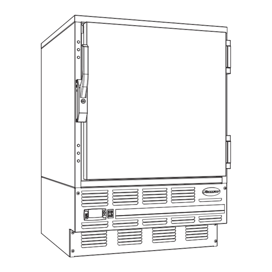
Undercounter Freezer
Serial numbers C45184 to C83253
1
FZR Series
00193474R03
Advertisement
Table of Contents

Related Manuals for Follett C83253


Summary of Contents for Follett C83253
- Page 1 Undercounter Freezer Order parts online Installation, Operation and Service Manual www.follettice.com Serial numbers C45184 to C83253 Following installation, please forward this manual to the appropriate operations person. 801 Church Lane • Easton, PA 18040, USA Toll free (800) 523-9361 • (610) 252-7301 Fax (610) 250-0696 •...
-
Page 2: Welcome To Follett
After uncrating and removing all packing material, inspect the equipment for concealed shipping damage. If damage is found, notify the shipper immediately and contact Follett Corporation so that we can help in the fi ling of a claim, if necessary. -
Page 3: Installation
C display. The -25 C (-13 F) set point delivers a temperature range of -23 to -25 C (-9 to -13 F). Follett’s controller set point can be changed to deliver up to a -15 C (+5 F) temperature for applications where a lower temperature is not desired (i.e. - Page 4 Reversing the door swing – optional Fig. 4 NOTICE When reinstalling latch and hinge screws, 242 blue Loctite* MUST be applied to screws. Torque screws to 25 in-lbs. 1. Remove screws and latch from refrigerator cabinet (Fig. 4.1). 2. Use fl at screwdriver to carefully remove (do not scratch) hinge covers (Fig.
- Page 5 Controller operation Fig. 7 In normal operation the controller displays cabinet temperatures refrigeration evaporator system in degrees C (default) or user-selected degrees F. Degrees C energized energized temperatures are displayed to 1 decimal point. Rocker buttons to the right of the temperature display control all °C programming functions.
-
Page 6: Controller Security
1. Press UP and DOWN ARROW buttons together for 3 seconds until “Pon” displays (will fl ash 3 times). 2. Programmer is now unlocked. Controller programming key A controller programming key is available from Follett to provide fast and easy reprogramming of factory settings. Program Key reference Chart FZR4ADA &... -
Page 7: Operation
+5 C (+41 F) or after 15 minutes, whichever came fi rst. If you are experiencing problems with frost on any of these earlier units, please call Follett's technical service department at (800) 523-9361 or (610) 252-7301 for a programming key to update your unit to the most current program settings. -
Page 8: Latch Adjustment
Annual cleaning Fig. 8 Removal of dust and other particulates from air intake areas and the condenser is important for proper operation. Some environments with large amounts of dust may require more frequent cleaning. 1. Disconnect power to unit by turning switch on the lower front panel to the OFF position, switching circuit breaker to OFF position, and removing power cord from receptacle. -
Page 9: Slide-Out Compressor Tray
Slide-out compressor tray Follett’s slide-out compressor tray allows technicians to partially slide the condensing unit from the freezer back without cutting refrigerant lines. 1. Remove rear panel (Fig. 10.1). 2. Remove two bolts securing condensing unit to refrigerator base (Fig. 10.2). -
Page 10: Checking Refrigeration System Pressures
This change can adversely affect the performance of your freezer. Therefore, Follett recommends that if hoses are ever connected to the refrigeration system for service, the refrigerant should be recovered, the system evacuated, and recharged by weighing in the correct refrigerant charge. -
Page 11: Before Calling For Service
3. Replace controller. controller (during defrost). 4. Defrost settings may require 4. Call Follett's technical service change for specifi c applications. department. If problems persist after following this basic troubleshooting guide, call Follett’s technical service group at (800) 523-9361 or (610) 252-7301. -
Page 12: Accessory Installation
Accessory Installation Temperature Alarm Accessory for REF and FZR Series Materials supplied Fig. 11 (1) Alarm module (1) 4" stainless probe with 8 ft cable (1) Short length of Tygon tubing (for FZR applications only) (1) Power supply with 5 ft cord (1) Probe bottle with internal gasket and screw-on cap (2) Bottle bracket (long and short) (1) 9-volt battery... - Page 13 REF4-ADA and REF5 refrigerators only Fig. 14 Route probe through grommeted hole in back of refrigerator where refrigeration lines enter the cabinet. Power All models Push probe down through gasketed bottle top and insert into bottle bracket. Black Note: Alarm probe must be placed in bottle for proper White Sensor system operation.
-
Page 14: Automated Medication Dispensing And Inventory Systems Interface
Viewing high/low log Follett’s alarm module allows users to view the highest and lowest temperatures recorded since the last time the RESET button was pressed. To view high and low log values 1. Press SET button until “HI” appears. 2. Press SET button to view HI log value. -
Page 15: Temperature Surveillance Module Accessory
Temperature Surveillance Module Accessory Materials supplied Fig. 16 (1) Temperature surveillance module (1) 4" stainless probe with 8 ft cable Switch Switch Feature Selection DOWN (1) Short length of Tygon tubing (for FZR applications only) Recording 7 days (1) Power supply with 5 ft cord time 24 hr (1) Probe bottle with internal gasket and screw-on cap... - Page 16 Place the chart recorder on a fl at vibration-free surface or mount it on wall using keyhole slots on back. Replacement charts (item #00162099) and replacement pens (item #00162081) can be ordered from Follett by calling Technical Service at 800-523-9361.
-
Page 17: Replacement Parts
Replacement parts Evaporator Reference # Description Part # Cover, evaporator, FZR5 (includes 00152892) 00155564 Cover, evaporator, FZR4-ADA (includes 00152892) 00155572 Fan guard 00152892 Fan blade 00152991 Bracket, fan motor 00152983 Fan motor, evaporator 00104919 Defrost heater 00152645 Drain pan, evaporator, FZR5 00162511 Drain pan, evaporator, FZR4-ADA 00155614... - Page 18 Condensing Unit Reference # Description Part # Condensing unit 00153874 Condenser 00157339 Shroud, condenser 00157347 Condenser fan blade 00105007 Condenser fan motor 00104992 Fan motor bracket 00157412 Compressor 00157313 Starting capacitor 00104968 Filter drier 502724 Not shown Starting relay 00157305 Not shown Overload protector 00104984...
- Page 19 Hardware Reference # Description Part # Latch & striker includes screws 00105023 Latch screws, 3 per latch 00103507 Door, FZR5 (includes gasket - 21 3/8" x 21 3/8") 00105015 Door, FZR4-ADA (includes gasket - 21 3/8" x 18 5/8") 00113910 Hinge, each - 2 required, includes screws 00105031 Hinge screws, each - 6 per hinge...
- Page 20 Hardware & electrical components Reference # Description Part # Temperature controller 00900092 Not shown Temperature probes & harness 00155705 Power switch 00114371 Front panel (includes 00114371 and 00105379) 00157669 Front panel screws, each - 6 per panel 00105379 Not shown Rear panel, includes screws 00130161 Not shown...
Need help?
Do you have a question about the C83253 and is the answer not in the manual?
Questions and answers