
Related Manuals for ADTRAN 1200312L5


Summary of Contents for ADTRAN 1200312L5
- Page 1 VCOM Module User Manual Part Numbers 1200312L5 4 Channels 1200312L1 8 Channels 1200312L2 16 Channels 1200312L3 24 Channels 61200312L1-1C April 2000...
- Page 2 901 Explorer Boulevard P.O. Box 140000 Huntsville, AL 35814-4000 (256) 963-8000 © 2000 ADTRAN, Inc. All Rights Reserved. Printed in U.S.A.
- Page 3 Warranty and Customer Service ADTRAN will replace or repair this product within five years from the date of shipment if the product does not meet its published specification, or if it fails while in service. For detailed warranty, repair, and return information, refer to the ADTRAN Equipment Warranty and Repair and Return Policy.
- Page 4 Customer or a third party (including, but not limited to, loss of data or information, loss of profits, or loss of use). ADTRAN is not liable for dam- ages for any cause whatsoever (whether based in contract, tort, or otherwise) in excess of the amount paid for the item.
-
Page 5: Table Of Contents
Physical Description ............................1-2 Related Documentation ........................... 1-2 Chapter 2 Installation ..........................2-1 Unpack and Inspect ............................2-1 Contents of Adtran Shipment ........................2-1 Installing the VCOM Module ......................... 2-1 Power-up and Initialization ..........................2-3 Failed Self-test ..............................2-3 Chapter 3 Operation ............................ 3-1 Overview ................................ - Page 6 Table of Contents Device ................................. 3-5 State ................................3-5 N/A ..............................3-5 Available .............................. 3-6 Busy ..............................3-6 Testing ..............................3-6 Failed ..............................3-6 Algorithm ..............................3-6 N/A ..............................3-6 G.723.1 ..............................3-6 Netcoder .............................. 3-6 Silence ................................. 3-6 Connection ..............................3-6 Frame Type ..............................
-
Page 7: List Of Figures
List of Figures Figure 2-1. VCOM Rear Chassis........................2-2 Figure 3-1. VCOM Module Menu Tree ......................3-2 Figure 3-2. Modules Menu with VCOM Installed..................3-2 Figure 3-3. VCOM Menus ..........................3-5 61200312L1-1 VCOM Module User Manual... - Page 8 List of Figures viii VCOM Module User Manual 61200312L1-1...
-
Page 9: Chapter 1 Introduction
The VCOM Module ordering options provide 4, 8, 16, 24, or 30 voice compression resources. • The VCOM Module provides automatic selection of CCITT Standard or ADTRAN-proprietary voice compression algorithms based on endpoint configuration. • The VCOM Module supports FAX at 14400 bps. -
Page 10: Physical Description
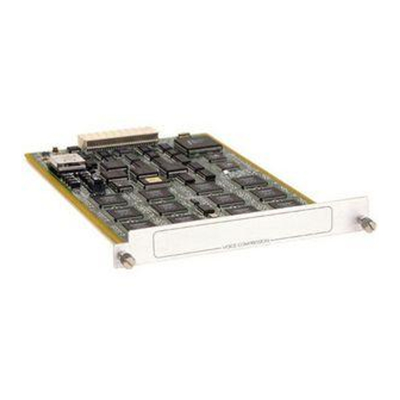
Chapter 1. Introduction PHYSICAL DESCRIPTION The VCOM Module provides no external interfaces. Other ATLAS 550 components provide both the network and customer interfaces. An internal bus exchanges information between the ATLAS 550 chassis and the VCOM Module. RELATED DOCUMENTATION The following document contains additional information about the ATLAS 550 frame relay feature: •... -
Page 11: Chapter 2 Installation
Carefully inspect the VCOM Module for shipping damages. If you suspect damage, file a claim immediately with the carrier and then contact ADTRAN Technical Support. If possible, keep the original shipping container for returning the VCOM Module for repair or for verification of shipping damage. -
Page 12: Figure 2-1. Vcom Rear Chassis
Chapter 2. Installation Instructions for Installing the VCOM Module Step Action On the rear of the ATLAS 550 chassis, remove the cover plate covering the slot into which the option module carrying the VCOM resource module is to be inserted. If theATLAS 550 option module is already in the ATLAS 550 chassis, simply loosen the thumbscrews at both edges of the option module faceplate and slide the module out of the chassis. -
Page 13: Power-Up And Initialization
Chapter 2. Installation POWER-UP AND INITIALIZATION After installing the VCOM Module into the ATLAS 550 chassis, the front panel S indicator blinks red, yellow, and green for a time. The S TATUS TATUS indicator remains solid green when the VCOM Module is ready to use. At this time, you can invoke a system self-test;... - Page 14 Chapter 2. Installation VCOM Module User Manual 61200312L1-1...
-
Page 15: Chapter 3 Operation
Operation Chapter 3 OVERVIEW You can configure, control, diagnose, and view the status of the VCOM Module with the terminal menus. This chapter describes the menu items available for operating the VCOM Module using the terminal menu. Security Passwords You must have the appropriate password level to use the terminal menu to edit items. -
Page 16: Figure 3-1. Vcom Module Menu Tree
Chapter 3. Operation Part Number Info Serial Number Assembly Revision Firmware Revision Type Menu Device Modules Alarm Status State Test Algorithm State Silence Status Connection Frame Type Config Device State Device Test Usage Time ATLAS Frms ATLAS Drop VCOM Frms VCOM Drop Clear Reloads... -
Page 17: Menu Access
Chapter 3. Operation MENU ACCESS The ATLAS 550 system controller automatically detects the presence of the VCOM Module as it is installed into the system. To access the VCOM menus and submenus, use the keyboard arrow keys to scroll to the ODULE appropriate row and column;... -
Page 18: State
Chapter 3. Operation Read Security: 5 TATE Denotes the module as O or O . Even though a module is physi- NLINE FFLINE cally installed, it must be marked O for it to be considered an available NLINE resource. Marking an installed module O may be useful during system trouble- FFLINE shooting. -
Page 19: Vcom Menus
Figure 3-3. VCOM Menus Read Security: 5 Displays module and software information for the VCOM module. Read Security: 5 UMBER Displays the ADTRAN part number for the module (read-only). Read Security: 5 ERIAL UMBER Displays the VCOM Module's serial number. -
Page 20: Available
Not available. This device has not been assigned a voice compression algo- rithm. G.723.1 CCITT G.723.1 compression; 6.3 kbps bandwidth. ADTRAN-proprietary NETCODER compression; 6.4 kbps bandwidth. ETCODER Some voice compression standards are proprietary and may be used only under specific licensing arrangements. The ATLAS 550 provides complete management of these licensed resources;... -
Page 21: Frame Type
Chapter 3. Operation Read Security: 5 RAME Displays the kind of frame the ATLAS 550 receives from the frame relay endpoint connected to the VCOM channel, allowing users to monitor the kind of data being carried on the network and processed by the ATLAS 550. (The ATLAS 550 interprets the most-recently received frame from the end- point.) During a voice connection, the frame type displays as V... -
Page 22: Config
VCOM Module. If a malfunction is suspected on the VCOM module, ADTRAN service personnel can use this menu to locate the prob- lem. This menu is documented here in the interest of completeness. The values automatically reset each time the VCOM Module is installed into the the ATLAS 550 chassis. -
Page 23: Usage Time
Chapter 3. Operation Read Security: 5 SAGE Measures the total elapsed time that a VoFR device has the status BUSY. The time is expressed with millisecond precision. Available VoFR devices are assigned new connections using a round-robin technique where all other available VoFR devices must be used before a given device is assigned a new connection. -
Page 24: Vcom Drop
Chapter 3. Operation VCOM D Read Security: 5 Counter-measures each frame dropped or discarded by VCOM Module during communication with the ATLAS 550 system controller about a VoFR device. The exchange protocol is designed so that no frames should be dis- carded during this operation. -
Page 25: Atlas Features Used With Vcom Modules
Chapter 3. Operation ATLAS FEATURES USED WITH VCOM MODULES In addition to the VCOM menu items, the ATLAS 550 system provides additional services that operate in conjunction with the VCOM Module: and S ACTORY ESTORE YSTEM ACTORY The factory default settings for the VCOM Module can be restored from the terminal menus. - Page 26 Chapter 3. Operation 3-12 VCOM Module User Manual 61200312L1-1...
-
Page 27: Index
Index RMA iii accessing menus 3-3 ATLAS 550 menus and submenus Factory Restore 3-11 self-test Modules 3-3 failed 2-3 Alarm 3-3 service iii Menu 3-3 shipping Rev 3-4 contents 2-1 Slt 3-3 damage 2-1 State 3-4 Status 3-4 Empty 3-4 No Response 3-4 VCOM menus and submenus 3-5 Not Ready 3-4... - Page 28 Index State (Busy) 3-6 Reloads 3-10 State (Failed) 3-6 Usage Time 3-9 State (N/A) 3-5 VCOM Drop 3-10 State (Testing) 3-6 VCOM Frms 3-9 StatusFrame Type, Blank 3-7 VoFR capability 1-1 Test 3-8 ATLAS Drop 3-9 ATLAS Frms 3-9 warranty iii Clear 3-10 Device 3-8 Index-2...
- Page 29 (888) 4ADTRAN Repair and Return If ADTRAN Technical Support determines that a repair is needed, Technical Support will coordinate with the Customer and Product Service (CAPS) department to issue an RMA number. For informa- tion regarding equipment currently in house or possible fees associated with repair, contact CAPS...
Need help?
Do you have a question about the 1200312L5 and is the answer not in the manual?
Questions and answers