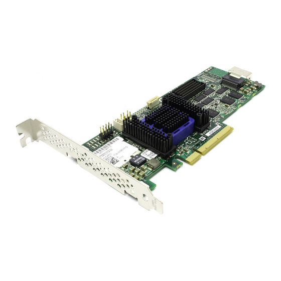
Adaptec 5085 Installation And User Manual

Adaptec 5085 Installation And User Manual

Serial attached scsi raid controllers
Hide thumbs Also See for 5085:
Table of Contents

Advertisement

Quick Links

Serial Attached SCSI RAID Controllers
Installation and User's Guide
PMC-Sierra Confidential — Preliminary Draft 5/18/11

Advertisement

Table of Contents
loading
Need help?

Need help?

Do you have a question about the 5085 and is the answer not in the manual?

Questions and answers

Subscribe to Our Youtube Channel

Summary of Contents for Adaptec 5085

  • Page 1 Serial Attached SCSI RAID Controllers Installation and User’s Guide PMC-Sierra Confidential — Preliminary Draft 5/18/11...
  • Page 2 Sierra, Inc. Trademarks PMC, PMC-Sierra, and Adaptec are registered trademarks of PMC-Sierra, Inc. “Adaptec by PMC” is a trademark of PMC-Sierra, Inc. Other product and company names mentioned herein may be trademarks of their respective owners. For a complete list of PMC-Sierra trademarks, see www.pmc-sierra.com/legal.
  • Page 3 Adaptec by PMC Product Support If you have questions about installing or using your Adaptec by PMC product, check this document first—you will find answers to most of your questions. If you need further assistance, use the support options listed below. To expedite your service, have your computer in front of you.
  • Page 4 ● Limited 3-Year Hardware Warranty 1. PMC-Sierra, Inc. (“PMC-Sierra”) warrants to the purchaser of this product that it will be free from defects in material and workmanship for a period of three (3) years from the date of purchase. If the product should become defective within the warranty period, PMC-Sierra, at its option, will repair or replace the product, or refund the purchaser’s purchase price for the product, provided it is delivered at the purchaser’s expense to an authorized PMC-Sierra service facility or to PMC-Sierra.
  • Page 5 UL Compliance Statement Adaptec by PMC products are tested and listed by Underwriters Laboratories, Inc. to UL 60950-1 Second Edition and IEC- 60950-1 Second Edition standards, file numbers E175975. Adaptec by PMC products are for use only with UL listed ITE.
  • Page 6 ● Korean Compliance (KCC) Statement Adaptec by PMC products are tested and certified by KCC: KCC-REM-KHK-ASR-6xx5 The above certification covers the following series: ASR-6805, ASR-6445, ASR-6405 ASR-6805E, ASR-6405E This equipment is home use (Class B) electromagnetic wave suitability equipment and to be used mainly at home and it can be used in all areas.
  • Page 7: Table Of Contents

    Adding a Battery Backup Module ..............19 Adding a Flash Backup Module ............... 19 Upgrading the Controller Firmware ..............19 About the Adaptec RAID 5085................. 20 About the Adaptec RAID 5405................. 21 About the Adaptec RAID 5445................. 22 About the Adaptec RAID 5805/5805Q ............23 About the Adaptec RAID 51245...............
  • Page 8: Contents

    Setting the Boot Controller ................52 Creating an Array....................52 Creating an Array with the ACU ............... 52 Creating an Array with Adaptec Storage Manager ........54 Making Your Array Bootable ................55 Installing the Driver and an Operating System Before You Begin....................
  • Page 9 Managing Your Storage Space About Adaptec Storage Manager ..............73 Installing Adaptec Storage Manager ............73 About the Adaptec RAID Controller Configuration Utility......73 About the Adaptec RAID Configuration Utility ..........74 About the Adaptec Flash Utility ............... 74 Which Utility Should I Use? ................74 10 Solving Problems Troubleshooting Checklist ................
  • Page 10 RAID 6 Arrays ....................94 RAID 60 Arrays ....................94 Selecting the Best RAID Level ................95 Using the Adaptec RAID Configuration Utility Introduction to the ARC Utility............... 97 Running the ARC Utility .................. 97 Navigating the ARC Utility ................ 97 Using the ACU to Create and Manage Arrays..........
  • Page 11 Controller LED and I2C Connector Quick Reference Adaptec RAID 5085 LED Connector Specification........115 Adaptec RAID 5405/5405Z LED and I2C Connector Specification .... 117 Adaptec RAID 5445/5445Z LED and I2C Connector Specification .... 118 Adaptec RAID 5805/5805Q/5805Z/5805ZQ LED and I2C Connector Specification ....................
  • Page 12 Terminology Used in this Guide.................... 13 How to Find More Information .................... 13 ™ ® This Installation and User’s Guide explains how to install your Adaptec by PMC RAID controller. It also describes the utilities included in your controller kit, and provides a basic overview of Serial Attached SCSI (SAS) and Redundant Array of Independent Disk (RAID) technology.
  • Page 13: About This Guide

    Your RAID Controller on page Terminology Used in this Guide Because you can use your Adaptec RAID controller to manage data storage in a variety of configurations, the generic term “storage space” is used to refer to controller(s) and disk drives being managed with Adaptec Storage Manager or the other utilities described in this guide.
  • Page 14 Kit Contents and System Requirements In this chapter... Kit Contents..........................15 System Requirements ......................15 This chapter lists the contents of your Adaptec RAID controller kit and the system requirements that must be met for you to successfully install and use your controller.
  • Page 15: Kit Contents And System Requirements

    Adaptec Storage Manager, ARCCONF command line utility, and documentation Cables (Not all kits contain cables. If your kit does, the type and quantity vary—for cable ● information about your controller, visit the Adaptec Web site at www.adaptec.com.) (Selected models only) Low-profile bracket ●...
  • Page 16 Chapter 2: Kit Contents and System Requirements ● 16-bit SVGA color monitor with a resolution of at least 800 x 600 ● DVD-ROM drive ● Floppy disk drive, USB flash drive, or CD burner, for creating driver disks and bootable ●...
  • Page 17 About the Adaptec RAID 6805 ....................35 About the Adaptec RAID 6405E.................... 36 About the Adaptec RAID 6805E.................... 37 This chapter provides an overview of the standard features on your Adaptec RAID controller, and describes the unique features of your controller.
  • Page 18: About Your Raid Controller

    Array-level Features Note: Not all features are supported by all controllers. For more information, refer to the Adaptec Storage Manager User’s Guide or online Help. Support for RAID 0, RAID 1, RAID 5, RAID 10, RAID 50, simple volumes, and spanned ●...
  • Page 19: Advanced Data Protection Suite

    Advanced Data Protection Suite Note: The following features are supported on Adaptec Series 5 and Series 6 controllers. Striped Mirrors are also supported on Series 2 and Series 6E controllers. Copyback Hot Spare—You can use this feature to move data from a hot spare back to its ●...
  • Page 20: About The Adaptec Raid 5085

    Chapter 3: About Your RAID Controller ● About the Adaptec RAID 5085 The Adaptec RAID 5085 is a SAS RAID controller with these features: Ext. Alarm Diagnostic Aggregate Activity LEDs Drive Activity Audible Alarm Mode 0 Flash LEDs connector Drive Activity LED...
  • Page 21: About The Adaptec Raid 5405

    Chapter 3: About Your RAID Controller ● About the Adaptec RAID 5405 The Adaptec RAID 5405 is a SAS RAID controller with these features: Drive Activity LED connectors for CN0 Drive Activity LEDs for CN0 Mode 0 Flash Diagnostic LEDs...
  • Page 22: About The Adaptec Raid 5445

    Chapter 3: About Your RAID Controller ● About the Adaptec RAID 5445 The Adaptec RAID 5445 is a SAS RAID controller with these features: Diagnostic LEDs Drive Activity CN1/CN0 (back of card) Status CN1/CN0 Mode 0 Flash connector Ext. Alarm...
  • Page 23: About The Adaptec Raid 5805/5805Q

    Chapter 3: About Your RAID Controller ● About the Adaptec RAID 5805/5805Q The Adaptec RAID 5805/5805Q is a SAS RAID controller with these features: Drive Activity LED connectors for CN0/CN1 Drive Activity LEDs for CN0/CN1 Mode 0 Flash Diagnostic LEDs...
  • Page 24: About The Adaptec Raid 51245

    Chapter 3: About Your RAID Controller ● About the Adaptec RAID 51245 The Adaptec RAID 51245 is a SAS RAID controller with these features: I2C, CN1 Mode 0 Flash I2C, CN0 I2C, CN2 Activity CN2 3 internal Activity mini-SAS CN0, CN1...
  • Page 25: About The Adaptec Raid 51645

    Chapter 3: About Your RAID Controller ● About the Adaptec RAID 51645 The Adaptec RAID 51645 is a SAS RAID controller with these features: I2C, CN1 Mode 0 Flash I2C, CN0 I2C, CN2 Activity CN2, CN3 I2C, CN3 4 internal...
  • Page 26: About The Adaptec Raid 52445

    Chapter 3: About Your RAID Controller ● About the Adaptec RAID 52445 The Adaptec RAID 52445 is a SAS RAID controller with these features: Mode 0 Flash connector I2C, CN2 Activity CN2, CN3 I2C, CN1 I2C, CN3 I2C, CN0 I2C, CN4...
  • Page 27: About The Adaptec Raid 5405Z

    Chapter 3: About Your RAID Controller ● About the Adaptec RAID 5405Z The Adaptec RAID 5405Z is a SAS RAID controller with these features: Drive Activity LED connectors for CN0 Drive Activity LEDs for CN0 I2C connector for CN0 Ext. Alarm connector...
  • Page 28: About The Adaptec Raid 5445Z

    Chapter 3: About Your RAID Controller ● About the Adaptec RAID 5445Z The Adaptec RAID 5445Z is a SAS RAID controller with these features: Drive Activity LED connectors for CN0/CN1 Drive Activity LEDs for CN0/CN1 I2C connectors for CN0/CN1 Ext. Alarm connector...
  • Page 29: About The Adaptec Raid 5805Z/5805Zq

    Chapter 3: About Your RAID Controller ● About the Adaptec RAID 5805Z/5805ZQ The Adaptec RAID 5805Z/5805ZQ is a SAS RAID controller with these features: Drive Activity LED connectors for CN0/CN1 Drive Activity LEDs for CN0/CN1 I2C connectors for CN0/CN1 Ext. Alarm connector...
  • Page 30: About The Adaptec Raid 2045

    Chapter 3: About Your RAID Controller ● About the Adaptec RAID 2045 The Adaptec RAID 2045 is a SAS RAID controller with these features: Aggregate Activity Mode 0 Flash connector 1 external mini- PCIe x8 connector SAS connector Mounting bracket...
  • Page 31: About The Adaptec Raid 2405/2405Q

    Chapter 3: About Your RAID Controller ● About the Adaptec RAID 2405/2405Q The Adaptec RAID 2405/2405Q is a SAS RAID controller with these features: Activity connector for CN0 Aggregate Activity Mode 0 Flash connector Internal mini-SAS connector CN0 I2C, CN0...
  • Page 32: About The Adaptec Raid 2805

    Chapter 3: About Your RAID Controller ● About the Adaptec RAID 2805 The Adaptec RAID 2805 is a SAS RAID controller with these features: Activity connector for CN0/CN1 Aggregate Activity Mode 0 Flash connector Internal mini-SAS connector CN1 Internal mini-SAS...
  • Page 33: About The Adaptec Raid 6405

    Chapter 3: About Your RAID Controller ● About the Adaptec RAID 6405 The Adaptec RAID 6405 is a SAS RAID controller with these features: Activity connector for CN0 I2C connector for CN0 Ext. Alarm connector Activity LEDs Aggregate Activity (back of card)
  • Page 34: About The Adaptec Raid 6445

    Chapter 3: About Your RAID Controller ● About the Adaptec RAID 6445 The Adaptec RAID 6445 is a SAS RAID controller with these features: Activity connector for CN0 I2C connector for CN0 Ext. Alarm connector Drive Activity LEDs Aggregate Activity...
  • Page 35: About The Adaptec Raid 6805

    Chapter 3: About Your RAID Controller ● About the Adaptec RAID 6805 The Adaptec RAID 6805 is a SAS RAID controller with these features: Activity connector for CN0/CN1 I2C connector for CN1 I2C connector for CN0 Ext. Alarm connector Drive Activity LEDs...
  • Page 36: About The Adaptec Raid 6405E

    Chapter 3: About Your RAID Controller ● About the Adaptec RAID 6405E The Adaptec RAID 6405E is a SAS RAID controller with these features: Activity connector for CN0 HDA mode connector Ext. Alarm connector Aggregate Activity PCIe x1 connector Internal mini-SAS...
  • Page 37: About The Adaptec Raid 6805E

    Chapter 3: About Your RAID Controller ● About the Adaptec RAID 6805E The Adaptec RAID 6805E is a SAS RAID controller with these features: Activity connector for CN0/CN1 HDA mode connector Ext. Alarm connector Aggregate Activity 2 internal mini-SAS connectors...
  • Page 38 This chapter provides the basic information you need to set up your disk drives and arrays the way you want them. It also describes the options you have for installing your Adaptec RAID controller and disk drives, and creating arrays for data storage.
  • Page 39: Getting Started

    Chapter 4: Getting Started ● Choosing a RAID Level This section provides a brief overview of the RAID levels supported by your Adaptec RAID controller, including the minimum and maximum number of disk drives required by each. Note: Before you begin, familiarize yourself with your controller’s physical features and the...
  • Page 40: Selecting Disk Drives And Cables

    For more information about arrays, refer to the Adaptec Storage Manager User’s Guide or online Help. For more information about compatible disk drives, refer to the Adaptec Web site at www.adaptec.com/compatibility.
  • Page 41: Installation Options

    Adaptec Web site at www.adaptec.com. Installation Options When you install your Adaptec RAID controller, you can choose to create a bootable array and then install your operating system and the controller driver on that array. Alternatively, you can complete a standard installation, where the controller driver is installed...
  • Page 42: Basic Installation Steps

    52). Install your operating system and the controller driver (see page 56.) Install Adaptec Storage Manager and begin to manage your data storage (see page 72). Installing on an Existing Operating System Install and connect your controller and internal disk drives (see page 43).
  • Page 43 Installing the Controller......................44 Connecting Disk Drives to Your Controllers ................ 46 Connecting External Devices....................50 Next Steps ..........................50 This chapter explains how to install your Adaptec RAID controller, and how to install and connect internal and external disk drives.
  • Page 44: Installing The Controller And Disk Drives

    Handle the controller by its bracket or edges only. Installing the Controller This section describes how to install your Adaptec RAID controller into your computer cabinet. Adaptec RAID controllers come in two basic configurations: standard and zero maintenance cache protection with batteryless backup. Follow one of these sets of instructions: To install a standard series Adaptec RAID controller (without zero maintenance cache ●...
  • Page 45: Installing A Raid Controller With Zero Maintenance Cache Protection

    Do not attempt to connect a Battery Backup Module (see page 19) to an Adaptec RAID controller with Zero Maintenance Cache Protection. The battery module can overheat and may even explode! Turn off your computer and disconnect the power cord. Open the cabinet, following the manufacturer’s instructions.
  • Page 46: Connecting Disk Drives To Your Controllers

    Connecting External Devices on page Connecting Disk Drives to Your Controllers You can connect SAS disk drives, SATA disk drives, SATA and SAS Solid State Drives (SSD), and Adaptec MaxIQ Solid State Drives to your SAS RAID controller. (See www.adaptec.com/ compatibility for a list of compatible disk drives.) There are no jumpers or switches to set...
  • Page 47: Connecting To A System Backplane

    Chapter 5: Installing the Controller and Disk Drives ● Use internal SAS or mini-SAS cables to attach the disk drives to the controller, as shown in the following example. SAS/SATA disk drives or SSDs internal x4 mini-SAS connectors mini-SAS to SATA fan-out cable Single-port connector Note: SAS fan-out cables are also available with an additional sideband (SFF-8448) cable...
  • Page 48: Connecting Maxiq Solid State Drives And Other Ssds

    Connecting MaxIQ Solid State Drives and other SSDs To connect an Adaptec MaxIQ Solid State Drive or other SSD to your controller, use a direct- attached connection or a backplane connection. If your server does not have a standard 2.5- inch drive tray, you must use a bracket/SLED which enables the SSD to fit properly (not included with MaxIQ SSD kit).
  • Page 49 17). Note: The following steps use an Adaptec MaxIQ SSD as an example but the procedure is suitable for any compatible SSD. Install your Adaptec MaxIQ SSDs in your server. For servers with a standard 2.5-inch drive tray, install the SSD directly into the tray. If your server does not have a standard 2.5-inch drive tray, use a bracket or adapter which enables it to fit properly.
  • Page 50: Connecting External Devices

    Use high-quality cables to connect your controller to your external device(s), such as disk drives or disk drive enclosures. We recommend using only Adaptec cables. For more information or to purchase cables, visit the Adaptec Web site at www.adaptec.com. Next Steps...
  • Page 51 Setting the Boot Controller....................52 Creating an Array ........................52 Making Your Array Bootable ....................55 This chapter explains how to set your Adaptec controller to be the boot controller, and how to create a bootable array. Note: If you are completing a standard installation onto an existing operating system, you don’t have to complete this task.
  • Page 52: Creating A Bootable Array

    Note: We recommend that you not combine SAS and SATA disk drives within the same array. Adaptec Storage Manager generates a warning if you try to create a logical drive using a combination of SAS and SATA disk drives. See page 81 for more information.
  • Page 53 Chapter 6: Creating a Bootable Array ● Select Initialize Drives, then press Enter. Select at least three disk drives for the array, press Insert for each selected disk drive, then press Enter. Caution: During initialization, all data is deleted from the disk. Before continuing, back up any data you want to keep.
  • Page 54: Creating An Array With Adaptec Storage Manager

    Chapter 6: Creating a Bootable Array ● Creating an Array with Adaptec Storage Manager This section describes how to use the Adaptec Storage Manager configuration wizard to build a RAID 5 array. Note: You will need the Adaptec RAID Controller Installation DVD to complete this task.
  • Page 55: Making Your Array Bootable

    13). In this example, Adaptec Storage Manager has used thirteen equal-sized disk drives to automatically create one logical drive with RAID 5 and a hot spare. To exclude specific disk drives from the logical drive, specify a size for the logical drive, or to make other changes to the configuration, click Modify logical devices.
  • Page 56 Installing with UnixWare ....................... 63 Installing with Solaris......................63 Installing with VMware ......................63 Installing with FreeBSD ......................64 This chapter explains how to install your Adaptec RAID controller driver and an operating system on a bootable array (see page 51).
  • Page 57: Installing The Driver And An Operating System

    Note: Not all operating systems are supported on all controllers. For up-to-date operating system version support, visit the Adaptec Web Site at www.adaptec.com. From the main menu select Support>Knowledgebase>Find Answers. Select your controller type and OS support to generate a list of supported operating systems and to download the latest drivers.
  • Page 58: Installing With Windows

    Follow the on-screen instructions to begin the Windows installation. When prompted to specify a location for Windows, select Load Driver. Insert the Adaptec RAID Controller Installation DVD, browse to the driver location, then click OK. When the Adaptec driver is found, press Next.
  • Page 59: Installing With Red Hat Linux 5

    You will need your Red Hat 6 or Fedora Installation CD to complete this task. You must have root privileges to install the driver image. To install the Adaptec RAID controller driver while installing Red Hat 6 or Fedora Linux: Insert the Red Hat or Fedora Installation CD.
  • Page 60: Installing With Suse Linux

    You will need your Debian or Ubuntu Installation CD and a USB stick to complete this task. You must have root privileges to install the driver image. To install the Adaptec RAID controller driver while installing Debian or Ubuntu Linux: Create the driver disk:...
  • Page 61 CTRL+ALT+F2 to switch to the console. Do not reboot! Note: Adaptec drivers for Debian and Ubuntu do not support LVM partitioning! Be sure to select 'Guided - use entire disk', NOT 'Guided - use entire disk and set up LVM'.
  • Page 62: Installing With Openserver

    Installing with OpenServer Note: You will need your OpenServer Installation CD to complete this task. To install the Adaptec RAID controller driver when installing OpenServer: Insert the OpenServer Installation CD. Restart your computer. Follow the on-screen instructions to begin the OpenServer installation.
  • Page 63: Installing With Unixware

    Installing with UnixWare Note: You will need your UnixWare Installation CD to complete this task. To install the Adaptec RAID controller driver when installing UnixWare: Insert the UnixWare Installation CD. Restart your computer. Follow the on-screen instructions to begin the UnixWare installation.
  • Page 64: Installing With Freebsd

    You can ignore this message. Note: The Adaptec Storage Manager GUI is not supported on VMware. To create and manage arrays, you must connect to the VMware machine from a remote GUI or use ARCCONF. See page 74 for more information.
  • Page 65 Chapter 7: Installing the Driver and an Operating System ● Complete the FreeBSD installation, following the instructions included with your operating system. Reboot your computer, then remove the driver disk. Repeat Steps through the first time you boot the operating system to load the drivers again.
  • Page 66 Installing on UnixWare ......................69 Installing on Solaris........................ 70 Installing on VMware......................70 Installing on FreeBSD ......................71 This chapter explains how to install your Adaptec RAID controller driver. Note: To install the driver while you’re installing an operating system, see page...
  • Page 67: Installing The Driver On An Existing Operating System

    Chapter 8: Installing the Driver on an Existing Operating System ● Before You Begin Before you begin, install and connect your Adaptec RAID controller and internal disk drives (see page 43). You must also create a driver disk before you begin installing the controller driver.
  • Page 68: Installing On Windows

    Chapter 8: Installing the Driver on an Existing Operating System ● Installing on Windows Follow the instructions in this section for your version of Windows. Installing on Windows Server 2003 To install the driver on Windows: Start or restart Windows. The Found New Hardware Wizard opens and searches for the driver.
  • Page 69: Installing On Debian Or Ubuntu Linux

    Chapter 8: Installing the Driver on an Existing Operating System ● Installing on Debian or Ubuntu Linux Note: You must have root privileges to install the driver image. For Debian, the Linux su command is sufficient. For Ubuntu, you may need to create the root account and password. Enter these commands: sudo bash;...
  • Page 70: Installing On Solaris

    Check for any pre-existing Adaptec driver by performing a in a terminal pkginfo SUNWaac window. If there is no pre-existing Adaptec driver on your computer, continue with Step If an Adaptec driver is already installed on your computer, perform a pkgrm SUNWaac remove it.
  • Page 71: Installing On Freebsd

    Remove the RAID Controller Installation DVD, then reboot your computer. Note: Currently, the Adaptec Storage Manager GUI is not supported on VMware. To create and manage arrays, you must connect to the VMware machine from a remote GUI or use the ARCCONF utility.
  • Page 72 About the Adaptec Flash Utility .................... 74 Which Utility Should I Use? ....................74 Once you have installed your Adaptec RAID controller, disk drives (or other devices), and device driver, you can begin to build and manage your storage space.
  • Page 73: Managing Your Storage Space

    Adaptec Storage Manager is a full-featured software application that helps you build a storage space for your online data, using Adaptec RAID controllers and disk drives. With Adaptec Storage Manager, you can group disk drives into logical drives and build in redundancy to protect your data and improve system performance.
  • Page 74: About The Adaptec Raid Configuration Utility

    About the Adaptec Flash Utility The Adaptec Flash Utility (AFU) is a text-based DOS utility that you can use to update, save, or verify your RAID controller’s firmware BIOS and Non-Volatile Random Access Memory (NVRAM).
  • Page 75: Solving Problems

    Solving Problems In this chapter... Troubleshooting Checklist ..................... 76 Silencing the Alarm ........................ 76 Recovering from a Disk Drive Failure ................... 77 Resetting the Controller......................78 This chapter provides basic troubleshooting information and solutions for solving controller problems.
  • Page 76: Troubleshooting Checklist

    Monitoring Disk Drives Status You can use the ‘blink’ feature of Adaptec Storage Manager to monitor the status of your SAS and SATA disk drives. When you blink a specific disk drive or set of disk drives, the LED(s) on the selected disk drives flash.
  • Page 77: Recovering From A Disk Drive Failure

    Make sure that the new disk drive is equal or greater in size than the failed disk drive. Then, if necessary, use Adaptec Storage Manager to rebuild the array. For instructions, refer to the Adaptec Storage Manager User’s Guide or online Help.
  • Page 78: Disk Drive Failure In A Raid 0 Array

    Adaptec Storage Manager. Resetting the Controller This section explains how to reset (or Mode 0 flash) your Adaptec RAID controller. You may want to do this if the controller becomes inoperable, or if a firmware upgrade is unsuccessful.
  • Page 79 Disconnect all cables from the controller, then attach a shorting jumper to the Mode 0 flash connector. Note: To locate the Mode 0 flash connector on your Adaptec RAID controller, see the figures in About Your RAID Controller on page 17.
  • Page 80 Introduction to SAS In this appendix... Terminology Used in This Chapter ..................81 What is SAS? ........................... 81 How Do SAS Devices Communicate? ................... 82 What’s a Phy? .......................... 82 What’s a SAS Port?........................83 What’s a SAS Address?......................83 What’s a SAS Connector? .......................
  • Page 81: Terminology Used In This Chapter

    Appendix A: Introduction to SAS ● Terminology Used in This Chapter For convenience, SAS HBAs and SAS RAID controllers are referred to generically in this chapter as SAS cards. HBAs, RAID controllers, disk drives, and external disk drive enclosures are referred to as end devices and expanders are referred to as expander devices. For convenience, this chapter refers to end devices and expander devices collectively as SAS devices.
  • Page 82: How Do Sas Devices Communicate

    Appendix A: Introduction to SAS ● How Do SAS Devices Communicate? SAS devices communicate with each other through links. A link is a physical connection between two phys. As shown in the following figure, SAS devices contain ports (see page 83), ports contain phys, and each phy contains one transmitter and one receiver—one transceiver.
  • Page 83: What's A Sas Port

    Appendix A: Introduction to SAS ● What’s a SAS Port? Note: Because the physical link between SAS devices is from phy to phy, rather than port to port, a “port” is more of a virtual concept, different from what is normally considered a port on other types of RAID controllers and storage devices.
  • Page 84: How Are Disk Drives Identified In Sas

    RAID controller Activity LED connections and locations. Once you have connected to a backplane, use Adaptec Storage Manager to manage your disk drives. For more information, refer to the Adaptec Storage Manager User’s Guide on the RAID Controller Installation DVD.
  • Page 85: Sas Expander Connections

    Appendix A: Introduction to SAS ● Some backplanes support daisy-chain expansion to other backplanes. For example, you can daisy-chain (connect one to the next) up to nine Adaptec S50 enclosures to a single SAS card in a host system. SAS Expander Connections A SAS expander device literally expands the number of end devices that you can connect together.
  • Page 86: How Is Sas Different From Parallel Scsi

    Appendix A: Introduction to SAS ● How is SAS Different from Parallel SCSI? In summary, although SAS and parallel SCSI both use the SCSI command set, how they move data from one place to another is very different. To support point-to-point serial data transport, SAS introduces new types of connectors, cables, connection options, and terminology.
  • Page 87 This appendix describes the RAID levels supported by your Adaptec RAID controller, and provides a basic overview of each to help you select the best level of protection for your data...
  • Page 88: B Understanding Raid

    Appendix B: Understanding RAID ● Understanding Drive Segments A drive segment is a disk drive or portion of a disk drive that is used to create an array. A disk drive can include both RAID segments (segments that are part of an array) and available segments.
  • Page 89: Raid 1 Arrays

    Appendix B: Understanding RAID ● RAID 1 Arrays A RAID 1 array is built from two disk drives, where one disk drive is a mirror of the other (the same data is stored on each disk drive). Compared to independent disk drives, RAID 1 arrays provide improved performance, with twice the read rate and an equal write rate of single disks.
  • Page 90: Raid 10 Arrays

    Appendix B: Understanding RAID ● RAID 10 Arrays A RAID 10 array is built from two or more equal-sized RAID 1 arrays. Data in a RAID 10 array is both striped and mirrored. Mirroring provides data protection, and striping improves performance.
  • Page 91: Raid 5 Arrays

    Appendix B: Understanding RAID ● RAID 5 Arrays A RAID 5 array is built from a minimum of three disk drives, and uses data striping and parity data to provide redundancy. Parity data provides data protection, and striping improves performance. Parity data is an error-correcting redundancy that’s used to re-create data if a disk drive fails.
  • Page 92: Raid 5Ee Arrays

    Appendix B: Understanding RAID ● RAID 5EE Arrays A RAID 5EE array—also known as a hot space—is similar to a RAID 5 array except that it includes a distributed spare drive and must be built from a minimum of four disk drives. Unlike a hot spare, a distributed spare is striped evenly across the disk drives with the stored data and parity data, and can’t be shared with other logical disk drives.
  • Page 93: Raid 50 Arrays

    Appendix B: Understanding RAID ● RAID 50 Arrays A RAID 50 array is built from six to forty-eight disk drives configured as two or more RAID 5 arrays, and stripes stored data and parity data across all disk drives in both RAID 5 arrays. (For more information, see RAID 5 Arrays on page 91.)
  • Page 94: Raid 6 Arrays

    Appendix B: Understanding RAID ● RAID 6 Arrays A RAID 6 array—also known as dual drive failure protection—is similar to a RAID 5 array because it uses data striping and parity data to provide redundancy. However, RAID 6 arrays include two independent sets of parity data instead of one. Both sets of parity data are striped separately across all disk drives in the array.
  • Page 95: Selecting The Best Raid Level

    Appendix B: Understanding RAID ● Selecting the Best RAID Level Use this table to select the RAID levels that are most appropriate for the logical drives on your storage space, based on the number of available disk drives and your requirements for performance and reliability.
  • Page 96 Locating Disk Drives ......................104 Identifying Disk Drives ......................105 Viewing the Event Log ......................106 The Adaptec RAID Configuration (ARC) utility is a BIOS-based utility that you can use to create and manage controllers, disk drives and other devices, and arrays. Note: We recommend that only advanced users familiar with working in a computer BIOS use utility tools.
  • Page 97: Introduction To The Arc Utility

    104). ● Running the ARC Utility If your Adaptec controller is connected to a RAID enclosure, power on your enclosure (or enclosures) before you power on your computer. Start or restart your computer. When prompted, press Ctrl+A. During boot up, if your system has insufficient memory this message displays: “Adaptec RAID Configuration Utility will load after, system initialization.
  • Page 98: Managing Existing Arrays

    Appendix C: Using the Adaptec RAID Configuration Utility ● Managing Existing Arrays To view or modify existing arrays, select Manage Arrays from the main ACU menu. From the Manage Arrays menu, you can: View the properties of an array. ●...
  • Page 99: Initializing Disk Drives

    Appendix C: Using the Adaptec RAID Configuration Utility ● Option Description Power Off Drive After The duration of inactive state of the array/drive after which it is powered off. This is an optional setting. Note: Power Off Drive After duration should be greater than Slow Down Drive After Duration.
  • Page 100: Secure Erasing Disk Drives

    (see page 104) instead, or clear it using Adaptec Storage Manager—both options take much less time than the secure erase option. To begin a secure erase, select Secure Erase from the main ACU menu, then select Y (yes). To return to the main ACU menu once the secure erase has begun, press Esc.
  • Page 101: Managing Existing Jbods

    State Drives installed on the RAID controllers in your system. For a list of MaxIQ-compatible SSDs, refer to the Adaptec Web site at www.adaptec.com/compatibility. To add an SSD to the MaxIQ pool or to remove an SSD from the MaxIQ pool:...
  • Page 102: Opening Serialselect

    When set to Enable All, write cache is enabled on all disk drives on the controller. (Enabling the write cache overrides any individual drive settings in Adaptec Storage Manager.) When set to Disable All, write cache is not used on the disk drives. When set to Drive Specific, write cache is enabled/disabled on a per-drive basis in Adaptec Storage Manager.
  • Page 103 Appendix C: Using the Adaptec RAID Configuration Utility ● Option Description Physical Drives Display When enabled, connected disk drives are displayed during system Power During POST On Self Test (POST). Displaying the disk drives adds a few seconds to the overall POST time. Default is disabled.
  • Page 104: Formatting And Verifying Disk Drives

    The data transfer rate between the controller and devices. The default setting is Auto, which allows the SAS card to adjust the data transfer rate, as needed. For low-port 5-series RAID controllers (5085, 5405), you can set the PHY rate to 1.5Gb/second or 3.0Gb/second (the maximum rate).
  • Page 105: Identifying Disk Drives

    Appendix C: Using the Adaptec RAID Configuration Utility ● Select the disk drive you want, then press Enter. Select Identify Drive, then press Enter. When you have finished locating your disk drive, press any key to stop the blinking. Identifying Disk Drives You can identify disk drives by viewing the list of disk drives on your system.
  • Page 106: Viewing The Event Log

    Appendix C: Using the Adaptec RAID Configuration Utility ● Viewing the Event Log The BIOS-based event log records all firmware events, such as configuration changes, array creation, and boot activity. Some events are not stored indefinitely—the event log is cleared of any non-persistent events each time you restart your computer;...
  • Page 107 Updating the Flash Using the AFU Command Line ............113 This chapter describes how to use the Adaptec Flash Utility (AFU), a text-based DOS utility that you can use to update, save, or verify the RAID controller’s firmware BIOS and NVRAM.
  • Page 108: System Requirements

    The RAID Controller Installation DVD—Includes the AFU executable (AFU.exe) and a ● separate flash image. The flash image may comprise multiple User Flash Image (UFI) files. The Adaptec Web site—Download a new firmware file to get the most recent version of ● firmware/BIOS and AFU.
  • Page 109: Creating The Firmware Update Disks

    Note: Most controller model numbers have a suffix (for example Adaptec RAID 3405). Check that the .ufi file is the correct file for your controller before copying. If using floppy disks, copy each additional Axxxx0x.ufi file to a separate floppy disk. (Some RAID controllers have two UFI files;...
  • Page 110: Running The Afu From The Command Line

    Appendix D: Using the Adaptec Flash Utility ● Complete the flash operation and restart your computer before trying to use the RAID controller again. (You can not use your RAID controller while you are updating its flash.) The AFU processes the selected command, prompts you to insert additional floppy disks as needed, and reports either success or an error message code.
  • Page 111 (c)Adaptec Inc. 1999–2005. All Rights Reserved. Updating Controller 0 (Adaptec RAID 31205) Reading flash image file (Build 5749) AFU is about to update firmware on controllers Adaptec RAID 51645 ***PLEASE DO NOT REBOOT THE SYSTEM DURING THE UPDATE*** This might take a few minutes.
  • Page 112 A:\> AFU VERSION /C 0 Adaptec Flash Utility V4.0-0 B5749 (c)Adaptec Inc. 1999–2005. All Rights Reserved. Version Information for Controller #0 (Adaptec RAID 51645) ROM: Build 5748 [VALID] Fri Sep 27 13:28:40 EDT 2005 A:\> AFU VERSION /C ALL Help Displays a summary of AFU functions and command switches.
  • Page 113: Updating The Flash Using The Afu Command Line

    ● AFU UPDATE /C <cont_number_a>,<cont_number_b> Where <controller_number_a> and <controller_number_b> are the numbers of the Adaptec RAID controllers whose firmware you are updating. For example, to upgrade controllers 0, 2, and 3, type AFU UPDATE /C 0, 2, 3 To update all RAID controllers simultaneously: ●...
  • Page 114 Adaptec RAID 6405/6445 LED and I2C Connector Specification ........131 Adaptec RAID 6805 LED and I2C Connector Specification..........133 Adaptec RAID 6405E LED Connector Specification............134 Adaptec RAID 6805E LED Connector Specification............135 This chapter provides a reference guide for Adaptec RAID controllers of Activity LED and I2C connectors.
  • Page 115: Adaptec Raid 5085 Led Connector Specification

    Appendix E: Controller LED and I2C Connector Quick Reference ● Adaptec RAID 5085 LED Connector Specification 2249100-R ASR-5085/512MB RoHS SGL Adaptec RAID 5085 Activity LED Header Connector: Molex 10-89-7162 or equivalent ● Activity LED Header Mating Cable Connector: Molex 22-55-2161 or equivalent ● 22-55-2161...
  • Page 116 J12: J12 Pin Number Signal Description ~2kHz Square Wave Open collector transistor +3.3V Adaptec RAID 5085 Status LED Board Connector: Molex 10-89-7162 or equivalent ● Status LED Mating Cable Connector: Molex 22-55-2161 or equivalent ● J14: 22-55-2161 J14 Pin Number...
  • Page 117: Adaptec Raid 5405/5405Z Led And I2C Connector Specification

    Specification 2258100-R ASR-5405 RoHS KIT 2258200-R ASR-5405 RoHS Single 2266800-R ASR-5405Z RoHS Single Adaptec RAID 5405/5405Z Activity LED Header Connector: Molex 10-89-7162 or ● equivalent Activity LED Header Mating Cable Connector: Molex 22-55-2161 or equivalent ● 22-55-2161 J2 Pin Number...
  • Page 118: Adaptec Raid 5445/5445Z Led And I2C Connector Specification

    Activity LED Header Mating Cable Connector: Molex 22-55-2161 or equivalent ● Note: For Adaptec RAID 5445, header J2 is a 16-pin connector (pins 1-16). For Adaptec RAID 5445Z, header J2 is an 8-pin connector (pins 1-8 only). 22-55-2161 J2 Pin Number...
  • Page 119 I2C Mating Cable Connector: Molex 22-43-3030 or equivalent ● J4 Pin Number Signal I2C Clock Ground I2C Data Adaptec RAID 5445 Status LED Board Connector: Molex 10-89-7162 or equivalent ● Status LED Mating Cable Connector: Molex 22-55-2161 or equivalent ●...
  • Page 120: Adaptec Raid 5805/5805Q/5805Z/5805Zq Led And I2C Connector Specification

    2266900-R ASR-5805Z RoHS Single 2268500-R ASR-5805Q RoHS Single 2268600-R ASR-5805ZQ RoHS Single Adaptec RAID 5805/5805Q/5805Z/5805ZQ Activity LED Header Connector: Molex 10- ● 89-7162 or equivalent Activity LED Header Mating Cable Connector: Molex 22-55-2161 or equivalent ● 22-55-2161 J2 Pin Number...
  • Page 121 J12 Pin Number Signal Description ~2kHz Square Wave Open collector transistor +3.3V — Adaptec RAID 5805/5805Q/5805Z/5805ZQ I2C CN0 Board Connector: Molex 22-43- ● 6030 or equivalent I2C Mating Cable Connector: Molex 22-43-3030 or equivalent ● J4 Pin Number Signal I2C Clock...
  • Page 122: Adaptec Raid 51245 Led And I2C Connector Specification

    Adaptec RAID 51245 LED and I2C Connector Specification 2268200-R ASR-51245 RoHS Kit 2268300-R ASR-51245 RoHS Single Adaptec RAID 51245 Activity LED Header Connector for CN0/CN1: Molex 10-89-7162 ● or equivalent Activity LED Header Mating Cable Connector: Molex 22-55-2161 or equivalent ●...
  • Page 123 ACTIVITY CN0, LANE 2 LED Cathode +3.3V LED Anode ACTIVITY CN0, LANE 3 LED Cathode Adaptec RAID 51245 Activity LED Board Connector for CN2: Molex 10-89-7162 or ● equivalent Activity LED Mating Cable Connector: Molex 22-55-2161 or equivalent ● 22-55-2161...
  • Page 124: Adaptec Raid 51645 Led And I2C Connector Specification

    Appendix E: Controller LED and I2C Connector Quick Reference ● Adaptec RAID 51245 Aggregate Activity LED Board Connector: Molex 22-28-4023 or ● equivalent Aggregate LED Mating Cable Connector: Molex 50-57-9002 or equivalent ● J10: J10 Pin Number Signal Description ACTIVITY LED Cathode +3.3V...
  • Page 125 ACTIVITY CN0, LANE 2 LED Cathode +3.3V LED Anode ACTIVITY CN0, LANE 3 LED Cathode Adaptec RAID 51645 Activity LED Board Connector for CN2/CN3: Molex 10-89-7162 or ● equivalent Activity LED Mating Cable Connector: Molex 22-55-2161 or equivalent ● 22-55-2161...
  • Page 126: Adaptec Raid 52445 Led And I2C Connector Specification

    Adaptec RAID 52445 LED and I2C Connector Specification 2258800-R ASR-52445 RoHS Kit 2258700-R ASR-52445 RoHS Single Adaptec RAID 52445 Activity LED Header Connector for CN0/CN1: Molex 10-89-7162 ● or equivalent Activity LED Header Mating Cable Connector: Molex 22-55-2161 or equivalent ●...
  • Page 127 ACTIVITY CN0, LANE 2 LED Cathode +3.3V LED Anode ACTIVITY CN0, LANE 3 LED Cathode Adaptec RAID 52445 Activity LED Board Connector for CN2/CN3: Molex 10-89-7162 or ● equivalent Activity LED Mating Cable Connector: Molex 22-55-2161 or equivalent ● 22-55-2161...
  • Page 128 ACTIVITY CN5, LANE 2 LED Cathode +3.3V LED Anode ACTIVITY CN5, LANE 3 LED Cathode Adaptec RAID 52445 Aggregate Activity LED Board Connector: Molex 22-28-4023 or ● equivalent Aggregate LED Mating Cable Connector: Molex 50-57-9002 or equivalent ● J10: J10 Pin Number...
  • Page 129: Adaptec Raid 2045 Led Connector Specification

    Appendix E: Controller LED and I2C Connector Quick Reference ● Adaptec RAID 2045 LED Connector Specification 2260300-R ASR-2045 RoHS SGL Adaptec RAID 2045 Aggregate Activity LED Board Connector: Molex 22-28-4023 or ● equivalent Aggregate LED Mating Cable Connector: Molex 50-57-9002 or equivalent ●...
  • Page 130: Adaptec Raid 2805 Led And I2C Connector Specification

    Adaptec RAID 2805 LED and I2C Connector Specification 2269600-R ASR-2805 RoHS KIT 2269500-R ASR-2805 RoHS SGL Adaptec RAID 2805 Activity LED Header Connector: Molex 10-89-7162 or equivalent ● Activity LED Header Mating Cable Connector: Molex 22-55-2161 or equivalent ● 22-55-2161...
  • Page 131: Adaptec Raid 6405/6445 Led And I2C Connector Specification

    Appendix E: Controller LED and I2C Connector Quick Reference ● Adaptec RAID 2805 Aggregate Activity LED Board Connector: Molex 22-28-4023 or ● equivalent Aggregate LED Mating Cable Connector: Molex 50-57-9002 or equivalent ● J1 Pin Number Signal Description ACTIVITY LED Cathode +3.3V...
  • Page 132 J12 Pin Number Signal Description ~2kHz Square Wave Open collector transistor +3.3V — Adaptec RAID 6405/6445 I2C CN0 Board Connector: Molex 22-43-6030 or equivalent ● I2C Mating Cable Connector: Molex 22-43-3030 or equivalent ● J4 Pin Number Signal I2C Clock, CN0...
  • Page 133: Adaptec Raid 6805 Led And I2C Connector Specification

    Adaptec RAID 6805 LED and I2C Connector Specification 2271200-R ASR-6805 Kit 2270100-R ASR-6805 SGL Adaptec RAID 6805 Activity LED Header Connector: Molex 22-43-6030 or equivalent ● Activity LED Header Mating Cable Connector: Molex 22-55-2161 or equivalent ● 22-55-2161 J2 Pin Number...
  • Page 134: Adaptec Raid 6405E Led Connector Specification

    J12 Pin Number Signal Description ~2kHz Square Wave Open collector transistor +3.3V — Adaptec RAID 6805 I2C CN0 Board Connector: Molex 22-43-6030 or equivalent ● I2C Mating Cable Connector: Molex 22-43-3030 or equivalent ● J4 Pin Number Signal I2C Clock, CN0...
  • Page 135: Adaptec Raid 6805E Led Connector Specification

    Appendix E: Controller LED and I2C Connector Quick Reference ● Adaptec RAID 6405E Aggregate Activity LED Board Connector: Molex 22-28-4023 or ● equivalent Aggregate LED Mating Cable Connector: Molex 50-57-9002 or equivalent ● J1 Pin Number Signal Description ACTIVITY LED Cathode +3.3V...
  • Page 136 Description Pin Number +3.3V LED Anode ACTIVITY CN1, LANE 3 LED Cathode Adaptec RAID 6805E Aggregate Activity LED Board Connector: Molex 22-28-4023 or ● equivalent Aggregate LED Mating Cable Connector: Molex 50-57-9002 or equivalent ● J1 Pin Number Signal Description...
  • Page 137: F Safety Information

    Put the controller down only on an antistatic surface such as the bag supplied in your kit. ● If you are returning the controller to Adaptec by PMC Product Support, put it back in its ● antistatic bag immediately.
  • Page 138 Technical Specifications In this appendix... Environmental Specifications....................139 DC Power Requirements...................... 139 Current Requirements......................139...
  • Page 139: G Technical Specifications

    Appendix G: Technical Specifications ● Environmental Specifications Note: Adaptec RAID controllers require adequate airflow to operate reliably. The recommended airflow is 200 LFM (linear feet per minute). Forced airflow is recommended. Ambient temperature with forced airflow 0 °C to 55 ° C 0 °C to 40 °...
  • Page 140 Adaptec customer support Automatic Failover setting Adaptec Flash Utility. See AFU Adaptec RAID Configuration utility Adaptec RAID Controller Configuration utility. See backplane connections ARCCONF battery backup module Adaptec Storage Manager batteryless backup creating arrays installing boards.
  • Page 141 Index ● Array Background Consistency Check setting RAID 0 arrays 102, with hot spare without hot spare Array-based BBS Support setting formatting array-level features identifying Automatic Failover setting initializing CD-ROM Boot Support setting recovering from failure connecting disk drives rescanning connecting external devices SAS identifiers CRC Checking setting...
  • Page 142 Index ● floppy disks for firmware update installing formatting disk drives mini-SAS FreeBSD direct connection driver installation enclosure cable OS installation internal cable overview SAS to SATA cable mirroring hard disk, hard disk drive, hard drive. See disk drive mode 0 flash HDA mode hot spares non-redundant arrays...
  • Page 143 Index ● drive installing rescanning disk drives specifications resetting controllers storage management Runtime BIOS setting Adaptec RAID Configuration utility Adaptec Storage Manager ARCCONF safety information storage space support, customer 4-wide ports SUSE installation backplane connections system requirements cables comparison to parallel SCSI...
  • Page 144 Index ● zero maintenance cache protection 18, 44, zero maintenance module (ZMM)
  • Page 145 PMC-Sierra, Inc. 1380 Bordeaux Drive Sunnyvale, CA 94089 USA © Copyright PMC-Sierra, Inc. 2011 All rights reserved. Adaptec and the Adaptec by PMC logo are trademarks of PMC-Sierra, Inc. Part Number: CDP-00264-02-A Rev. A JB 12/10...

Table of Contents