
Related Manuals for Telematrix 3300TRM


Summary of Contents for Telematrix 3300TRM
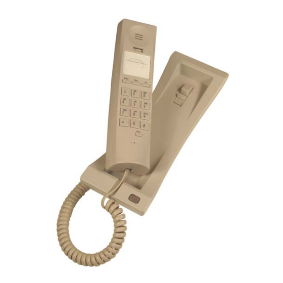
- Page 1 ® Copyright TeleMatrix Inc.2008 3300TRM 1 LINE TRIMLINE TELEPHONE SET USERS GUIDE...
-
Page 2: Introduction
INTRODUCTION Congratulations on the purchase of your TeleMatrix Trimline telephone. This telephone is a precision electronic device designed and manufactured with the highest quality components and workmanship that requires minimum maintenance. Please be sure to read the contents in this user’s guide to become familiar with its features and functionality. -
Page 3: Table Of Contents
CONTENTS Table Of Contents Introduction Features Controls Definition Of Controls Installation Parts Checklist Wall Mounting Switch Setting Care & Maintenance Service Warranty... -
Page 4: Features
FEATURES Single Line Operation Tone Dialing Message Waiting Lamp Convenient Data Port Handset Volume Control Flash Function (100mS/300mS and 600mS) ... -
Page 5: Controls
CONTROLS... -
Page 6: Definition Of Controls
DEFINITION OF CONTROLS Data Port Used for plugging in a laptop, modem, fax, etc. Redial Key Used to automatically redial the last number dial. Flash Key Provides a 100mS/300mS or 600mS time line break. Handset Volume Control Amplifies the volume of the receiver. Dial Pad Large keys used for outbound dialing. -
Page 7: Installation
INSTALLATION Caution Never install telephone wiring during a lightning storm. Never install telephone jacks in wet location unless the jack is specifically designed for wet locations. Never touch none insulated telephone wires or ... -
Page 8: Parts Checklist
15’/4.5m line cord sold seperately RJ11C/W Line Cord - 3.5/.09m Handset Coil Cord - 10’/3.05m... -
Page 9: Connecting The Line Cord
INSTALLATION Connecting The Line Cord Plug the end of the 15-foot modular telephone line cord into the jack on the top of the base unit. Plug the remaining end of the line cord into a standard telephone outlet. -
Page 10: Connecting The Handset Cord
INSTALLATION Connecting The Handset Cord Plug one end of the modular coiled handset cord into the receptacle located on the left side of the base unit. Plug the remaining end into the receptacle on the handset. -
Page 11: Wall Mounting
The TeleMatrix Trimline telephone can be wall mounted to a standard telephone wall jack plate. Using the 3.5-inch line cord, plug one end into the receptacle on the bottom of the base unit. The remaining end will plug into the wall jack. Carefully align the slots on the bottom of the base unit with the wall mount studs on the jack plate. - Page 12 INSTALLATION Handset Retaining Clip The handset retaining clip must be activated to hold the handset when wall mounting the telephone. Turn the “wall mount clip” 180 degrees. Turn...
-
Page 13: Switch Setting
SWITCH SETTING Flash Switch There is a 3-position slide switch located on the handset under the plastic cover. Use a sharp pointer to remove the switch plastic cover plate to expose the switch. The FLASH KEY can provide a 100ms/300ms and 600ms time line break. -
Page 14: Message Waiting Switch
SWITCH SETTING Message Waiting Switch There are two (2) slide switches located on the base unit under a plastic cover. Use a sharp pointer to remove the switch plastic cover plate to expose the two switches. These switches control how the message-waiting lamp (MWL) works: Position: Mode:... - Page 15 SWITCH SETTINGS Ringer Volume Control Switch There is a slide switch located on the right side of the base unit that is used to adjust the loudness of the ringing sound. A “low” and “high” setting are provided . Select the desired loudness by sliding the switch to the appropriate position.
-
Page 16: Care & Maintenance
CARE & MAINTENANCE Keep the telephone dry. If it gets wet on the outside, wipe it dry immediately. Liquids might contain minerals that can corrode the electronic circuits. Do not touch the unit if submerged in water. Call for assistance. Use and store the telephone only in normal temperature environments. -
Page 17: Service
5025 Galley Road Unit 33, Stratford Office Village Colorado Springs Walker Avenue, Milton Keynes Colorado 80915 USA Buck MK12 5TW United Kingdom TeleMatrix Middle East: PriorityCare Center, Hamriyah Free Zone, Sharjah, U.A.E. TeleMatrix will pay return postage on the repaired telephone. - Page 18 It is the re- sponsibility of users requiring service to report the need for service to our Company or to one of our authorized agents. Ser- vice can be facilitated through your regional TeleMatrix office.
- Page 19 WARRANTY...
Need help?
Do you have a question about the 3300TRM and is the answer not in the manual?
Questions and answers