Table of Contents
Advertisement
Quick Links
Advertisement
Table of Contents

Subscribe to Our Youtube Channel
Summary of Contents for YOKOGAWA EJA564E
- Page 1 User’s Manual Hygienic & Sanitary Pressure Transmitter EJA564E IM-P-20200626-01 Yokogawa Corporation of America IM-P-20200626-01 2 Dart Road, Newnan, Georgia 30265 U.S.A. ©Copyright 2020 Tel: (800) 888-6400 Fax: (770) 254-0928 1st Edition, October 2020...
-
Page 2: Table Of Contents
Hygienic & Sanitary Pressure Transmitter EJA564E IM-P-20200626-01 1st Edition CONTENTS Introduction ....................4 Description ......................4 Barometric Reference ..................4 Dimensional Drawings .................5 Installing the Transmitter ................6 Installing Weld-On Nipple ................... 6 Installing Transmitter (Code W33) ..............6 Mounting Position ....................6 Mounting Position Effect.................. - Page 3 Programming ..................... 14 Programming with Hand Held Terminal ............14 HART Commands and Parameters ..............15 Specifications .................... 16 Precautions and Warnings ............... 17 Revision Information ................... 18 IM-P-20200626-01...
-
Page 4: Introduction
(DN 25, 40 and 50), flanges (DIN and ANSI) and sanitary weld-on nipples (ø 48, 62 and 85 mm.), among others. Certain variants of the EJA564E are designed to be non-clogging and are capable of being cleaned inside. Various process connection types are manufactured according to 3-A (74-06) requirements such as Tri-Clamp and others. -
Page 5: Dimensional Drawings
<2. Dimensional Drawings> Dimensional Drawings "T20" PROCESS CONNECTION EJA564E- 1/2" NPT Electrical Connection M12 Electrical Connection Note. Standard Drawings for all other connection types are available on request. IM-P-20200626-01... -
Page 6: Installing The Transmitter
<3. Installing the Transmitter> Installing the Transmitter The diaphragm of the transmitter is protected with Position the weld-on nipple in the vessel hole a special protection cap. Protect the diaphragm and tack six places. The weld sequence is until installation takes place. Take special care shown in the figure above. -
Page 7: Connection Terminal
<3. Installing the Transmitter> 3.6 Connection Terminal The figure below shows the wiring connection of the transmitter. The 2-wires must be connected to the terminal board. The wiring terminals can be connected without a screwdriver. The opening levers of the terminal can be lifted and pressed down by hand. -
Page 8: Remaining
<4. Remaining> Remaining 4.1 External Load External loads must be placed in the negative side of the 2-wire loop. The minimum power supply is based on the total circuit resistance. The maximum external load (RI max.) for 24 Vdc will be 600 Ω (Ohm). CAUTION •... -
Page 9: Display And Push Buttons
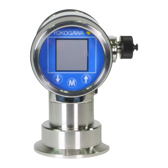
<5. Display and Push Buttons> 5. Display and Push Buttons The EJA564E has a high contrast display for optimal readout. The menu is controlled by 3 push buttons. Navigate with the up and down through menus and measuring values. Enter a menu and confirm selections with the menu button. -
Page 10: Explanation Programming Points
<6. Explanation Programming Points> Explanation of Programming Points 6.1 Zero Adjustment Example: Measurement range 0 – 2000 mbar. (ZERO) The span must be set to 2000 mbar Navigate to program point P102, and push the The transmitter is set to 0 mbar at menu button to enter the menu. -
Page 11: Display Setting Of Units
<6. Explanation Programming Points> 6.5 Output Selection Choosing Set will adjust the zero to 0.000 mbar in the mounting position when applicable. 4-20 mA or • Select Set, and push the menu button to 20-4 mA confirm. • The corrected is value is shown on the display. Factory setting = 4 - 20 mA •... -
Page 12: Temperature Units
<6. Explanation Programming Points> 6.7 Temperature 6.9 Readout Units In this menu, the type of readout on the display can be adjusted. In this menu, the preferred Factory Setting = Unit temperature unit can be selected. Navigate to program point P109, and push the Navigate to program point P107, and push the menu button to enter the menu. -
Page 13: Information
<6. Explanation Programming Points> 6.11 Information • Cmd 09 = DEVICE VARIABLES WITH STATUS • Cmd 48 = ADDITIONAL This menu summarizes information TRANSMITTER STATUS about the configuration of the transmitter. Choose the preferable burst mode, and push menu button to confirm. Below the contents of the information screen. -
Page 14: Programming
2-wire system. This is necessary for proper communication (see drawing below). A power supply of at least 17 Vdc must be used. The EJA564E can easily be programmed with the Hand Held Terminal (YHC HART Communicator). Option 1: HART Hand Held terminal connected across the transmitter. -
Page 15: Hart Commands And Parameters
<7. Explanation - Programming Points> 7.2 HART Commands and Parameters Dynamic Variables (Command #3) Note Pressure Selected units (psi...mBar) Sensor Temperature Selected units (Deg. F or C) Electronic Temperature Selected units (Deg. F or C) (Pressure) Same as PV ・Dynamic variables (PV,SV,TV,FV) and current can be read using HART Command #3. ・Device variables with Status can be read using HART Command #9. -
Page 16: Specifications
8. Specifications Please refer to the General Specifications. Document GS-P-20200626-01 for model, suffix, option codes and all required dimensional and electrical specifications. The General Specificaitions listed below can be downloaded from the Yokogawa Corporation of America website: https://www.yokogawa.com/us/solutions/products-platforms/field-instruments/ pressure-transmitters/hygienic-sanitary-transmitters/ General Specification List Document Title Document No. -
Page 17: Precautions And Warnings
• Check if the specifications of the transmitter meet the needs of the process conditions • When the EJA564E is used as a level transmitter, be aware of the place where the transmitter is mounted. Here are some suggestions: •... -
Page 18: Revision Information
For Questions and More Information If you have any questions, you can send an E-mail to the following address. support@us.yokogawa.com E-mail: n If you want have more information about Yokogawa products, you can visit Yokogawa’s homepage at the following web site. Homepage: http://www.yokogawa.com/ Marketing n Written by Dept.


Need help?
Do you have a question about the EJA564E and is the answer not in the manual?
Questions and answers