
Subscribe to Our Youtube Channel
Related Manuals for Fluke FTK200


Summary of Contents for Fluke FTK200
- Page 1 ® FTK200 Optical Fiber Test Kit Users Guide April 2000, Rev. 1 4/03 © 2000, 2003 Fluke Corporation. All rights reserved. Printed in USA. All product names are trademarks of their respective companies.
- Page 2 LIMITED WARRANTY AND LIMITATION OF LIABILITY Each Fluke product is warranted to be free from defects in material and workmanship under normal use and service. The warranty period is one year and begins on the date of shipment. Parts, product repairs, and services are warranted for 90 days. This warranty extends only to the original buyer or end-user customer of a Fluke authorized reseller, and does not apply to fuses, disposable batteries, or to any product which, in Fluke’s opinion, has been misused, altered, neglected, contaminated, or damaged by accident or abnormal conditions of operation...
-
Page 3: Table Of Contents
Table of Contents Title Page WSafety Information ..................... iv Cleaning Fiber Connections ..................iv Introduction........................1 Contacting Fluke......................2 Unpacking........................2 Features ........................4 Measuring Optical Power....................8 Setting a Reference for Loss Measurements..............10 Measuring Optical Power Loss ..................12 Memory Functions ...................... - Page 4 FTK200 Users Guide Appendix A: Using the Serial Port .................. 21 Appendix B: Glossary..................... 23...
- Page 5 List of Figures Figure Title Page Standard Equipment ......................3 FM150 Fiber Meter Features ....................4 Display Features........................6 FS150 Fiber Source Features....................7 Measuring Optical Power...................... 9 Setting a Reference ......................11 Measuring Loss........................13 Battery Replacement ......................15 List of Tables Table Title...
-
Page 6: Wsafety Information
FTK200 Users Guide Cleaning Fiber Connections W Safety Information Always clean the fiber ends before making connections. Warning Use any of the following: To avoid possible eye damage caused by • Lint-free swabs or wipes moistened with isopropyl hazardous radiation: alcohol •... -
Page 7: Introduction
Displays remaining battery life. Introduction • Designed to use the optional ToolPak™ Meter The FTK200 Optical Fiber Test Kit is used to measure Hanging Kit from Fluke. optical power and optical power loss at 850 nm, 1300 nm, • Saves up to 500 measurements for each wavelength. -
Page 8: Contacting Fluke
The equipment listed below and shown in Figure 1 is 850 nm and 1300 nm. For testing singlemode fiber, Fluke included with the FTK200 Kit. If anything is missing or offers the optional LS-1310/1550 Laser Source. damaged, contact the place of purchase immediately. -
Page 9: Standard Equipment
(with 9 V battery, (with 9 V battery, test jumper adapter cap adapter cap, and dust cap) and dust cap) ST/ST adapter Warranty registration card LinkWare PC FTK100/FTK200 utility CD-ROM Manuals CD-ROM 2 recording pads Hard carrying case afz02f.eps. Figure 1. Standard Equipment... -
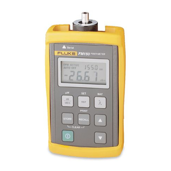
Page 10: Features
FTK200 Users Guide Features Figures 2 and 3 and Table 1 describe the meter’s features. Figure 4 describes the features of the FS150 Fiber Source included in the kit. Serial FM150 FIBER METER PRINT STORE RECALL CLEAR afz01f.eps Figure 2. FM150 Fiber Meter Features... -
Page 11: Fm150 Fiber Meter Features
Optical Fiber Test Kit Features Table 1. FM150 Fiber Meter Features Item Description On/off key. Hold down to turn the meter on. The automatic power-down feature, which turns the meter off if no keys are pressed for 5 minutes, is enabled when you turn the meter on. To disable this feature, turn the meter off; then hold down until P is displayed. -
Page 12: Display Features
FTK200 Users Guide Measurement display. is displayed if the optical power reading is too small to display. is displayed if the reading is too large to display. For output power measurements, the unit is µW or . For loss measurements, the unit is... -
Page 13: Fs150 Fiber Source Features
Optical Fiber Test Kit Features On/off switch. The switch lights up when the source is on and blinks when the battery is low. 1300 Slide switch for selecting 850 nm or 1300 nm light output. ST connector for 850 nm or 1300 nm light output. FS150 FIBER SOURCE afz03f.eps... -
Page 14: Measuring Optical Power
FTK200 Users Guide Clean all fiber ends. Measuring Optical Power Make the connections shown in Figure 5. Optical power is the output power produced by a source such as an optical network interface card or optical test Verify that the meter is in the power measurement equipment. -
Page 15: Measuring Optical Power
Optical Fiber Test Kit Measuring Optical Power Optical patch cord Optical Optical patch cord Fiber link patch cord OUTPUT Optical network interface Optical card or optical source connections Serial FM150 FIBER METER Serial OUTPUT FM150 FIBER METER FM150 Fiber Meter FM150 Optical network interface Fiber Meter... -
Page 16: Setting A Reference For Loss Measurements
FTK200 Users Guide To view the reference for the selected wavelength, press Setting a Reference for Loss briefly. Measurements To set a reference, proceed as follows: Setting a reference lets the meter automatically subtract from loss measurements the losses due to patch cords. - Page 17 Optical Fiber Test Kit Setting a Reference for Loss Measurements Known-good adapter Known-good patch cords of the same type as the fiber to be tested and ST at the meter end Serial FM150 FIBER METER 1300 FS150 FIBER SOURCE PRINT STORE RECALL CLEAR...
-
Page 18: Measuring Optical Power Loss
FTK200 Users Guide Clean all fiber ends. Measuring Optical Power Loss Set a reference, if necessary. (See the previous Optical power loss is the light energy lost through the fiber, section “Setting a Reference for Loss Measurements” adapters, splices, and other components in a fiber link. -
Page 19: Measuring Loss
Optical Fiber Test Kit Measuring Optical Power Loss Optical test jumper Fiber Link Optical connectons Patch cords and adapter used to set the reference Serial FM150 FIBER METER 1300 PRINT FS150 FIBER SOURCE STORE RECALL CLEAR FS150 Fiber Source FM150 Fiber Meter afz06f.eps Figure 7. -
Page 20: Memory Functions
FTK200 Users Guide To exit the recall mode, press Memory Functions Replacing Saved Measurements The FM150 Fiber Meter lets you save loss and power measurements in non-volatile memory. Saved You can save a new measurement in any memory measurements are not lost when you change the battery. -
Page 21: Maintenance
Optical Fiber Test Kit Maintenance Maintenance Clean the case with a soft cloth dampened with water or a mild detergent. Do not use solvents or abrasive cleansers. Always cover the connector with the dust cap when not using the meter. Do not open the case (except to replace the battery). -
Page 22: Accessories And Replacement Parts
Users Guide Accessories and Replacement Parts Table 2. Accessories and Replacement Parts (cont.) Table 2 shows the accessories and replacement parts Fluke Model or available from Fluke for the FTK200 Optical Fiber Test Kit. Description Part Number LS-1310/1550 Laser Source LS-1310/1550 Table 2. -
Page 23: Calibration And Service
Calibration and Service For service, contact an authorized service center. To locate the nearest service center, contact Fluke as Have the meter calibrated at an authorized Fluke Service described at the beginning of this guide. Center every 12 months. FM150 Fiber Meter Specifications... -
Page 24: Fs150 Fiber Source Specifications
FTK200 Users Guide FM150 Fiber Meter Specifications (cont.) Memory Stores up to 500 measurements for each wavelength. Measurements are stored in non-volatile memory, which is retained when power is off or the battery is changed. Memory contents can be uploaded to a PC or sent directly to a serial printer. - Page 25 Optical Fiber Test Kit FS150 Fiber Source Specifications FS150 Fiber Source Specifications (cont.) ±0.1 dB per 8 hours at 25 °C Stability Battery type and life 9 V alkaline (NEDA 1604A or IEC 6LR61); 30 hours typical with alkaline battery Low battery indication Blinking LED in power switch Temperature range...
- Page 26 FTK200 Users Guide...
- Page 27 Appendix A Serial Communications Using the Serial Port Table 3. Pin Assignments for Serial Cable The serial port on the FM150 Fiber Meter lets you send Phone Plug Pins on 9-pin saved measurements to a PC or a serial printer. Conductor Connector Signal...
- Page 28 FTK200 Users Guide Sending Measurements to a Printer Sending Measurements to a PC To send measurements directly to a serial printer, proceed To send measurements to a PC, use the LinkWare™ as follows: software provided with the meter. Turn on the FM150 Fiber Meter and the printer.
- Page 29 Appendix B Glossary Adapter A device used to mate fiber connectors of the same or A unit of power (in decibels), assuming a reference of different styles. 1 mW (1/1000 of a watt). Attenuation Insertion loss A loss of optical power due to losses in the fiber itself or in Loss of optical power caused by adding a connector, connections between fibers.
- Page 30 FTK200 Users Guide Macrobending losses SC connector Light losses due to large-radius bends in a fiber, such as Subscription Channel Connector. An optical connector that bends made during installation. originated in Japan and provides push-pull connections, low loss, and low backreflection.
Need help?
Do you have a question about the FTK200 and is the answer not in the manual?
Questions and answers