
Related Manuals for RuggedCom RX1512


Summary of Contents for RuggedCom RX1512
- Page 1 FCC Statement And Cautions Product Overview RUGGEDCOM Modules RUGGEDCOM RX1512 Installation Technical Specifications EMI And Environmental Type Tests Installation Guide Agency Approvals Warranty 6/2013...
-
Page 2: Security Information
This document contains proprietary information, which is protected by copyright. All rights are reserved. No part of this document may be photocopied, reproduced or translated to another language without the prior written consent of RuggedCom Inc. Disclaimer Of Liability Siemens has verified the contents of this manual against the hardware and/or software described. -
Page 3: Table Of Contents
3.1 Mounting ............................ 13 3.1.1 RX1512Dimensions ......................15 3.2 Power Supply Wiring and Grounding ................... 17 3.2.1 RX1512 DC Power Connectors ..................17 3.2.2 Chassis Ground Connection ..................... 17 3.2.3 DC Power Supply Wiring Example ................... 18 3.3 Critical Alarm Wiring ........................18 3.4 Serial Console Port ........................ - Page 4 RUGGEDCOM RX1512 Table of Contents Installation Guide 3.7 Copper Ethernet Ports ........................ 20 3.7.1 RJ45 Twisted-Pair Copper Ports ..................20 3.7.2 M12 Twisted Pair Copper Ports ..................21 3.7.3 Gigabit Ethernet 1000Base-TX Cabling Recommendations ..........21 3.7.4 Transient Suppression ..................... 22 3.8 Serial Ports: RJ45 ........................
-
Page 5: Fcc Statement And Cautions
This product contains no user-serviceable parts. Attempted service by unauthorized personnel shall render all warranties null and void. Changes or modifications not expressly approved by RuggedCom Inc. could invalidate specifications, test results, and agency approvals, and void the user’s authority to operate the equipment. - Page 6 RUGGEDCOM RX1512 Installation Guide FCC Statement And Cautions...
-
Page 7: Product Overview
Section 1.1 Functional Overview The RUGGEDCOM RX1512 is a cost-efficient, rugged layer 3 switch and router. The RX1512’s modular and field replaceable platform allows you to select WAN, serial, and Ethernet options, making it ideally suited for electric power utilities, the industrial plant floor, and traffic control systems. The appliance’s compact form factor makes it ideal for pole mount applications or installation in restricted spaces. - Page 8 Chapter 1 RUGGEDCOM RX1512 Product Overview Installation Guide • Up to 12 ports 100FX • Up to 12 ports 10/100TX • Up to 4 ports Gigabit Ethernet WAN Port Options • Up to 4 T1/E1 ports via RJ45 connectors (channelized/unchannelized) •...
-
Page 9: Installation
RUGGEDCOM RX1512 Chapter 1 Installation Guide Product Overview Warranty • 5 Year Warranty Feature Highlights... - Page 10 RUGGEDCOM RX1512 Chapter 1 Installation Guide Product Overview Feature Highlights...
-
Page 11: Ruggedcom Modules
Installing a Module To install a module into the RUGGEDCOM chassis, align the module guide ribs with the channels on the chassis. Push the module in as far as it will go, being sure to push through the resistance provided by the grounding springs. -
Page 12: Front Panel
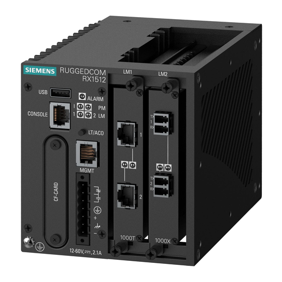
Section 2.2 Front Panel The RX1512 Front Panel is equipped with an RS232 serial console port for initial management functions, and a locally connected 10/100Base-T Ethernet port for system management out of band from the switch fabric. Figure 2: Front View Other Front Panel features include: •... -
Page 13: Module Status Leds
Section 2.3 Line Modules (LM) The RUGGEDCOM RX1512 supports two line modules in slots LM1 through LM2. Several types of line modules may be ordered, depending on the type, speed and number of Ethernet ports required. The following illustrations show the typical port configurations and connectors available for RX1512 line modules. -
Page 14: Ethernet - Fiber
Chapter 2 RUGGEDCOM RX1512 RUGGEDCOM Modules Installation Guide Figure 6: 4TX03: 4 x 8-Pin 10/100TX M12 Figure 5: 6TX01: 6 × 10/100TX RJ45 Figure 7: 4TX04: 4 x 4-Pin 10/100TX M12 Section 2.3.2 Ethernet - Fiber Figure 8: FX**/FG**: 2 × 100FX/1000SX/1000LX LC Figure 9: 4FX**: 4 ×... -
Page 15: Sfp Modular
RUGGEDCOM RX1512 Chapter 2 Installation Guide RUGGEDCOM Modules Section 2.3.3 SFP Modular Figure 15: FG5*: 2 × 1000LX/1000SX SFP Figure 16: FX5*: 4 × 100FX/100LX/100SX SFP Figure 17: 6FX50: 6 × 100FX SFP Section 2.3.4 Figure 18: TC1: 1 × T1/E1 RJ45 Figure 19: E01: 1 ×... -
Page 16: Technical Specifications
Chapter 2 RUGGEDCOM RX1512 RUGGEDCOM Modules Installation Guide The TC1, TC2 and TC4 WAN modules meet the Industry Canada's CS-03 Part II, Issue 9 technical specifications. The industry Canada registration number and model number is provided on a label on top of the modules. -
Page 17: Ruggedape™ (Appplication Processing Engine)
Section 2.4 Power Supply The RX1512 power supply is integrated with the Control Module. The power supply and fail-safe relay connections are made on a pluggable terminal block located on the front panel of the Control Module. The RX1512 power supply input is 11VDC to 72VDC, and consumes a maximum of 25W. - Page 18 RUGGEDCOM RX1512 Chapter 2 Installation Guide RUGGEDCOM Modules Power Supply...
-
Page 19: Installation
Section 3.1 Mounting The RUGGEDCOM RX1512 features optional mounting brackets for panel and DIN rail mounting. The optional brackets attach to both sides of the appliance at the rear of the chassis. For panel mounting, the mounting bracket provides four mounting holes. For DIN rail mounting, the DIN adaptor mounts to a standard 1" DIN rail and is secured with a lock screw on each adaptor. - Page 20 Chapter 3 RUGGEDCOM RX1512 Installation Installation Guide Figure 30: DIN Rail Mounting: Front View Figure 31: DIN Rail Mounting: Side View Mounting...
-
Page 21: Rx1512Dimensions
RUGGEDCOM RX1512 Chapter 3 Installation Guide Installation Section 3.1.1 RX1512Dimensions Figure 32: RX1512 Dimensions – Front View RX1512Dimensions... - Page 22 Chapter 3 RUGGEDCOM RX1512 Installation Installation Guide Figure 33: RX1512Dimensions – Top View Figure 34: RX1512 Dimensions – Side View RX1512Dimensions...
-
Page 23: Power Supply Wiring And Grounding
Installation Section 3.2 Power Supply Wiring and Grounding The RX1512 features a Phoenix Plug Terminal Block. Both DC power supply and fail-safe relay connections are made on the same terminal block. For DC power supply wiring examples, refer to Section 3.2.3, “DC Power Supply Wiring Example”. -
Page 24: Dc Power Supply Wiring Example
Section 3.3 Critical Alarm Wiring The Critical Alarm output relay signals critical error conditions that may occur on the RUGGEDCOM RX1512. The contacts are energized upon power-up of the unit and remain energized unless a critical alarm condition is detected. Relay connections are shown in the Critical Alarm Relay Connector diagram. -
Page 25: Serial Console Port
Figure 39: RJ45 Serial Console Port NOTE The RX1512 connects the DSR/RI, RLSD, and DTR pins internally and does not drive or require these pins. The RX1512 connects the CTS and RTS pins internally and does not drive or require these pins. -
Page 26: Wan Ports: Bnc
T1/E1 pinout Description Section 3.6 WAN Ports: BNC The RX1512 supports optional E1 WAN ports with BNC connectors. The Tx and Rx connections are labelled on the line module. See the illustration below for the connection configuration. RTIP TTIP Chassis... -
Page 27: M12 Twisted Pair Copper Ports
RUGGEDCOM RX1512 Chapter 3 Installation Guide Installation RJ45 Pin 10/100Base-Tx 10/100/1000Base-Tx Section 3.7.2 M12 Twisted Pair Copper Ports M12 ports are available on LMs that support 10/100Base-TX and 10/100/1000Base-TX. See the illustrations and tables below for pin configuration and assignmnt. -
Page 28: Transient Suppression
Section 3.8 Serial Ports: RJ45 The RX1512 supports serial port line modules with RJ45 connections. On power-up, all serial ports default to RS485 mode. Each port can be individually set to RS232, RS485, or RS422 mode via software. Transient Suppression... -
Page 29: Dds Ports: Rj45
Section 3.9 DDS Ports: RJ45 The RX1512 supports DDS port line modules with RJ45 connections. The 56 kbps DDS port is compatible with Bellcore standards. Each DDS module features a single 56/64 kbps DDS line interface with a standard RJ45 receptacle. -
Page 30: Sfp Optics - Installation, Removal, And Precautions
SFP Optics – Installation, removal, and precautions The RX1512 can be ordered with SFP (Small Form-factor Pluggable) pluggable optics modules. SFP modules can be safely inserted and removed while the chassis is powered and operating. When inserting or removing optics, observe the following precautions: •... -
Page 31: Module Insertion - Sfp
Module Insertion – SFP Special attention must be paid to the orientation of SFP modules upon installation in the RX1512 chassis. The figure below shows the proper orientation of SFP modules installed in both upper and lower line modules. SFP modules on the upper row must be inserted top-side up. -
Page 32: Sfp Module Removal
Chapter 3 RUGGEDCOM RX1512 Installation Installation Guide Figure 49: SFP module insertion SFP modules should slide gently into their ports and should lock in place when fully inserted. Dust covers should be in place when installing the modules, and should always be in place when cables are not connected. -
Page 33: Fiber Ethernet Ports
Section 3.12 Fiber Ethernet Ports Depending on the order code of the product, the RUGGEDCOM RX1512 can be equipped with several different types of fiber optic ports. The Transmit (TX) and Receive (RX) connections of each port must be properly connected and matched for proper link establishment and operation. -
Page 34: Cellular Modems
Section 3.13 Cellular Modems The RX1512 can be equipped with cellular modem modules for operation on GSM, EDGE, HSPA+, or CDMA networks. The cellular modems feature 50 Ω SMA antenna connectors on the front plate of each module. The following cellular modem modules are available:... -
Page 35: Gsm, Edge, Hspa+ Cellular Modem Card
RUGGEDCOM RX1512 Chapter 3 Installation Guide Installation Figure 56: Dual Port Cellular Modem: Antenna Connections NOTE If two or more antennas are to be installed, the antennas must be separated by a minimum distance of 20 cm (7.9"). Section 3.13.1 GSM, EDGE, HSPA+ Cellular Modem Card The HSPA option is available for use on various GSM based networks. -
Page 36: Installing Sim Cards For Gsm, Edge, Hspa+ Cellular Modems
NOTE Be sure to take appropriate anti-static precautions before opening the cellular modem module. 1. Remove the module from the RX1512. 2. On the smooth side of the module, remove the four screws and remove the back of the module. -
Page 37: Technical Specifications
Voltage Current 30VDC Section 4.3 Copper Ethernet Port Specifications The RX1512 can be ordered with several different modules which contain 10/100Tx or 10/100/1000Tx Ethernet ports. All copper Ethernet ports have the following specifications: Table: Copper Ethernet Port Specifications Parameter Specification... -
Page 38: Fiber Ethernet Port Specifications
RX1512. The specifications are organized by order code. Module order codes are contained within each unit when it is assembled and configured at the factory. Consult the RuggedCom RX1512 User Guide for help in obtaining the factory configuration data. -
Page 39: Gigabit Ethernet (1Gbps) Optical Specifications
1. Maximum segment length is greatly dependent on factors such as fiber quality, and the number of patches and splices. Please consult RuggedCom sales associates when determining maximum segment distances. 2. All optical power numbers are listed as dBm averages. -
Page 40: Operating Environment
Chapter 4 RUGGEDCOM RX1512 Technical Specifications Installation Guide 3. F51 transceivers are rated for -40°C to +85°C. Section 4.5 Operating Environment Table: Operating Environment Parameter Range Comments Ambient Operating Temperature -40°C to 85°C Ambient Temperature as measured from a 30cm radius surrounding the center of the enclosure. - Page 41 RUGGEDCOM RX1512 Chapter 4 Installation Guide Technical Specifications Parameter Value Comments Ingress Protection IP40 Enclosure Aluminum Mechanical Specifications...
- Page 42 RUGGEDCOM RX1512 Chapter 4 Installation Guide Technical Specifications Mechanical Specifications...
-
Page 43: Emi And Environmental Type Tests
RUGGEDCOM RX1512 Chapter 5 Installation Guide EMI And Environmental Type Tests EMI And Environmental Type Tests Table: IEC 61850-3 EMI Type Tests Severity Test Description Test Levels Levels IEC 61000-4-2 Enclosure Contact +/- 8 kV Enclosure Air +/- 15 kV... - Page 44 Chapter 5 RUGGEDCOM RX1512 EMI And Environmental Type Tests Installation Guide Table: IEEE 1613 (C37.90.x) EMI Immunity Type Tests Test Description Test Levels IEEE C37.90.3 Enclosure Contact +/-2kV, +/-4kV, +/- 8kV Enclosure Air +/-4kV, +/-8kV, +/-15kV IEEE C37.90.2 Radiated RFI...
-
Page 45: Agency Approvals
RUGGEDCOM RX1512 Chapter 6 Installation Guide Agency Approvals Agency Approvals Table: Agency Approvals Agency Standards Comments UL 60950-1:2007, CAN/CSA-C22.2 No. 60950-1-07 CE Compliance is claimed via EN 60950, EN 61000-6-2 Declaration of Self Conformity Route FCC Part 15, Class A... - Page 46 RUGGEDCOM RX1512 Chapter 6 Installation Guide Agency Approvals...
-
Page 47: Warranty
Warranty Warranty RuggedCom warrants this product for a period of five (5) years from the date of purchase. This product contains no user-serviceable parts. Attempted service by unauthorized personnel shall render all warranties null and void. For warranty details, visit www.RuggedCom.com... - Page 48 RUGGEDCOM RX1512 Chapter 7 Installation Guide Warranty...
Need help?
Do you have a question about the RX1512 and is the answer not in the manual?
Questions and answers