Jet J-8201 Operating Instructions And Parts Manual
14-inch vertical band saws
Hide thumbs
Also See for J-8201:
- Operating instructions and parts manual (37 pages) ,
- Operating instructions and parts manual (36 pages) ,
- Operating instructions and parts manual (36 pages)
Table of Contents
Advertisement
Operating Instructions and Parts Manual
14-Inch Vertical Band Saws
Models: J-8201, J-8203, J-8201VS, J-8203VS
WALTER MEIER (Manufacturing), Inc.
427 New Sanford Road
LaVergne, Tennessee 37086
Ph.: 800-274-6848
www.waltermeier.com
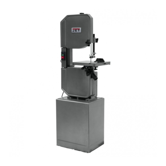
Model J-8201 shown
Copyright © 2012 Walter Meier (Manufacturing), Inc.
This .pdf document is bookmarked
This Manual is Bookmarked
Part No. M-414500
Revision B1 01/2012
Advertisement
Table of Contents

Related Manuals for Jet J-8201


Summary of Contents for Jet J-8201
-
Page 1: Cover Page
This .pdf document is bookmarked This Manual is Bookmarked Operating Instructions and Parts Manual 14-Inch Vertical Band Saws Models: J-8201, J-8203, J-8201VS, J-8203VS Model J-8201 shown WALTER MEIER (Manufacturing), Inc. 427 New Sanford Road LaVergne, Tennessee 37086 Part No. M-414500 Ph.: 800-274-6848... - Page 2 Authorized Service Centers located throughout the United States can give you quick service. In most cases, any of these Walter Meier Authorized Service Centers can authorize warranty repair, assist you in obtaining parts, or perform routine maintenance and major repair on your JET® tools. For the name of an Authorized Service Center in your area call 1-800- 274-6848.
-
Page 3: Table Of Contents
Table of Contents Cover Page ....................1 General Specifications ................4 Warnings and Safety ................... 5 Set-up and Operation .................. 8 Operating Instructions ................13 Maintenance ....................17 Troubleshooting ..................19 Replacement Parts ................... 22 Wiring Diagram... -
Page 4: General Specifications
General Specifications JET’s 14-inch Vertical Band Saws are specially de- signed to effectively cut a variety of materials includ- ing wood, plastic, bakelite, composites, ferrous and non-ferrous metals. Models J-8201 and J-8203 are wood and metal cutting band saws. JET’s Model J-8201VS and J-8203VS 14-inch Vari-... -
Page 5: Warnings And Safety
cal supply while servicing. - Misuse of this machine can cause serious injury. - Always follow instructions in Operating Instruc- - For safety, machine must be set up, used and tions and Parts Manual when changing acces- serviced properly. sory tools or parts. - Read, understand and follow instructions in the - Never modify the machine without consulting Operating Instructions and Parts Manual which... -
Page 6: General Electrical Cautions
be carefully checked to determine that it will operate General Electrical Cautions properly and perform its intended function - check for This saw should be grounded in accordance with alignment of moving parts, binding of moving parts, the National Electrical Code and local codes and or- breakage of parts, mounting, and any other condi- dinances. -
Page 7: Safety Instructions On Sawing Systems
Safety Instructions on Sawing Systems 1. Always wear leather gloves when handling saw as possible to the workpiece. blade. The operator shall not wear gloves when 9. Always wear protective eye wear when operat- operating the machine. ing, servicing, or adjusting machinery. Eyewear 2. -
Page 8: Setup And Operation
This manual includes operating and maintenance in- Set-up structions for the JET14-Inch Vertical Band Saws, Models J-8201, J-8203, J-8201VS, and J-8203VS. This The band saw is shipped with the saw frame manual also includes parts listings and illustrations separated from the saw base. Set-up of the band of replaceable parts. - Page 9 CODES WHEN ATTACHING THIS BAND SAW TO YOUR POWER SUPPLY. Electrical Switch 1-ph. Models J-8201 and J-8201VS are delivered with a 115 Motor power Plug volt single phase motor. Models J-8203 and J-8203VS source are delivered with a 220/440 volt, 3-phase motor.
- Page 10 2. Grounded, cord-connected tools intended for GROUNDING INSTRUCTIONS use on a supply circuit having a nominal rating less than 150 volts: 1. All grounded, cord-connected tools: This tool is intended for use on a circuit that has an In the event of a malfunction or breakdown, grounding outlet that looks like the one illustrated in Sketch A.
- Page 11 For 115/230V For 115 only...
- Page 12 Installing Optional Frame Riser are checked and adjusted as required. 18. Install the extension plug cable between the NOTE: Refer to the illustrations in the Replacement motor plug and switch plug. Parts section for location of the parts used on 19.
-
Page 13: Operating Instructions
Operating Instructions Figure 6 provides suggested blade speeds for various types of materials. The recommended speeds should be decreased 30 to 50% when using carbon steel blades. (The chart provides speeds Operating Controls that are based on cutting a 4-inch thick work piece using a bi-metal blade without cutting fluid.) START/STOP Switch The following conditions should also be consid-... -
Page 14: Adjusting Blade Tension
Adjustments Adjusting Blade Support/Guide Height The upper blade support and guide mechanism can be adjusted to accomodate the height of the work piece. 1. To adjust the support, loosen the knob that clamps the support rod, then move the support up or down in its holder. - Page 15 Loosen the table lock knobs and hold the Adjusting Blade Speed table firmly against its positive leveling stop. (Models J-8201/J-8203) 6. Using a machinist’s square, check to make sure the table is 90 degrees to the blade. Figure 6 on page 9 provides blade speeds for USING LEATHER PROTECTIVE GLOVES, various materials.
- Page 16 1. Turn the main switch to off. 5. Release the weight of motor so the motor pivots downward. The weight of the motor is 2. Pull the door open on the pulley case. provide adequate belt tension. 3. Turn the clutch handle clockwise and push in, to engage the high speed pulley drive.
-
Page 17: Maintenance
Maintenance 10. Install the belts as required (refer to Figure 10). 11. Release the weight of motor so the motor pivots downward. The weight of the motor will provide adequate belt tension. This section contains periodic maintenance 12. The weight of the motor should provide recommendations and maintenance procedures. - Page 18 9. USING LEATHER GLOVES AND ANSI Z87.1 Leveling Table leveling EYEWEAR TO PROTECT YOURSELF FROM bolt lock bolt Trunnion Blade THE CUTTING BLADE, carefully remove the attachment support blade from the drive wheels. Remove the bolts bearing blade out of the saw table through the table. 10.
-
Page 19: Troubleshooting
Draining and refilling the reduction gearbox. Blade WARNING: The saw must be turned off and Blade support bearing power disconnected any time the gearbox lubricant is being drained or filled. Guide block Support 1. Unplug the electrical cord or open the circuit set screws bearing breaker in the branch circuit. -
Page 20: Periodic Maintenance
Periodic Maintenance Maintenance Item Action Interval Replace blade when teeth are Saw blade Listen for sound of Whenever broken missing teeth operating saw Replace blade when bent — or worn Observe cutting Whenever — Use a wider blade for more action for cleanness operating saw accurate straight cuts... - Page 21 Troubleshooting Probable cause Suggested remedy Fault 1. Material loose in vise. 1. Clamp work securely. Excessive blade 2. Incorrect speed or feed. 2. Refer to Figure 6 or check breakage Machinist’s Handbook for speed/ feed appropriate for the material being cut. 3.
-
Page 22: Replacement Parts
Replacement Parts This section provides exploded view illustrations that show the replacement parts for the JET Model J-8201, J-8203, J-8201VS, and J-8203VS Vertical Band Saws. Also provided are parts listings that provide part number and description. The numbers shown on the illustration relate to the item number in the corresponding parts listing. - Page 23 Exploded View and Parts Listing– Base– Models J-8201 and J-8203 In No. Part No. Description Size Qty. 1 ..J-5513834 ..... Closed Stand ..................1 ... J-5507565 ..... Closed Stand Assembly w/o Motor ............1 2 ..J-5513835 ..... Door ...................... 1 3 ..
- Page 24 Exploded View and Parts List – Base –Models J-8201VS and J-8203VS In No. Part No. Description Size Qty. 1 ..J-5513860 ..... Closed Stand ..................1 2 ..J-5513835 ..... Door ...................... 1 3 ..5513836 ......Lock ...................... 1 4 ..
- Page 25 Exploded View – Saw Head – Models J-8201K, J-8203K, J-8201VS, and J-8203VS...
- Page 26 Parts List – Saw Head – Models J-8201K, J-8203K, J-8201VS, and J-8203VS In No. Part No. Description Size Qty. 1 ..J-5782511 ..... Upper Arm, Frame ................. 1 2 ..J-5783041 ..... Base ...................... 1 3 ..5783241 ......Dowel Pin ....................4 4 ..
- Page 27 Parts List – Saw Head – Models J-8201K, J-8203K, J-8201VS, and J-8203VS In No. Part No. Description Size Qty. 58 ..5782881 ......Flange Nut ............M5 ......12 59 ..5783581 ......Hex Nut ............... M8 ......5 60 ..5625361 ......Hex Nut ............... M12 ......1 61 ..
- Page 28 Parts List – Saw Head – Models J-8201K, J-8203K, J-8201VS, and J-8203VS In No. Part No. Description Size Qty. 117 ..5783721 ......Handle ....................2 118 ..5783681 ......Setting Bushing ..................2 119 ..5783771 ......Spacer ....................2 121 ..
- Page 29 Exploded View – Gearbox – Models J-8201 and J-8203...
- Page 30 Parts List – Gearbox – Models J-8201 and J-8203 In No. Part No. Description Size Qty.... J8201-GB ...... Gearbox Complete (includes all items below, except #26 and 27) ... 1 ..J-5783831 ..... Housing Gearbox ................... 1 2 ..5513791 ......Packing ....................1 3 ..
- Page 31 Exploded View – Gearbox – Models J-8201VS and J-8203VS...
- Page 32 Parts List – Gearbox – Models J-8201VS and J-8203VS In No. Part No. Description Size Qty. 1 ..J-5313790 ..... Housing Gearbox ................... 1 2 ..5513791 ......Packing ....................1 3 ..5783861 ......Plug ....................... 2 4 ..5783911 ......Oil Level Glass ..................1 5 ..
- Page 33 Parts Listing– Optional Riser Block– All Models In No. Part No. Description Size Qty. 1 ..J-5784511 ..... Riser Block ................... 1 2 ..5784521 ......Blade Guard ..................1 3 ..5784551 ......Hex Head Screw ..........5/8x8-1/2 ....1 4 ..
- Page 34 5782171 Rip Fence Assembly (Optional Equipment) In No. Part No. Description Size Qty. 2 ..JWBS18-431 ....Knob ....................1 3 ..JWBS18-432 ....Lock Handle..................1 4 ..JWBS18-433 ....Lock Plate ..................1 5 ..JWBS18-434 ....Pad ....................5 6 ..
-
Page 35: Wiring Diagram
Wiring Diagram Single Phase CAPACITOR CAPACITOR 115V 20 µ fd 250VAC 230V 20 µ fd 250VAC 300MFD 125VAC 300MFD 125VAC START START WHITE WHITE WHITE WHITE BLACK BLACK BLACK BLACK STOP STOP GREEN GREEN GREEN GREEN GROUND GROUND Three Phase 230V 460V START... - Page 36 WALTER MEIER (Manufacturing), Inc. 427 New Sanford Road LaVergne, Tennessee 37086 Ph: 800-274-6848 www.waltermeier.com...
Need help?
Do you have a question about the J-8201 and is the answer not in the manual?
Questions and answers