Table of Contents
Advertisement
Quick Links
Advertisement
Table of Contents

Subscribe to Our Youtube Channel
Related Manuals for Jet JWBS-18SFX


Summary of Contents for Jet JWBS-18SFX
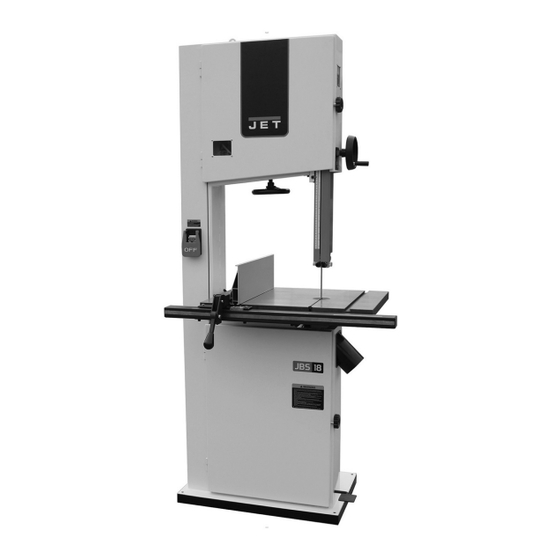
- Page 1 Operating Instructions and Parts Manual 18-inch Woodworking Band Saw Model JWBS-18SFX, JWBS-18SFX-3 427 New Sanford Road LaVergne, Tennessee 37086 Part No. M-JT1-548 / M-JT1-549 Ph.: 800-274-6848 Edition 1 02/2024 www.jettools.com Copyright © 2024 JET...
-
Page 2: Important Safety Instructions
22. Do not remove jammed, cut-off pieces until blade has stopped. 5. Do not use this band saw for other than its intended use. If used for other purposes, JET 23. Remove adjusting keys and wrenches. Form a disclaims any real or implied warranty and holds... - Page 3 Do not overreach or use excessive force to 37. Remove loose items and unnecessary work perform any machine operation. pieces from area before starting machine. 31. Use the right tool at the correct speed and feed 38. Keep hands out of path of saw blade. Do not rate.
-
Page 4: Table Of Contents
10.0 User Maintenance ............................23 10.1 Lubrication Points ........................... 23 10.2 Additional Servicing ..........................24 11.0 Blade Selection Guide ..........................24 12.0 Troubleshooting JWBS-18SFX Band Saw ....................25 12.1 Operational Problems ..........................25 12.2 Mechanical and Electrical Problems ...................... 26... -
Page 5: About This Manual
Additional knowledge can be obtained from experienced users or trade articles. Whatever accepted methods are used, always make personal safety a priority. If there are questions or comments, please contact your local supplier or JET. JET can also be reached at our website: www.jettools.com. -
Page 6: Specifications
4.0 Specifications Table 1 Model number JWBS-18SFX JWBS-18SFX-3 Stock numbers Band Saw with Stand JT1-549 JT1-548 Motor and electrical Motor type Totally enclosed fan-cooled induction, capacitor run Horsepower 1.75 HP (1.3 kW Copper Wire) 3 HP (2.2kW Copper Wire) Motor phase... - Page 7 L = length, W = width, H = height The specifications in this manual were current at time of publication, but because of our policy of continuous improvement, JET reserves the right to change specifications at any time and without prior notice, without incurring obligations.
-
Page 8: Setup And Assembly
5.2 Tools Required for Assembly Read and understand the (Note: Additional tools may be needed for entire contents of this manual before attempting adjustments.) assembly or operation. Failure to comply may cause serious injury. 2.5mm ball hex wrench (provided) 3mm, 4mm, 5mm, 6mm hex wrenches (provided) 5.0 Setup and Assembly 10mm,14mm wrenches Rubber mallet (or hammer and block of wood) -
Page 9: Installing Upper Dust Chute
Note: A blade is not provided with the saw. You may Figure 5-4). Only hand tighten screws at this time – purchase one locally or from your JET dealer. See blade must be installed and table aligned before sect. 4.0 for blade requirements of the JWBS- fully tightening. -
Page 10: Replacing Wood Insert
3. Open upper and lower doors by rotating Size of Wood Insert: doorknobs. 70 L x 113 W x 7.5 Th mm (2-3/4 L x 4-3/16 W x 1/4 Th in.) 4. Swing the lower blade guard (M – Figure 5-14) to the left. -
Page 11: Blade Tension
5.9 Blade Tension 5.10 Blade Tracking Refer to Figures 5-9 and 5-10. Refer to Figures 5-9, 5-10, and 5-11. Blade tension should be checked following blade After proper tensioning, the blade must be tracked. replacement, and periodically as the blade stretches “Tracking”... -
Page 12: Blade Guides Overview
5.11 Blade Guides Overview Thrust (back support) bearings are located behind saw blade and provide support to back of blade when saw is in operation. Guide bearings are located on either side of saw blade and provide stability for blade when saw is in operation. -
Page 13: Lower Blade Guides
5.14 Lower Blade Guides back of blade. See Figure 5-15. Do not deflect blade by pushing into it. Blade teeth are sharp; use care when working near saw blade. Refer to Figure 5-14. 1. Disconnect band saw from power source. 2. -
Page 14: Installing Guide Rail And Fence
5. Slide the resaw fence onto the fence lock bar as shown in Figure 5-23. Tighten the lock bar handles. If fence is difficult to slide onto fence lock bar, try lifting the fence lock handle or loosening the lock bar handles more. Figure 5-17: Squaring Table to Blade 5.16 Installing Guide Rail and Fence 1. - Page 15 5.16.2 Fence to Blade Alignment 1. Set table at 90° to blade and lock in position. 2. Move fence against blade (do not deflect blade by pushing into it). See Figure 5-26. 3. Verify that fence, top-to-bottom, lies flat against side of blade.
-
Page 16: Setting Up Brake Pedal
3-pole receptacles that accept the tool's plug. Repair or replace damaged or worn cord immediately. For Model JWBS-18SFX – 115V This model is intended for use on a 115V circuit and has a grounded outlet that matches the band saw electrical cord plug, as shown in Figure 6-1. -
Page 17: Extension Cords
Zero setting of cursor cannot be used with horizontal fence position. Figure 6-1: 115V Connection For Model JWBS-18SFX-3 – 230V This model is intended for use on a 230V circuit and has a grounded outlet that matches the band saw electrical cord plug, as shown in Figure 6-2. -
Page 18: Guide Post
7.4 Guide Post 2. If miter gauge is not square to blade, loosen handle (A ) and adjust until square. Tighten Refer to Figures 7-4 and 7-5. handle. 1. Loosen lock knob (see G , Figure 7-4) and raise 3. Verify that pointer (A ) shows 90°. -
Page 19: Drive Belt Adjustments
7.5 Drive Belt Adjustments 7.6 Wheel Brush The drive belt and pulleys are properly adjusted by An adjustable brush is located in lower wheel the manufacturer. However, belt tension should be housing (see Figure 7-7). It should remain in occasionally checked when the band saw is new, as constant contact with wheel to prevent buildup of a new belt may stretch slightly during the breaking- gum and debris. -
Page 20: Operating Controls
and hold the brake pedal, shown in Figure 8-3. The 8.0 Operating Controls blade will stop moving in a few seconds after pedal is pressed. Restart saw by pressing start switch on 8.1 Start/Stop Switch column. In case of emergency, always use the brake pedal Refere to Figure 8-1. -
Page 21: Ripping
When cutting, do not overfeed Using the fence in conjunction the blade; overfeeding will reduce blade life and with the miter gauge can cause binding and may cause the blade to break. possible damage to the blade. 6. When cutting long stock, the operator should use roller stands, support tables, or an assistant to help stabilize the workpiece. -
Page 22: Saw Blade Selection
9.7 Width • Teeth have excessive “set” on one side of blade. Band saw blades come in different standard widths, • Workpiece being fed too quickly. measured from the back of the blade to the tip of the tooth. Generally, wider blades are used for ripping or making straight cuts;... -
Page 23: Set
Because of the importance of blade selection, it is appropriate capacity of at least 600 CFM. (See our recommended that you use the Blade Selection website Jettools.com for a full line of JET dust Guide in sect. 11.0. collectors.) 9.12 Blade Breakage Periodically vacuum out the motor fan cover. -
Page 24: Additional Servicing
10.2 Additional Servicing Any other servicing should be performed by an authorized service representative 11.0 Blade Selection Guide Table 3 Identify the material and thickness of your workpiece. The chart will show the recommended PITCH, blade TYPE, and FEED RATE. Key: H –... -
Page 25: Troubleshooting Jwbs-18Sfx Band Saw
12.0 Troubleshooting JWBS-18SFX Band Saw 12.1 Operational Problems Table 4 Symptom Probable Cause Correction Table tilt does not hold Lock handle not tight. Tighten lock handle. position under load. Trunnion locking mechanism is broken Replace trunnion locking mechanism. or worn. -
Page 26: Mechanical And Electrical Problems
Symptom Probable Cause Correction Blade breaks Feed force too great. Reduce feed force. prematurely. Blade pitch too coarse. Refer to blade selection chart; use finer pitch blade. Guide bearings not properly supporting Check guide bearings for correct blade. position and signs of wear. Adjust or replace as needed. -
Page 27: Replacement Parts
Non-proprietary parts, such as fasteners, can be found at local hardware stores, or may be ordered from JET. Some parts are shown for reference only and may not be available individually. -
Page 28: Jwbs-18Sfx Bandsaw Assembly - Exploded View
13.1.1 JWBS-18SFX Bandsaw Assembly – Exploded View... -
Page 29: Jwbs-18Sfx Table, Fence, & Lower Blade Guide Assembly - Exploded View
13.1.2 JWBS-18SFX Table, Fence, & Lower Blade Guide Assembly – Exploded View... -
Page 30: Jwbs-18Sfx Bandsaw Assembly - Parts List
13.1.3 JWBS-18SFX Bandsaw Assembly – Parts List Index No. Part No. Description Size 1 ....Part Not Offered ..Machine Main Body Frame ................1 2 ....JWBS18SFX-002 ..Upper Wheel Axis Seat ................. 1 3 ....JWBS18SFX-003 ..U-Bracket ....................... 1 4 .... - Page 31 Index No. Part No. Description Size 73 ....TS-1505041 ....Socket Head Cap Screw ......... M10x30 ......3 74 ....TS-1550071 ....Flat Washer ............. M10 ....... 3 75 ....JWBS18SFX-075 ..Socket Set Screw, CPP ................. 1 76 ....JWBS18SFX-076 ..Sight Glass ....................1 77 ....
- Page 32 131 .... JWBS18SFX-131 ..Motor Assembly ............1-3/4HP/115V ....1 ....JWBS18SFX-131W ... Wiring Diagram (not shown) ................1 ....JWBS18SFX-ML ..Motor Label, JWBS-18SFX-1.75HP (not shown) ..1-3/4HP/115V ....1 ....JWBS18SFX-131F ..Motor Fan (not shown) .................. 1 ....
- Page 33 Index No. Part No. Description Size 212 .... JWBS18SFX-212 ..Carriage Bolt ............M8x115 ......1 213 .... TS-1525031 ....Socket Set Screw ............ M10x16 ......4 214 .... TS-1505061 ....Socket Head Cap Screw ......... M10x40 ......2 215 .... TS-1550071 ....Flat Washer ............. 10 mm ......2 216 ....
-
Page 34: Jwbs-18Sfx (#714403) - Band Saw Light Kit * - Exploded View
Size ....JWBS18SFX-ID ..ID Label, JWBS-18SFX (not shown) ............. 1 ....JWBS18SFX-ML ..Motor Label, JWBS-18SFX-1.75HP (not shown) ..1-3/4HP/115V ....1 ....JWBS18SFX-ML3 ..Motor Label, JWBS-18SFX-3HP (not shown) ..3HP/230V ..... 1 ....JET750-55 ....Hex wrench (not shown) .......... 2.5mm ......1 .... -
Page 35: Jwbs-18Sfx (#714401) - Miter Gauge* - Exploded View
13.1.6 JWBS-18SFX (#714401) – Miter Gauge* – Exploded View * Optional Accessory – see your dealer to order. 13.1.7 Miter Gauge Assembly for JWBS-18SFX Band Saw* (Optional Accessory) Index No Part No Description Size ....JWBS14SFX-300 ..Miter Gauge Assembly (#301 thru 322) ............1 301 .... -
Page 36: Jwbs-18Sfx (#714401) - Blade & Push Stick* - Exploded View
13.1.8 JWBS-18SFX (#714401) – Blade & Push Stick* – Exploded View * Optional Accessory – see your dealer to order. 13.1.9 Blade & Push Stick for JWBS-18SFX Band Saw* (Optional Accessory) Index No Part No Description Size 104 .... JWBS14SFX-104 ..Push Stick, Red ..................... 1... -
Page 37: Electrical Connections
14.0 Electrical Connections 14.1 Connections for 1.75HP (Model number: JWBS-18SFX,Stock number : JT1-549) 14.2 Connections for 3HP (Model number: JWBS-18SFX-3,Stock number :JT1- 548) -
Page 38: Warranty And Service
Accessories; Shop Tools; Warehouse & Dock products; Hand Tools; Air Tools NOTE: JET is a division of JPW Industries, Inc. References in this document to JET also apply to JPW Industries, Inc., or any of its successors in interest to the JET brand. -
Page 39: Notes
16.0 Notes ____________________________________________________________________________________ ____________________________________________________________________________________ ____________________________________________________________________________________ ____________________________________________________________________________________ ____________________________________________________________________________________ ____________________________________________________________________________________ ____________________________________________________________________________________ ____________________________________________________________________________________ ____________________________________________________________________________________ ____________________________________________________________________________________ ____________________________________________________________________________________ ____________________________________________________________________________________ ____________________________________________________________________________________ ____________________________________________________________________________________ ____________________________________________________________________________________ ____________________________________________________________________________________ ____________________________________________________________________________________ ____________________________________________________________________________________ ____________________________________________________________________________________ ____________________________________________________________________________________ ____________________________________________________________________________________ ____________________________________________________________________________________ ____________________________________________________________________________________ ____________________________________________________________________________________ ____________________________________________________________________________________ ____________________________________________________________________________________ ____________________________________________________________________________________ ____________________________________________________________________________________ ____________________________________________________________________________________... - Page 40 427 New Sanford Road LaVergne, Tennessee 37086 Phone: 800-274-6848 www.jettools.com...
Need help?
Do you have a question about the JWBS-18SFX and is the answer not in the manual?
Questions and answers