
Related Manuals for HP ProLiant DL320 Generation 4


Summary of Contents for HP ProLiant DL320 Generation 4
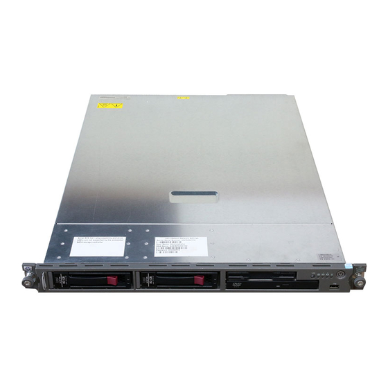
- Page 1 HP ProLiant DL320 Generation 4 Server Maintenance and Service Guide March 2006 (Second Edition) Part Number 394178-002...
- Page 2 © Copyright 2005, 2006 Hewlett-Packard Development Company, L.P. The information contained herein is subject to change without notice. The only warranties for HP products and services are set forth in the express warranty statements accompanying such products and services. Nothing herein should be construed as constituting an additional warranty. HP shall not be liable for technical or editorial errors or omissions contained herein.
-
Page 3: Table Of Contents
Contents Customer self repair ........................5 Parts only warranty service ......................... 5 Illustrated parts catalog ....................... 15 Mechanical components........................... 15 System components ..........................18 Removal and replacement procedures ................... 23 Safety considerations ..........................23 Preventing electrostatic discharge ......................23 Symbols on equipment ..........................24 Rack warnings ............................ - Page 4 SmartStart Scripting Toolkit ........................49 HP Instant Support Enterprise Edition......................49 HP ROM-Based Setup Utility ........................49 ROMPaq utility............................50 Online ROM Flash Component Utility......................50 Integrated Management Log ........................50 Integrated Lights-Out 2 technology......................51 Automatic Server Recovery ........................51 HP Systems Insight Manager ........................
-
Page 5: Customer Self Repair
HP specifies in the materials shipped with a replacement CSR part whether a defective part must be returned to HP. In cases where it is required to return the defective part to HP, you must ship the defective part back to HP within a defined period of time, normally five (5) business days. - Page 6 HP sono realizzati con numerosi componenti che possono essere riparati direttamente dal cliente (CSR, Customer Self Repair). Se in fase di diagnostica HP (o un centro di servizi o di assistenza HP) identifica il guasto come riparabile mediante un ricambio CSR, HP lo spedirà direttamente al cliente per la sostituzione.
- Page 7 La mancata restituzione del componente può comportare la fatturazione del ricambio da parte di HP. Nel caso di riparazione da parte del cliente, HP sostiene tutte le spese di spedizione e resa e sceglie il corriere/vettore da utilizzare.
- Page 8 Si no enviara el componente defectuoso requerido, HP podrá cobrarle por el de sustitución. En el caso de todas sustituciones que lleve a cabo el cliente, HP se hará cargo de todos los gastos de envío y devolución de componentes y escogerá la empresa de transporte que se utilice para dicho servicio.
- Page 9 Para este servicio de garantía exclusivo de componentes, es obligatoria la sustitución de componentes por parte del usuario (CSR). Si solicita a HP que realice la sustitución de estos componentes, tendrá que hacerse cargo de los gastos de desplazamiento y de mano de obra de dicho servicio.
- Page 10 Opcional – Peças cujo reparo feito pelo cliente é opcional. Essas peças também são projetadas para o reparo feito pelo cliente. No entanto, se desejar que a HP as substitua, pode haver ou não a cobrança de taxa adicional, dependendo do tipo de serviço de garantia destinado ao produto.
- Page 11 Customer self repair 11...
- Page 12 Customer self repair 12...
- Page 13 Customer self repair 13...
- Page 14 Customer self repair 14...
-
Page 15: Illustrated Parts Catalog
Optional—Parts for which customer self repair is optional. These parts are also designed for customer self repair. If, however, you require that HP replace them for you, there may or may not be additional charges, depending on the type of warranty service designated for your product. - Page 16 Optional: Opcional—Peças cujo reparo feito pelo cliente é opcional. Essas peças também são projetadas para o reparo feito pelo cliente. No entanto, se desejar que a HP as substitua, pode haver ou não a cobrança de taxa adicional, dependendo do tipo de serviço de garantia destinado ao produto.
- Page 17 Illustrated parts catalog 17...
-
Page 18: System Components
System components Item Description Spare part number Customer self repair (on page 5) System components Fan assembly 398442-001 Mandatory Power 450-W power supply 394982-001 Optional Boards Power button/LED board 378627-001 Mandatory System board — — a) System board 398437-001 Optional b) System board (4M processors) 415626-001 Optional... - Page 19 Item Description Spare part number Customer self repair (on page 5) f) 3.0-GHz Intel® Pentium® D 930 processor, 4- 410613-001 Optional MB L2 cache* g) 3.2-GHz Intel® Pentium® D 940 processor, 410615-001 Optional 4-MB L2 cache* h) 3.0-GHz Intel® Pentium® 4 630 processor, 2- 392168-001 Optional MB L2 cache*...
- Page 20 Optional—Parts for which customer self repair is optional. These parts are also designed for customer self repair. If, however, you require that HP replace them for you, there may or may not be additional charges, depending on the type of warranty service designated for your product.
- Page 21 Optional: Opcional—Peças cujo reparo feito pelo cliente é opcional. Essas peças também são projetadas para o reparo feito pelo cliente. No entanto, se desejar que a HP as substitua, pode haver ou não a cobrança de taxa adicional, dependendo do tipo de serviço de garantia destinado ao produto.
- Page 22 Illustrated parts catalog 22...
-
Page 23: Removal And Replacement Procedures
Removal and replacement procedures In this section Safety considerations..........................23 Preventing electrostatic discharge......................23 Symbols on equipment..........................24 Rack warnings ............................24 Server warnings and cautions........................25 Preparation procedures........................... 25 Access panel ............................27 Hard drives ............................27 Hard drive blanks........................... 29 Front bezel ............................ -
Page 24: Symbols On Equipment
• Place parts on a grounded surface before removing them from their containers. • Avoid touching pins, leads, or circuitry. • Always be properly grounded when touching a static-sensitive component or assembly. Symbols on equipment The following symbols may be placed on equipment to indicate the presence of potentially hazardous conditions. -
Page 25: Server Warnings And Cautions
("Extend the server from the rack" on page 26). If you are performing service procedures in an HP, Compaq branded, telco, or third-party rack cabinet, you can use the locking feature of the rack rails to support the server and gain access to internal components. -
Page 26: Extend The Server From The Rack
For more information about telco rack solutions, refer to the RackSolutions.com website (http://www.racksolutions.com/hp). • Power down the server (on page 26). If you must remove a server from a rack or a non-hot-plug component from a server, power down the server. -
Page 27: Remove The Server From The Rack
Remove the server from the rack To remove the server from an HP, Compaq branded, telco, or third-party rack: Power down the server (on page 26). Extend the server from the rack (on page 26). Disconnect the cabling and remove the server from the rack. For more information, refer to the documentation that ships with the rack mounting option. - Page 28 Remove the hard drive. CAUTION: To prevent improper cooling and thermal damage, do not operate the server unless all bays are populated with either a component or a blank. To replace the component, reverse the removal procedure. When adding hard drives to the server, observe the following general guidelines: •...
-
Page 29: Hard Drive Blanks
Hard drive blanks To remove the component: CAUTION: To prevent improper cooling and thermal damage, do not operate the server unless all bays are populated with either a component or a blank. To replace the component, reverse the removal procedure. Front bezel Power down the server (on page 26). -
Page 30: Sas/Sata Backplane Board
Remove the media cage (on page 33). Use the T-15 Torx screwdriver to loosen the two screws on each side of the front bezel. NOTE: The T-15 Torx screwdriver is shipped with the server and can be located on the rear panel. Slide the bezel to the left, release the USB cover by gently lifting the plastic latch, and then detach the bezel. -
Page 31: Fan Assembly
Remove the SAS/SATA backplane board. To replace the component, reverse the removal procedure. Fan assembly To remove the component: Power down the server (on page 26). Extend the server from the rack (on page 26). Remove the access panel. Remove the air baffle. Disconnect the fan cables from the system board. -
Page 32: Bbwc Battery
Remove the fan assembly. To replace the component, reverse the removal procedure. BBWC battery To remove the component: Power down the server (on page 26). Extend the server from the rack (on page 26). Remove the access panel. Remove the fan assembly ("Fan assembly"... -
Page 33: Media Cage
Media cage To remove the component: CAUTION: To prevent improper cooling and thermal damage, do not operate the server unless all bays are populated with either a component or a blank. Power down the server (on page 26). Extend the server from the rack (on page 26). Remove the access panel. -
Page 34: Diskette Drive
Remove the optical drive. To replace the component, reverse the removal procedure. Diskette drive To remove the component: CAUTION: To prevent improper cooling and thermal damage, do not operate the server unless all bays are populated with either a component or a blank. Power down the server (on page 26). -
Page 35: Power Button/Led Board
Remove the diskette drive. To replace the component, reverse the removal procedure. Power button/LED board To remove the component: Power down the server (on page 26). Extend the server from the rack (on page 26). Remove the access panel. Remove the fan assembly (on page 31). Disconnect cables from any devices installed in the media cage, if necessary ("Media cage cables"... -
Page 36: Pci Riser Board Assembly
To replace the component, reverse the removal procedure. PCI riser board assembly To remove the component: CAUTION: To prevent damage to the server or expansion boards, power down the server and remove all AC power cords before removing or installing the PCI riser board assembly. Power down the server (on page 26). -
Page 37: Storage Controller
Remove the expansion board. To replace the component, reverse the removal procedure. Storage controller To remove the component: Power down the server (on page 26). Extend the server from the rack (on page 26). Remove the access panel. Disconnect the storage controller cable. Remove the PCI riser board assembly ("PCI riser board assembly"... -
Page 38: Pci Express Riser Board
Remove the storage controller. To replace the component, reverse the removal procedure. PCI Express riser board To remove the component: Power down the server (on page 26). Extend the server from the rack (on page 26). Remove the access panel. Remove the PCI riser board assembly ("PCI riser board assembly"... -
Page 39: Dimms
You can expand server memory by installing PC4200 DDR2 unbuffered SDRAM DIMMs. The system supports up to four ECC DDR2 SDRAM DIMMs. NOTE: By default, the server is set to Advanced ECC Support. Refer to "HP ROM-Based Setup Utility (on page 49)" for more information. -
Page 40: Interleaving And Non-Interleaving Memory Configuration
The following table lists some, but not all, possible configurations. For best performance, HP recommends dual-bank interleaved mode configurations. Slot 1A Slot 2A Slot 3B Slot 4B Total memory Mode 512 MB — — — 512 MB Single-bank 512 MB —... -
Page 41: Processor
Lift the power supply from the server. To replace the component, reverse the removal procedure. Processor To remove the component: WARNING: To reduce the risk of personal injury from hot surfaces, allow the drives and the internal system components to cool before touching them. CAUTION: To prevent thermal instability and damage to the server, do not separate the processor from the heatsink. -
Page 42: System Board
Remove the heatsink. Open the processor retaining clip and bracket, and remove the processor. To replace the component, reverse the removal procedure. IMPORTANT: When replacing the heatsink, check the label on top to be sure the heatsink is properly oriented. System board To remove the component: Power down the server (on page 26). - Page 43 Disconnect the power supply cables from the system board ("Power supply" on page 40). Disconnect the SATA hard drive cables from the system board ("Cabling" on page 45). Disconnect the media cage cables from the system board ("Media cage cables" on page 47). Remove the processor ("Processor"...
-
Page 44: Battery
Battery If the server no longer automatically displays the correct date and time, you may need to replace the battery that provides power to the real-time clock. Under normal use, battery life is 5 to 10 years. WARNING: The computer contains an internal lithium manganese dioxide, a vanadium pentoxide, or an alkaline battery pack. -
Page 45: Cabling
Cabling In this section Cabling overview........................... 45 Embedded SATA controller cable routing ....................45 Optional SAS/SATA controller cable routing ..................... 46 Media cage cables..........................47 Cabling overview This section provides guidelines that help you make informed decisions about cabling the server and hardware options to optimize performance. -
Page 46: Optional Sas/Sata Controller Cable Routing
Optional SAS/SATA controller cable routing CAUTION: When routing cables, always be sure that the cables are not in a position where they can be pinched or air flow can be blocked. Slot 2 Slot 1 Cabling 46... -
Page 47: Media Cage Cables
Media cage cables Item Description Diskette drive cable Media cage power cable Optical drive cable Internal USB cable Power button/LED cable Cabling 47... -
Page 48: Diagnostic Tools
To obtain the guide, refer to any of the following sources and then select the HP ProLiant Servers Troubleshooting Guide: •... -
Page 49: Smartstart Scripting Toolkit
This automated server configuration process cuts time from each server deployed, making it possible to scale server deployments to high volumes in a rapid manner. For more information, and to download the SmartStart Scripting Toolkit, refer to the HP website (http://www.hp.com/servers/sstoolkit). -
Page 50: Rompaq Utility
• Language selection For more information on RBSU, refer to the HP ROM-Based Setup Utility User Guide on the Documentation CD or the HP website (http://www.hp.com/servers/smartstart). ROMPaq utility Flash ROM enables you to upgrade the firmware (BIOS) with system or option ROMPaq utilities. To upgrade the BIOS, insert a ROMPaq diskette into the diskette drive and boot the system. -
Page 51: Integrated Lights-Out 2 Technology
ASR increases server availability by restarting the server within a specified time after a system hang or shutdown. At the same time, the HP SIM console notifies you by sending a message to a designated pager number that ASR has restarted the system. You can disable ASR from the HP SIM console or through RBSU. -
Page 52: Usb Support
(http://www.hp.com/servers/diags). USB support HP provides both standard USB support and legacy USB support. Standard support is provided by the operating system through the appropriate USB device drivers. HP provides support for USB devices before the operating system loads through legacy USB support, which is enabled by default in the system ROM. -
Page 53: Array Diagnostic Utility
ADU is a tool that collects information about array controllers and generates a list of detected problems. ADU can be accessed from the SmartStart CD ("SmartStart software" on page 48) or downloaded from the HP website (http://www.hp.com). Diagnostic tools 53... -
Page 54: Component Identification
Component identification In this section Front panel components .......................... 54 Front panel LEDs and buttons ........................55 Rear panel components........................... 56 Rear panel LEDs and buttons ........................57 System board components........................58 System board LEDs ..........................59 System LEDs and internal health LED combinations ..................60 Internal USB connector.......................... -
Page 55: Front Panel Leds And Buttons
Front panel LEDs and buttons Item Description Status UID button/LED Blue = Identification is activated. Flashing blue = System is being remotely managed. Off = Identification is deactivated. Internal health LED Green = System health is normal. Amber = System is degraded. To identify the component in a degraded state, refer to system board LEDs (on page 59). -
Page 56: Rear Panel Components
Rear panel components Item Description PCI Express expansion slot, (optional PCI-X, full-length) PCI Express expansion slot 1, low-profile, half-length Power supply UID button/LED 10/100/1000 NIC 2 10/100/1000 NIC 1 iLO 2 management port Serial connector Keyboard connector Mouse connector Video connector USB connectors (2) Component identification 56... -
Page 57: Rear Panel Leds And Buttons
Rear panel LEDs and buttons Item Description Status iLO 2 activity Green = Activity exists. Flashing green = Activity exists. Off = No activity exists. iLO 2 link Green = Link exists. Off = No link exists. 10/100/1000 Green = Link exists. NIC 1 activity Flashing green = Activity exists. -
Page 58: System Board Components
System board components Item Description Item Description System maintenance switch Fan 2 connector NMI switch Fan 1 connector Battery Main power connector Hard drive connector 1 Processor socket Hard drive connector 2 Auxiliary power connector Front panel LED board DIMM slot 4 (bank B) connector Front USB connectors (2) DIMM slot 3 (bank B) -
Page 59: Nmi Switch
Position Default Function Off = Power-on password enabled On = Power-on password disabled * Off = Normal operation On = BIOS will clear CMOS and NVRAM * Reserved Reserved * "On" activates the function. NMI switch The NMI switch allows administrators to perform a memory dump before performing a hard reset. Crash dump analysis is an essential part of eliminating reliability problems, such as hangs or crashes in operating systems, device drivers, and applications. -
Page 60: System Leds And Internal Health Led Combinations
Combinations of illuminated system LEDs and the internal health LED indicate system status. The front panel health LEDs indicate only the current hardware status. In some situations, HP SIM may report server status differently than the health LEDs because the software tracks more system attributes. -
Page 61: Internal Usb Connector
System LED and Color Internal Health Status LED Color • Amber DIMM in slot X has reached single-bit correctable error threshold. • DIMM in slot X is in a pre-failure condition. • DIMM in slot X is an unsupported type, but valid memory exists in another bank. -
Page 62: Sata And Sas Device Numbers
SATA and SAS device numbers Item Description Device 1 Device 2 Fan assembly location Component identification 62... -
Page 63: Specifications
Specifications In this section Server specifications ..........................63 Environmental specifications ........................64 DDR2 SDRAM DIMM specifications......................64 1.44-MB diskette drive specifications......................64 SAS hard drive specifications ........................65 SATA hard drive specifications ........................ 65 Server specifications Specification Value Dimension Height 4.32 cm (1.70 in) Depth 60.96 cm (24 in) -
Page 64: Environmental Specifications
CAUTION: Be sure to install DIMMs in the proper configuration. Refer to the Documentation CD. Item Description Size* 512-MB, 1-GB, 2-GB Width 64 bits *Use only 512-MB, 1-GB, or 2-GB, 72-bit wide, 1.8-V, PC2-4200 Unbuffered ECC DDR2 DIMMs. Use HP DDR2 DIMMs only. 1.44-MB diskette drive specifications Specification Value Dimensions Height 12.7 mm (0.5 in) -
Page 65: Sas Hard Drive Specifications
Specification Value Sectors per track (high/low) 18/9 Tracks per side (high/low) 80/80 Access times Track-to-track (high/low) 3 ms/6 ms Average (high/low) 169 ms/94 ms Setting time 15 ms Latency average 100 ms Cylinders (high/low) 80/80 Read/write heads SAS hard drive specifications Item 36-GB SAS drive 72-GB SAS drive... -
Page 66: Acronyms And Abbreviations
Acronyms and abbreviations ABEND abnormal end Array Configuration Utility Array Diagnostics Utility Automatic Server Recovery BIOS Basic Input/Output System Customer Self Repair double data rate DIMM dual inline memory module error checking and correcting Integrated Lights-Out Integrated Management Log ISEE Instant Support Enterprise Edition Acronyms and abbreviations 66... - Page 67 light-emitting diode network interface controller non-maskable interrupt NVRAM non-volatile memory ORCA Option ROM Configuration for Arrays operating system peripheral component interface PCI Express peripheral component interconnect express PCI-X peripheral component interconnect extended PCIe peripheral component interconnect express POST Power-On Self Test processor power module ProLiant Support Pack random access memory...
- Page 68 RBSU ROM-Based Setup Utility read-only memory serial attached SCSI SATA serial ATA SCSI small computer system interface SDRAM synchronous dynamic RAM Systems Insight Manager SNMP Simple Network Management Protocol unit identification universal serial bus Acronyms and abbreviations 68...
-
Page 69: Index
15, 18, 54 health LEDs 55, 59 connectors 54 HP Insight Diagnostics 51 controller 45, 46 HP ProLiant Essentials Foundation Pack 51 crash dump analysis 59 HP Systems Insight Manager, overview 51 CSR (customer self repair) 5 customer self repair 5... - Page 70 management tools 48 safety considerations 23 media cage 33, 47 SATA backplane 30 memory 39, 40 scripted installation 49 memory dump 59 serial connector 58 memory, interleaving 40 serial label pull tab 29 SmartStart autorun menu 48 SmartStart Scripting Toolkit 49 SmartStart, overview 48 network connector LEDs 57 spare part numbers 15, 18...
Need help?
Do you have a question about the ProLiant DL320 Generation 4 and is the answer not in the manual?
Questions and answers