HP BladeSystem c3000 Setup And Installation Manual
Enclosure
Hide thumbs
Also See for BladeSystem c3000:
- Manual (38 pages) ,
- Quickspecs (35 pages) ,
- Specification (32 pages)
Table of Contents
Advertisement
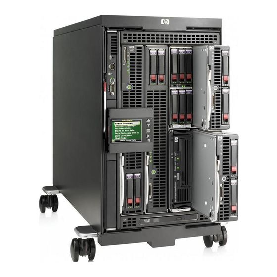
HP BladeSystem c3000 Enclosure
Setup and Installation Guide
Abstract
This document is for the person who installs, administers, and troubleshoots servers and storage systems. HP assumes you are qualified in the
servicing of computer equipment and trained in recognizing hazards in products with hazardous energy levels.
Part Number: 446987-005
February 2013
Edition: 5
Advertisement
Table of Contents

Related Manuals for HP BladeSystem c3000


Summary of Contents for HP BladeSystem c3000
-
Page 1: Hp Bladesystem C3000 Enclosure
Setup and Installation Guide Abstract This document is for the person who installs, administers, and troubleshoots servers and storage systems. HP assumes you are qualified in the servicing of computer equipment and trained in recognizing hazards in products with hazardous energy levels. - Page 2 © Copyright 2007, 2013 Hewlett-Packard Development Company, L.P. The information contained herein is subject to change without notice. The only warranties for HP products and services are set forth in the express warranty statements accompanying such products and services. Nothing herein should be construed as constituting an additional warranty. HP shall...
-
Page 3: Table Of Contents
Enclosure front components ........................12 Device bay numbering ........................12 HP BladeSystem Insight Display components ..................14 HP BladeSystem Onboard Administrator connectors and LEDs ............. 14 Enclosure rear components ........................15 Fan bay numbering ........................16 Fan LEDs ............................16 Power supply bay numbering ...................... - Page 4 Cabling the network to the enclosure ....................55 Installing a PDU ............................56 Powering up the enclosure ........................56 Using the HP BladeSystem Insight Display ..................57 Insight Display overview ........................... 57 Installing and configuring the Insight Display....................57 Accessing the HP BladeSystem Insight Display ..................... 63 Navigating the Insight Display ........................
-
Page 5: Planning The Installation
A half-height server or storage blade Full-height device (quantity as ordered) A full-height server or storage blade HP c-Class blade SUV cable (local I/O A cable with serial, USB, and video connectors cable) that attaches to the I/O connector on the front of... -
Page 6: Platinum Features
A checklist that guides you through installation of the enclosure and its components * Not shown Platinum features The HP BladeSystem c3000 Platinum Enclosure has the following features that are not available on previous generations of c3000 enclosures: • Intelligent infrastructure that includes:... -
Page 7: Rack-Free Environment Requirements
Rack-free environment requirements The HP BladeSystem c3000 Enclosure (referred to as the enclosure) can be used in a rack-free environment. The following conditions must be met when performing a rack-free installation: •... - Page 8 WARNING: To reduce the risk of personal injury or equipment damage when unloading a rack: At least two people are needed to safely unload the rack from the pallet. An empty 42U rack • can weigh as much as 115 kg (253 lb), can stand more than 2.1 m (7 ft) tall, and might become unstable when being moved on its casters.
-
Page 9: Temperature Requirements
IMPORTANT: Data on the dimensions and weights of HP BladeSystem c-Class components can be found in the HP BladeSystem c-Class Maintenance and Service Guide. The same data can be determined by using the online HP BladeSystem c-Class Sizing Utility. Temperature requirements To ensure continued safe and reliable equipment operation, install or position the rack in a well ventilated, climate-controlled environment. -
Page 10: Power Requirements
Leave a minimum clearance of 121.9 cm (48 in) from the back of the rack to the rear of another rack or row of racks. HP BladeSystem servers draw cool air in through the front and expel warm air through the rear of the enclosure. Therefore, the front of the rack enclosure must be adequately ventilated to enable ambient room air to enter the enclosure, and the rear of the enclosure must be adequately ventilated to enable the warm air to escape from the enclosure. - Page 11 Because of the high ground-leakage currents associated with this equipment, HP recommends the use of a PDU that is either permanently wired to the building’s branch circuit or includes a nondetachable cord that is wired to an industrial-style plug.
-
Page 12: Identifying Components And Leds
Identifying components and LEDs Enclosure front components Item Description Device bays ("Device bay numbering" on page 12) CD/DVD-ROM drive Onboard Administrator tray containing Onboard Administrator 2 Insight Display Onboard Administrator tray containing Onboard Administrator 1 or an Onboard Administrator blank Device bay numbering Each enclosure requires interconnects to provide network access for data transfer. - Page 13 Full-height device bay numbering Half-height device bay numbering Identifying components and LEDs 13...
-
Page 14: Hp Bladesystem Insight Display Components
Accepts the highlighted selection and navigates to the selected menu Down arrow button Moves the menu selection down one position Up arrow button Moves the menu selection up one position HP BladeSystem Onboard Administrator connectors and LEDs Identifying components and LEDs 14... -
Page 15: Enclosure Rear Components
Item Description Status Serial connector Serial RS232 DB-9 connector with PC standard pinout UID LED Blue = UID on Dark = UID off Active Onboard An LED that indicates which Onboard Administrator LED Administrator is active Health LED Green = OK Red = Critical error A USB 2.0 Type A connector that connects supported USB devices... -
Page 16: Fan Bay Numbering
Fan bay numbering Fan LEDs LED color Fan status The fan is working. Solid green The fan has failed. Solid amber See the Insight Display screen. Flashing amber Identifying components and LEDs 16... -
Page 17: Power Supply Bay Numbering
Power supply bay numbering Power supply LED Power LED Status No AC power to power supply units AC is present. Standby output is on, output is disabled. Green AC is present. Standby output is on, power supply DC output is on and Green Power supply failure (includes overvoltage and overtemperature) Identifying components and LEDs 17... -
Page 18: Interconnect Bay Numbering
Interconnect bay numbering To support network connections for specific signals, install the interconnect module in the appropriate bay. Server blade signal Interconnect bay Interconnect bay Notes number label — NICs 1, 2, 3, and 4 (embedded) Four port cards connect to bay 2 Mezzanine 1 Mezzanine 2 •... -
Page 19: Installing Components
Installing components Installation overview To setup and install the enclosure: Disassemble the enclosure. For a rack-free installation (on page 22), set up the enclosure on an appropriate surface, then reassemble the enclosure. For a rack installation, install the enclosure in the rack ("Installing the enclosure in a rack"... - Page 20 With the enclosure still on the pallet, remove all components from the front and rear of the enclosure. Remove the front cage: Loosen the four thumbscrews inside the front cage assembly and open the hinges completely. Installing components 20...
- Page 21 Use the handles on the top of the enclosure to extend the front cage until it hits the safety stops. Grasp the handholds on the sides of the enclosure. The release levers are located inside the handholds. Disengage the release levers on both sides of the front cage. WARNING: When removing and lifting the front cage, always grasp the handholds as far forward as possible.
-
Page 22: Rack-Free Installation
Use the handholds to extend and remove the front cage from the enclosure. Rack-free installation To set up the enclosure in a rack-free environment: Select the location for the enclosure. For more information, see "Rack-free environment requirements (on page 7)." WARNING: To reduce the risk of personal injury or damage to the equipment in a rack-free environment:... -
Page 23: Measuring With The Rack Template
Install the enclosure into the rack ("Installing the enclosure in a rack" on page 24). Measuring with the rack template The rack template ships with the rack rail kit and provides detailed instructions on where to position the enclosure rack rails and where to install the four cage or clip nuts. Each enclosure kit includes the rack rails recommended for that enclosure. -
Page 24: Installing The Enclosure In A Rack
Slide the front end of the rail to the rack front column. When fully seated, the rack rail will lock into place. Repeat the procedure for the right rack rail. Installing the enclosure in a rack WARNING: Always use at least two people to lift an enclosure into the rack. If the enclosure is being loaded into the rack above chest level, a third person must assist with aligning the enclosure with the rails while the other two people support the weight of the enclosure. -
Page 25: Installing The Front Cage Into The Enclosure
Tighten the thumbscrews to secure the enclosure to the rack. Repeat the procedure for the remaining enclosures. NOTE: You can install up to seven 6U enclosures in a 42U rack. If you are installing more than one enclosure, install the first enclosure in the bottom of the rack, and then install additional enclosures by moving up the rack to the next available opening. -
Page 26: Component Installation
Component installation The following sections contain installation instructions for the individual enclosure components. All components must be installed and cabled before you power up the enclosure. There is no specific installation order requirement for the enclosure components. Installing a power supply Slide the power supply into the power supply bay until the device locks into place. -
Page 27: Installing A Full-Height Blade
Install power supply blanks in any unused power supply bay. Populating power supply bays For AC redundant (N+N power supplies) configurations, an even number of power supplies is required. For this configuration, where N is the number of power supplies being used, populate the power supply bays as shown. - Page 28 Remove the connector covers. Prepare the blade for installation. Installing components 28...
- Page 29 Install the blade in the empty bay. NOTE: If you plan to install four HP Active Cool Fans, you can install up to two full-height blades. Populate device bay 1 first, then populate device bay 2. If you plan to install six HP Active Cool Fans, blades can be installed in any configuration.
- Page 30 Slide the divider locking tab down: Installing components 30...
- Page 31 For the half-height divider, push the divider toward the back of the enclosure until the divider stops. Slide the divider to the left to disengage the tabs from the divider wall, and then rotate the divider clockwise. For the mini divider, push the divider toward the back of the enclosure until the divider drops out of the chassis.
- Page 32 Remove the device bay divider from the enclosure. Creating a full-height device bay blank Obtain the coupler plate: If you are using a device bay blank that came with the enclosure, the coupler plate can be found with the contents of the full-height device shipping box. If you are using a device bay blank that you purchased as an option, remove the coupler plate from inside the blank.
-
Page 33: Installing A Half-Height Blade
Fit the slots on the bottom of the second blank on to the tabs on the coupler plate, and then slide the second blank forward until it snaps in place. Install the full-height blank into the device bay. Installing a half-height blade Remove the blank. - Page 34 Install the blade in the empty bay. NOTE: If you plan to install four HP Active Cool 100 Fans, you can install up to four half-height blades. Populate the device bays in the following order: 1, 2, 5, 6. If you plan to install six HP Active Cool 100 Fans, blades can be installed in any configuration.
- Page 35 Remove the full-height blade, storage blade, or device bay blank. Install the divider or proceed to step 3 to install the half-height divider. Align the three tabs on the top edge of the divider with the openings in the enclosure, and then slide the divider straight back.
- Page 36 Slide up the divider locking tab to lock it. Install the half-height divider. Slide the divider locking tab down: Align the three tabs on the bottom edge of the divider with the openings in the enclosure, and rotate the divider counter-clockwise. CAUTION: Be sure that all five tabs (three on the bottom edge of the divider and two on the top edge of the divider) are fully inserted before sliding the divider forward to complete the...
-
Page 37: Installing Fans
For more information, see "Fan bay numbering (on page 16)." NOTE: You cannot install HP Active Cool 100 fans and HP Active Cool 200 fans in the same enclosure. The Onboard Administrator sends an error message, and you must remove the type of fan with the least number of units installed. - Page 38 Turn the handle counterclockwise to the unlock position, and pull the fan or fan blank from the enclosure. Slide the fan into the enclosure until it locks in place. NOTE: When installing a fan in the top row of fan bays, orient the fan so that the LED is in the lower right corner.
-
Page 39: Installing A Kvm Module
Installing a KVM module You can use the optional HP BladeSystem c3000 KVM Module to connect the enclosure to a USB keyboard, video monitor, and USB mouse (KVM). You can also connect the KVM module to the HP Server Console Switch or HP IP Console Switch using the HP USB Interface Adapter. - Page 40 Connect a USB keyboard and mouse to the USB connectors on the c3000 KVM module. The USB connectors are interchangeable. To connect the c3000 KVM module to an HP Server Console Switch or an HP IP Console Switch: Connect the optional USB interface adapter to the video connector and to one of the USB connectors on the c3000 KVM module.
- Page 41 Connect the CAT5 end of the KVM interface adapter to an optional HP Console Switch. Removing the HP BladeSystem c3000 KVM module Disconnect all cables from the c3000 KVM module. Press the tab, and then pull the c3000 KVM module from the enclosure.
-
Page 42: Installing Interconnect Modules
Install a blank in an unused KVM module bay. When fully inserted, the device locks into place. Installing interconnect modules There are four single-wide interconnect bays in the enclosure. Interconnect bay 1 is reserved for a gigabit Ethernet switch or pass-through. Installation into the remaining interconnect bays depends on the type and location of the mezzanine card installed in the server blade. -
Page 43: Mapping To Interconnect Ports
Install the interconnect module in the enclosure. Mapping to interconnect ports Several port types are referenced in the following tables. • Examples of 1x ports are 1-Gb Ethernet (1 GbE) switch modules and Fibre Channel interconnect modules. • An example of a 2x port is a Serial Attached SCSI (SAS) interconnect module. (Reserved for future use.) •... - Page 44 Mapping half-height blades The following table lists the available configurations for half-height devices installed in device bay N (1–8) Connection Port number Connects to Comments interconnect bay/port NIC 1 1/Port N One single-wide Ethernet Embedded NIC NIC 2 1/Port N+8 interconnect module 1x/2x port 1 2/Port N...
- Page 45 Connection Port number Connects to Comments interconnect bay/port 1x/2x port 1 3/Port N One or two single-wide Mezzanine slot 2—1x or 1x/2x port 2 4 Port N interconnect modules 2x cards 1x/2x port 3 3/Port N+8 1x/2x port 4 4/Port N+8 4x port 1 3/Port N One double-wide...
- Page 46 Connection Port number Connect to interconnect Comments bay/port NIC 1 1/Port N+4 One single-wide Ethernet Embedded NIC NIC 2 1/Port N+12 interconnect module NIC 3 1/Port N NIC 4 1/Port N+8 1x/2x port 1 2/Port N One single-wide interconnect Mezzanine slot 1—1x or 1x/2x port 2 2/Port N+8 module...
-
Page 47: Mapping Bl2X220C Blades
Mapping BL2x220c blades To support network connections for specific signals, install an interconnect module in the bay corresponding to the embedded NIC or mezzanine signals. Connection Port number Connects to interconnect Comments bay/port Server A: NIC 1 1/Port N Two single-wide Ethernet Embedded NIC Server A: NIC 2 2/Port N... - Page 48 Connection Port number Connects to interconnect Comments bay/port Server A: Mezz port 1 3/Port N Mezzanine slot 1—1x, • Two single-wide modules Server A: Mezz port 2 4/Port N 2x, or 4x cards or one double-wide Server B: Mezz port 1 3/Port N+8 interconnect module Server B: Mezz port 2...
-
Page 49: Removing Interconnect Bay Dividers
Interconnect bay crosslinks Interconnect bay crosslinks are wired between adjacent interconnect bay pairs. You can enable these signals to provide module-to-module connections. Onboard Administrator disables the interconnect bay crosslinks in instances where the crosslinks cannot be used, such as when two different modules reside in adjacent horizontal interconnect bays. -
Page 50: Installing The Enclosure/Onboard Administrator Link Module
To reinstall an interconnect bay divider, align the interconnect bay divider with the rail, and slide the divider into the enclosure until it locks into place. Installing the enclosure/Onboard Administrator link module Slide the enclosure/Onboard Administrator link module into the bay until the device locks into place. Connecting locally to a server blade with video and USB devices Use the local I/O cable to connect a monitor and any of the following USB devices: •... -
Page 51: Accessing A Server Blade With Local Kvm
Connect a USB keyboard to the second USB connector. Item Description Monitor USB mouse HP c-Class Blade SUV cable Server blade Video connector USB keyboard Accessing local media devices Use the following configuration when configuring a blade or loading software updates and patches from a USB CD/DVD-ROM or a USB diskette. - Page 52 The Onboard Administrator with version 2.0 or greater firmware supports attaching a CD or DVD to any or all iLOs using the optional enclosure DVD drive or an external HP DVD drive for operating system installation or software updates. See "Enclosure Settings screen (on page 66)"...
-
Page 53: Cabling And Powering Up The Enclosure
Cabling and powering up the enclosure Cabling the enclosure After all system hardware is installed, cable the components. See the HP ProLiant BladeSystem c-Class Site Planning Guide on the Documentation CD or the HP website (http://www.hp.com) for additional cabling and site planning requirements. -
Page 54: Enclosure Link Cabling
If more c-Class enclosures are added to the rack at a later time, the open enclosure link-up port on the top enclosure can be used to link the new enclosure. NOTE: The HP BladeSystem c-Class enclosure link ports are not compatible with the HP BladeSystem p-Class enclosure link ports. Cabling and powering up the enclosure 54... -
Page 55: Cabling A Pc To The Enclosure Service Port
Open a web browser on the PC and enter the active Onboard Administrator module Service IP address found in the Enclosure Info screen in step 2. Log into the Onboard Administrator. For more information on using Onboard Administrator, see the HP BladeSystem Onboard Administrator User Guide. -
Page 56: Installing A Pdu
Installing a PDU The PDU can be installed in either a 1U or a 0U configuration. See the installation instructions that came with the PDU for specific details on installing the PDU into the rack. NOTE: Total VA load of the attached enclosures should not exceed the VA capacity of the PDU. Do not exceed the rated current on circuit breakers. -
Page 57: Using The Hp Bladesystem Insight Display
Insight Display overview The Insight Display enables the rack technician to configure the enclosure initially. It also provides information about the health and operation of the enclosure. See the HP BladeSystem Onboard Administrator User Guide for additional information. The Insight Display background color varies with the condition of the enclosure health: •... - Page 58 Power Mode—The default setting is AC Redundant. The following selections are valid: AC Redundant Power Supply Redundant None Power Limit—The default setting is Not Set. You can change the limit by increments of 50 Watts. Using the HP BladeSystem Insight Display 58...
- Page 59 DVD Drive—The default setting is Disconnected on all blades. The DVD Connect Status menu displays the current DVD connection status with an icon. Select a DVD icon on the DVD Connect menu to navigate to the Blade DVD Connection menu. Using the HP BladeSystem Insight Display 59...
- Page 60 Disconnect DVD Hardware—Disconnects the current media connection and returns to the DVD Connect Status menu. The following selections are valid: No Power Change—Connects the selected media to the server only. Using the HP BladeSystem Insight Display 60...
- Page 61 You can return to the Enclosure Settings menu after the Installation Wizard completes to change the Onboard Administrator module IP addresses, if necessary. Move the cursor to Accept, and press the OK button. Using the HP BladeSystem Insight Display 61...
- Page 62 All configuration errors prevent the operation of the enclosure and should be corrected immediately. Open a browser and connect to the active Onboard Administrator module using the Onboard Administrator IP address that was configured during the Insight Display installation wizard process. Using the HP BladeSystem Insight Display 62...
-
Page 63: Accessing The Hp Bladesystem Insight Display
To access the Insight Display, push on the exposed end. IMPORTANT: The length of HP ProLiant Gen8 server blades is longer than previous generations, and these server blades protrude slightly from the edge of the enclosure. The initial stopping point of the Insight Display allows for the screen to be flush with previous generation servers. -
Page 64: Navigating The Insight Display
Blade or Port Info ("Blade or Port Info screen" on page 68) • Turn Enclosure UID on/off ("Turn Enclosure UID On/Off screen" on page 69) • View User Note ("View User Note screen" on page 70) Using the HP BladeSystem Insight Display 64... -
Page 65: Health Summary Screen
The only option active on the navigation bar is Back to Main Menu. Select Back to Main Menu, and press the OK button to return to the main menu. Using the HP BladeSystem Insight Display 65... -
Page 66: Enclosure Settings Screen
DVD drive to any or all blades in the enclosure. This feature can be used to install an operating system or software on the blade(s). If the optional DVD drive is not present, an external HP USB DVD drive can be used with this feature instead. TIP: Set a PIN to protect the enclosure settings from changes. -
Page 67: Enclosure Info Screen
Active OA IP address • Active OA Service IP address • Current health status of the enclosure • Current enclosure ambient temperature • Current AC input power to the enclosure • Enclosure name • Rack name Using the HP BladeSystem Insight Display 67... -
Page 68: Blade Or Port Info Screen
OK button. Select Blade Info or Port Info, and press the OK button. To view information about the blade, select Blade Info and press the OK button. To view the ports used by a specific blade, select Port Info and press the OK button. Using the HP BladeSystem Insight Display 68... -
Page 69: Turn Enclosure Uid On/Off Screen
"Turn Enclosure UID on" when the enclosure UID is off. Selecting Turn Enclosure UID On from the main menu turns on the rear enclosure UID LED and changes the color of the Insight Display screen to blue. Using the HP BladeSystem Insight Display 69... -
Page 70: View User Note Screen
Insight Display. The technician uses the Insight Display buttons to select from a set of prepared responses, or dials in a custom response message on the ? line. To send a response back to the Administrator, navigate the cursor to Send, then press the OK button. Using the HP BladeSystem Insight Display 70... -
Page 71: Usb Menu Screen
Onboard Administrator module on the front of the enclosure or a USB port on the optional KVM module. To access the USB Menu: Insert a USB key into Onboard Administrator. From the Main Menu, select USB Menu. Using the HP BladeSystem Insight Display 71... -
Page 72: Kvm Menu Screen
Select this button to deactivate the Insight Display and activate the VGA connector on the KVM module.Only one of the two interfaces can be active at a time. Access the KVM Menu by choosing one of the following options: Using the HP BladeSystem Insight Display 72... - Page 73 From a USB keyboard connected to the KVM module, press PrtSc or SysReq on the USB keyboard. If the KVM module is connected to an HP rack KVM switch using a VGA or USB adapter, press PrtSc to activate the HP rack KVM selection menu.
- Page 74 Server DVD—Select this DVD icon for a server to change the enclosure DVD connection for this server. • Server Health—Select this Health icon to display the current health state for that server. • Insight Display—Select the Insight Display button to access Insight Display screens from the KVM Menu. Using the HP BladeSystem Insight Display 74...
- Page 75 KVM keyboard. This launches a full screen text console to the active OA CLI. Press PrtSc to exit the OA CLI console and return to the KVM Menu. • Help—Select Help to view the KVM help information. Using the HP BladeSystem Insight Display 75...
-
Page 76: Troubleshooting
The HP BladeSystem c-Class Enclosure Troubleshooting Guide provides procedures and solutions for troubleshooting HP BladeSystem c-Class enclosures. This guide explains how to use the Insight Display to troubleshoot enclosures, and it includes a flowchart to help you navigate the troubleshooting process. To view the guide, see the HP website (http://www.hp.com/support/BladeSystem_Enclosure_TSG_en). -
Page 77: Warnings And Cautions
Warnings and cautions WARNING: Only authorized technicians trained by HP should attempt to repair this equipment. All troubleshooting and repair procedures are detailed to allow only subassembly/module-level repair. Because of the complexity of the individual boards and subassemblies, no one should attempt to make repairs at the component level or to make modifications to any printed wiring board. -
Page 78: Insight Display Errors
To clear errors that occur after initial powerup and configuration, see the HP BladeSystem Onboard Administrator User Guide for information. The following types of errors can occur when installing and configuring the enclosure: •... -
Page 79: Location Errors
Location errors Location (installation) errors occur when the component is not installed in the appropriate bay. Location errors can occur on blades, storage blades, power supplies, and fans. To correct a location error: Use the arrow buttons to navigate to Fix This, and press OK. Review and complete the corrective action suggested by the Insight Display. -
Page 80: Support And Other Resources
Active Health System log (HP ProLiant Gen8 or later products) Download and have available an Active Health System log for 3 days before the failure was detected. For more information, see the HP iLO 4 User Guide or HP Intelligent Provisioning User Guide on the HP website (http://www.hp.com/go/ilo/docs). - Page 81 HP specifies in the materials shipped with a replacement CSR part whether a defective part must be returned to HP. In cases where it is required to return the defective part to HP, you must ship the defective part back to HP within a defined period of time, normally five (5) business days. The defective part must be returned with the associated documentation in the provided shipping material.
- Page 82 HP sono realizzati con numerosi componenti che possono essere riparati direttamente dal cliente (CSR, Customer Self Repair). Se in fase di diagnostica HP (o un centro di servizi o di assistenza HP) identifica il guasto come riparabile mediante un ricambio CSR, HP lo spedirà direttamente al cliente per la sostituzione.
- Page 83 Si, durante la fase de diagnóstico, HP (o los proveedores o socios de servicio de HP) identifica que una reparación puede llevarse a cabo mediante el uso de un componente CSR, HP le enviará dicho componente directamente para que realice su sustitución. Los componentes CSR se clasifican en dos categorías:...
- Page 84 HP se hará cargo de todos los gastos de envío y devolución de componentes y escogerá la empresa de transporte que se utilice para dicho servicio. Para obtener más información acerca del programa de Reparaciones del propio cliente de HP, póngase en contacto con su proveedor de servicios local.
- Page 85 Opcional – Peças cujo reparo feito pelo cliente é opcional. Essas peças também são projetadas para o reparo feito pelo cliente. No entanto, se desejar que a HP as substitua, pode haver ou não a cobrança de taxa adicional, dependendo do tipo de serviço de garantia destinado ao produto.
- Page 86 Support and other resources 86...
- Page 87 Support and other resources 87...
-
Page 88: Regulatory Information
Regulatory information Safety and regulatory compliance For safety, environmental, and regulatory information, see Safety and Compliance Information for Server, Storage, Power, Networking, and Rack Products, available at the HP website (http://www.hp.com/support/Safety-Compliance-EnterpriseProducts). Turkey RoHS material content declaration Ukraine RoHS material content declaration Warranty information HP ProLiant and X86 Servers and Options (http://www.hp.com/support/ProLiantServers-Warranties) -
Page 89: Electrostatic Discharge
Electrostatic discharge Preventing electrostatic discharge To prevent damaging the system, be aware of the precautions you need to follow when setting up the system or handling parts. A discharge of static electricity from a finger or other conductor may damage system boards or other static-sensitive devices. -
Page 90: Acronyms And Abbreviations
Acronyms and abbreviations Canadian Standards Association Customer Self Repair electrostatic discharge International Electrotechnical Commission Integrated Lights-Out power distribution unit RETMA Radio Electronics Television Manufacturers Association (rack spacing) TMRA recommended ambient operating temperature unit identification uninterruptible power system universal serial bus Acronyms and abbreviations 90... -
Page 91: Documentation Feedback
Documentation feedback HP is committed to providing documentation that meets your needs. To help us improve the documentation, send any errors, suggestions, or comments to Documentation Feedback (mailto:docsfeedback@hp.com). Include the document title and part number, version number, or the URL when submitting your feedback. -
Page 92: Index
88 configuration errors 79 firmware, updating 71 configuring Onboard Administrator 71 front cage, installing 25 configuring the enclosure with HP BladeSystem Insight front cage, removing 19 Display 57 front components 12, 14 cooling errors 78 full-height device bay blank, creating 32... - Page 93 Health Summary screen 64, 65 HP BladeSystem Insight Display components 14 HP BladeSystem Insight Display errors 78, 79 LED identification 12 HP BladeSystem Insight Display screen 14, 57, 64 LEDs 16, 17, 64, 69 HP BladeSystem Insight Display, accessing 63 LEDs, fan 16...
- Page 94 phone numbers 80 static electricity 89 populating power supply bays 27 support 80 port types 43 supported servers 76 power configurations 26 symbols on equipment 76 power cord 77 power distribution unit (PDU) 10, 56 power errors 78 Taiwan battery recycling notice 88 power requirements 10, 26 technical support 80 power supplies 26...
Need help?
Do you have a question about the BladeSystem c3000 and is the answer not in the manual?
Questions and answers